Forth processor on VHDL
In this article I will tell how to write the processor on VHDL. There won't be a lot of code (at least I hope so). The full code is laid out on the githaba, and in the same place, you can see several iterations of writing.
The processor falls under the class of soft-processors .
First of all, you need to choose a processor architecture. I will use the RISC architecture for the processor and the Harvard memory organization architecture .
The processor will be without a two-state pipeline:
Since we write the forth-processor, it will be a stack. This will reduce the bit team, because it will not need to store indexes of registers with which calculations are performed. For operations, the processor will have two upper stacks available.
The data stack and the return stack will be separate.
')
In FPGA there is a block memory with a configuration of 18 bits * 1024 cells. Focusing on it, I choose the bit width of a 9-bit command (2048 commands fit in one block of memory).
Let the data memory capacity be “standard” at 32 bits.
I “communicate” with peripheral devices using a bus.
The scheme of all this disgrace will be approximately the following.

With the architecture decided, now "let's try with all this take off." Now you need to come up with a system of commands.
All processor commands can be divided into several groups:
So, we have 9 discharges of the team, in which we need to meet.
The size of the command is less than the digit capacity of the data, so you need to come up with a mechanism for loading numbers.
I chose the following command format to load literals onto the stack:
Elder, 8 bits of the command will be a sign of loading numbers. The remaining 8 bits are the actual number loaded onto the stack.
But the data width is 32 bits, and only 8 bits can be loaded so far.
We agree that if there are several LIT commands in a row, then this is considered to be loading one number. The first command loads a number on the stack (by expanding it), each subsequent modifies the top number on the stack, shifting it 8 bits to the left and entering the value from the command in the lower part. Thus, it is possible to load a number of any bit depth with a sequence of several LIT commands.
To separate multiple numbers, you can use any command (for example, NOP).
I decided to break all other commands into groups for easy decoding. We will group by how they affect the stack.
Team groups:
Transitions:
JMP and CALL commands take the address from the stack and go through it (call additionally puts the return address on the appropriate stack).
The IF command takes the transition address (the top number on the stack) and the transition flag (the next number). If the sign is equal to zero, then go to the address.
The RET command works with the return stack, picking up the top number and navigating through it.
If the command is not a transition, then the command counter is incremented by one.
For the description of commands the stack notation is used , which looks like this:
<State of the stack before the execution of the word> - <State of the stack after the execution
words>
The top of the stack is on the right, i.e. 2 3 - 5 means that before the word is executed
at the top of the stack was the number 3, and below it the number 2; after doing these numbers
turned out to be removed, and on top instead of them was the number 5.
Example:
DUP (a - aa)
DROP (ab - a)
Take the minimum set of commands with which you can at least do something.
On the stack for one processor clock cycle, you can write 1 number; in the fort there is a SWAP command that swaps the top 2 numbers on the stack. To implement it you need 2 teams. The first command is NIP (ab - b), deletes the second number “a” from above and stores it in a temporary register, and the second command TEMP> (- a) extracts this number from the temporary register and puts it on top of the stack.
Realization of memory.
Memory code and data is implemented through a template:
Ram is a signal declared as follows:
Memory can be initialized as follows:
Stacks are implemented through a similar pattern.
The only difference from the memory template is that it “forwards” the recorded value to the output. With the previous template, the recorded value would have been received at the next, after recording, tact.
The synthesizer automatically recognizes these patterns and generates the appropriate memory blocks. This is evident in the report. For example, for a data stack, it looks like this:
I think it makes no sense to give the full code for the implementation of memory, it is, in fact, a template.
The main cycle of the processor - on the first clock, the command is sampled, on the second - execution. To determine which processor is on, a fetching signal is made.
The easiest option to decode and execute a command is a large “case” for all options. For ease of writing, it is better to divide it into several components.
In this project, I broke it into 3 parts:
Sampling is part of the command, the lower 4 bits are not used.
All declared groups of teams are painted. You will only need to change this case when a new group of teams appears.
The next case will be responsible for the execution of the command. It generates data for the data stack (sorry for the tautology), the signal iowr for the OUTPORT command, etc.
So far only 2 teams have been implemented. Loading numbers on the stack and adding the top two numbers on the stack. This is enough for “testing the idea”, and if these 2 teams work, most of the rest will be implemented “on a template” without any problems.
And the last case - the formation of the following address for the command counter:
Implemented basic transition commands. The jump address is taken from the stack.
Before moving on, it is advisable to test already written code. I created TestBench, in which I entered only the output of the reset signal to the processor in the first 100 ns.
The code memory is initialized as follows:
First, several numbers are put, the addition operation is tested and the stack is cleared with the DROP command. Next, the transition, subroutine call, and return are tested.
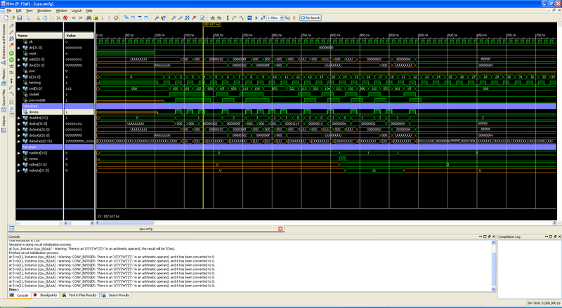
The result of the simulation is shown in the following pictures (clickable):
The whole test:
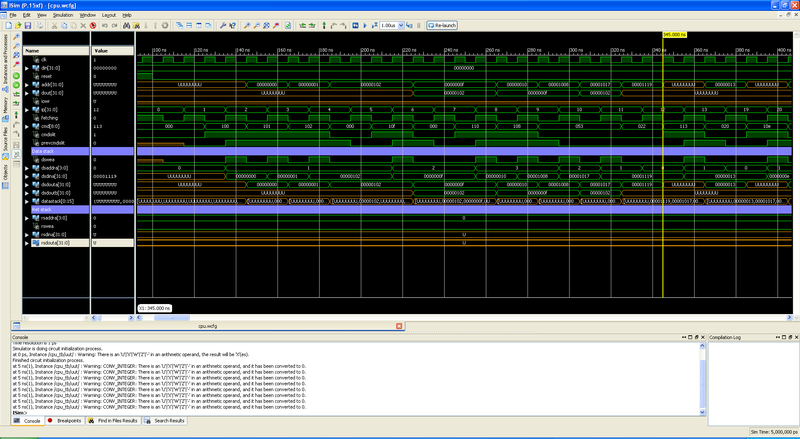
Test load numbers:
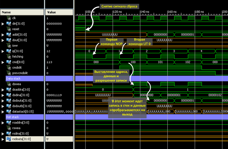
The figure shows the execution of the Lit 0 command. After removing the reset signal, the command counter is zero (ip = 0) and the processor is told that it is in the command fetch phase (fetching = '1'). At the first tact sampling is done. The first NOP command does nothing but increase the command counter (however, any unknown command will increase the command counter, and also can do something with the data stack, depending on the group in which it is located).
Team # 1 is loading number 0 onto the stack. At the execution step, 3 signals are set: the address of the data stack is incremented by 1, the data is set, and the write enable signal is set.
At the next clock cycle of the sample, the value “0” is written to the stack at the address “1”. The value, also, is immediately "forwarded" to the output (so that the next command operates with a new value). The write enable signal is removed.
Team # 2 is also a command for loading numbers onto the stack. Because it follows the LIT command, then the new number per stack will not be loaded, but the upper one will be modified. It is shifted 8 bits to the left, the lower part is written to the value from the command (which is 0x01).
The command # 3 performs the same operations as the command # 2. The number on the stack, after its operation, is 0x0102.
The first teams are tested. Almost all the remaining commands are written in a pattern (“draw circles, draw the rest of the owl”).
The purpose of the article was to show that you can write the processor yourself, and, I hope, I did it at least to some extent. The next step is to write the bootloader and cross-compiler, if the habrasoobschestvu would be interested in this article.
Github Project: github.com/whiteTigr/vhdl_cpu
Processor Code: github.com/whiteTigr/vhdl_cpu/blob/master/cpu.vhd
Testbench code (although there is almost nothing in it): github.com/whiteTigr/vhdl_cpu/blob/master/cpu_tb.vhd
The processor falls under the class of soft-processors .
Architecture
First of all, you need to choose a processor architecture. I will use the RISC architecture for the processor and the Harvard memory organization architecture .
The processor will be without a two-state pipeline:
- Sampling commands and operands
- Execution of the command and saving the result
Since we write the forth-processor, it will be a stack. This will reduce the bit team, because it will not need to store indexes of registers with which calculations are performed. For operations, the processor will have two upper stacks available.
The data stack and the return stack will be separate.
')
In FPGA there is a block memory with a configuration of 18 bits * 1024 cells. Focusing on it, I choose the bit width of a 9-bit command (2048 commands fit in one block of memory).
Let the data memory capacity be “standard” at 32 bits.
I “communicate” with peripheral devices using a bus.
The scheme of all this disgrace will be approximately the following.
Command system
With the architecture decided, now "let's try with all this take off." Now you need to come up with a system of commands.
All processor commands can be divided into several groups:
- Load literal (numbers) onto stack
- Transitions (conditional transition, subroutine call, return)
- Accessing data memory (read and write)
- Access to the bus (the meaning is the same as accessing the memory).
- Teams ALU.
- Other teams.
So, we have 9 discharges of the team, in which we need to meet.
Loading literals
The size of the command is less than the digit capacity of the data, so you need to come up with a mechanism for loading numbers.
I chose the following command format to load literals onto the stack:
| Mnemonics | eight | 7 | 6 | five | four | 3 | 2 | one | 0 |
|---|---|---|---|---|---|---|---|---|---|
| Lit | one | Lit | |||||||
Elder, 8 bits of the command will be a sign of loading numbers. The remaining 8 bits are the actual number loaded onto the stack.
But the data width is 32 bits, and only 8 bits can be loaded so far.
We agree that if there are several LIT commands in a row, then this is considered to be loading one number. The first command loads a number on the stack (by expanding it), each subsequent modifies the top number on the stack, shifting it 8 bits to the left and entering the value from the command in the lower part. Thus, it is possible to load a number of any bit depth with a sequence of several LIT commands.
To separate multiple numbers, you can use any command (for example, NOP).
Command grouping
I decided to break all other commands into groups for easy decoding. We will group by how they affect the stack.
| Mnemonics | eight | 7 | 6 | five | four | 3 | 2 | one | 0 |
|---|---|---|---|---|---|---|---|---|---|
| Lit | 0 | Group | Team | ||||||
Team groups:
| Group | Takes from the stack | Puts on the stack | Example |
|---|---|---|---|
| 0 | 0 | 0 | NOP |
| one | 0 | one | DEPTH |
| 2 | one | 0 | Drop |
| 3 | one | one | DUP @ |
| four | 2 | 0 | ! OUTPORT |
| five | 2 | one | Arithmetic (+, -, AND) |
Transitions:
| Mnemonics | eight | 7 | 6 | five | four | 3 | 2 | one | 0 |
|---|---|---|---|---|---|---|---|---|---|
| Jmp | 0 | 2 | 0 | ||||||
| CALL | 0 | 2 | one | ||||||
| IF | 0 | four | 0 | ||||||
| RET | 0 | 0 | one | ||||||
JMP and CALL commands take the address from the stack and go through it (call additionally puts the return address on the appropriate stack).
The IF command takes the transition address (the top number on the stack) and the transition flag (the next number). If the sign is equal to zero, then go to the address.
The RET command works with the return stack, picking up the top number and navigating through it.
If the command is not a transition, then the command counter is incremented by one.
Command table
For the description of commands the stack notation is used , which looks like this:
<State of the stack before the execution of the word> - <State of the stack after the execution
words>
The top of the stack is on the right, i.e. 2 3 - 5 means that before the word is executed
at the top of the stack was the number 3, and below it the number 2; after doing these numbers
turned out to be removed, and on top instead of them was the number 5.
Example:
DUP (a - aa)
DROP (ab - a)
Take the minimum set of commands with which you can at least do something.
| H \ L | 0 | one | 2 | 3 | four | five | 6 | 7 | eight | 9 |
|---|---|---|---|---|---|---|---|---|---|---|
| 0 | NOP | RET | ||||||||
| one | TEMP> | DEPTH | RDEPTH | DUP | Over | |||||
| 2 | Jmp | CALL | Drop | |||||||
| 3 | @ | INPORT | NOT | SHL | SHR | SHRA | ||||
| four | IF | ! | Ouptort | |||||||
| five | Nip | + | - | AND | OR | XOR | = | > | < | * |
| Team | Stack notation | Description |
|---|---|---|
| NOP | No operation. One processor wait time | |
| DEPTH | Putting on the stack the number of numbers on the data stack before executing this word | |
| RDEPTH | Placing the number of numbers on the stack on the return stack before the word is executed | |
| DUP | Duplicate top number | |
| Over | Copy to the top of the second top number | |
| Drop | Deleting the top number | |
| @ | Reading data memory at address A | |
| INPORT | Reading data from the bus at A | |
| NOT | Logical NOT upper number (0 is replaced by -1, any other number is replaced by 0) | |
| SHL | Shift the top number by 1 digit to the left | |
| SHR | Shift the top number by 1 digit to the right | |
| SHRA | Arithmetic shift of the upper number by 1 digit to the right (the sign of the number is preserved) | |
| ! | Writing data D to address A in the data memory | |
| Ouptort | Data record D at address A to the “bus” (the iowr signal will be set for one clock cycle, the periphery must “catch” its address with a high level of this signal) | |
| Nip | Remove the second from the top of the number from the stack (the number is stored in the register TempReg) | |
| TEMP> | Extracting the contents of the TempReg register | |
| + | Adding top numbers to the stack | |
| - | Subtract the top number from the second from the top | |
| AND | Bitwise AND over upper numbers | |
| OR | Bitwise OR over upper numbers | |
| XOR | Bitwise XOR over upper numbers | |
| = | Check for equality of upper numbers. If the numbers are equal, leaves -1 on the stack, otherwise 0 | |
| > | Comparison of upper numbers. If A> B, leaves -1 on the stack, otherwise 0. Comparing with the sign | |
| < | Comparison of upper numbers. If A <B, leaves -1 on the stack, otherwise 0. Comparing with the sign | |
| * | Multiplication of the upper numbers |
On the stack for one processor clock cycle, you can write 1 number; in the fort there is a SWAP command that swaps the top 2 numbers on the stack. To implement it you need 2 teams. The first command is NIP (ab - b), deletes the second number “a” from above and stores it in a temporary register, and the second command TEMP> (- a) extracts this number from the temporary register and puts it on top of the stack.
We start coding
Realization of memory.
Memory code and data is implemented through a template:
process(clk) if rising_edge(clk) then if WeA = '1' then Ram(AddrA) <= DinA; end if; DoutA <= Ram(AddrA); DoutB <= Ram(AddrB); end if; end process; Ram is a signal declared as follows:
subtype RamSignal is std_logic_vector(RamWidth-1 downto 0); type TRam is array(0 to RamSize-1) of RamSignal; signal Ram: TRam; Memory can be initialized as follows:
signal Ram: TRam := (0 => conv_std_logic_vector(0, RamWidth), 1 => conv_std_logic_vector(1, RamWidth), 2 => conv_std_logic_vector(2, RamWidth), -- ... others => (others => '0')); Stacks are implemented through a similar pattern.
process(clk) if rising_edge(clk) then if WeA = '1' then Stack(AddrA) <= DinA; DoutA <= DinA; else DoutA <= Stack(AddrA); end if; DoutB <= Stack(AddrB); end if; end process; The only difference from the memory template is that it “forwards” the recorded value to the output. With the previous template, the recorded value would have been received at the next, after recording, tact.
The synthesizer automatically recognizes these patterns and generates the appropriate memory blocks. This is evident in the report. For example, for a data stack, it looks like this:
----------------------------------------------------------------------- | ram_type | Distributed | | ----------------------------------------------------------------------- | Port A | | aspect ratio | 16-word x 32-bit | | | clkA | connected to signal <clk> | rise | | weA | connected to signal <DSWeA> | high | | addrA | connected to signal <DSAddrA> | | | diA | connected to signal <DSDinA> | | | doA | connected to internal node | | ----------------------------------------------------------------------- | Port B | | aspect ratio | 16-word x 32-bit | | | addrB | connected to signal <DSAddrB> | | | doB | connected to internal node | | ----------------------------------------------------------------------- I think it makes no sense to give the full code for the implementation of memory, it is, in fact, a template.
The main cycle of the processor - on the first clock, the command is sampled, on the second - execution. To determine which processor is on, a fetching signal is made.
process(clk) begin if rising_edge(clk) then if reset = '1' then -- ip <= (others => '0'); fetching <= '1'; else if fetching = '1' then fetching <= '0'; else fetching <= '1'; -- , end if; end if; end if; end process; The easiest option to decode and execute a command is a large “case” for all options. For ease of writing, it is better to divide it into several components.
In this project, I broke it into 3 parts:
- case, which will be responsible for the formation of the address of the data stack, and generate a recording signal;
- case execution team;
- case of the formation of a new team counter (ip).
-- Data stack addr and we case conv_integer(cmd(8 downto 4)) is when 16 to 31 => -- LIT if PrevCmdIsLIT = '0' then DSAddrA <= DSAddrA + 1; end if; DSWeA <= '1'; when 0 => -- group 0; pop 0; push 0 null; when 1 => -- group 1; pop 0; push 1; DSAddrA <= DSAddrA + 1; DSWeA <= '1'; when 2 => -- group 2; pop 1; push 0; DSAddrA <= DSAddrA - 1; when 3 => -- group 3; pop 1; push 1; DSWeA <= '1'; when 4 => -- group 4; pop 2; push 0; DSAddrA <= DSAddrA - 2; when 5 => -- group 5; pop 2; push 1; DSAddrA <= DSAddrA - 1; DSWeA <= '1'; when others => null; end case; Sampling is part of the command, the lower 4 bits are not used.
All declared groups of teams are painted. You will only need to change this case when a new group of teams appears.
The next case will be responsible for the execution of the command. It generates data for the data stack (sorry for the tautology), the signal iowr for the OUTPORT command, etc.
-- Data stack value case conv_integer(cmd) is when 256 to 511 => -- LIT if PrevCmdIsLIT = '1' then DSDinA <= DSDoutA(DataWidth - 9 downto 0) & Cmd(7 downto 0); else DSDinA <= sxt(Cmd(7 downto 0), DataWidth); end if; when cmdPLUS => DSDinA <= DSDoutA + DSDoutB; when others => null; end case; So far only 2 teams have been implemented. Loading numbers on the stack and adding the top two numbers on the stack. This is enough for “testing the idea”, and if these 2 teams work, most of the rest will be implemented “on a template” without any problems.
And the last case - the formation of the following address for the command counter:
-- New ip and ret stack; case conv_integer(cmd) is when cmdJMP => -- jmp ip <= DSDoutA(ip'range); when cmdIF => -- if if conv_integer(DSDoutB) = 0 then ip <= DSDoutA(ip'range); else ip <= ip + 1; end if; when cmdCALL => -- call RSAddrA <= RSAddrA + 1; RSDinA <= ip + 1; RSWeA <= '1'; ip <= DSDoutA(ip'range); when cmdRET => -- ret RSAddrA <= RSAddrA - 1; ip <= RSDoutA(ip'range); when others => ip <= ip + 1; end case; Implemented basic transition commands. The jump address is taken from the stack.
Testing
Before moving on, it is advisable to test already written code. I created TestBench, in which I entered only the output of the reset signal to the processor in the first 100 ns.
The code memory is initialized as follows:
signal CodeMemory: TCodeMemory := ( 0 => "000000000", -- lit tests 1 => "100000000", 2 => "100000001", 3 => "100000010", 4 => "000000000", 5 => "100001111", 6 => "000000000", 7 => "100010000", 8 => "100001000", 9 => conv_std_logic_vector(cmdPLUS, CodeWidth), 10 => conv_std_logic_vector(cmdPLUS, CodeWidth), 11 => conv_std_logic_vector(cmdDROP, CodeWidth), 12 => "100010011", 13 => conv_std_logic_vector(cmdJMP, CodeWidth), -- jmp to 19 14 => "100000010", 15 => "000000000", 16 => "100000010", 17 => conv_std_logic_vector(cmdPLUS, CodeWidth), 18 => conv_std_logic_vector(cmdRET, CodeWidth), -- ret 19 => "100001110", 20 => conv_std_logic_vector(cmdCALL, CodeWidth), -- call to 14 21 => "111111111", others => (others => '0') ); First, several numbers are put, the addition operation is tested and the stack is cleared with the DROP command. Next, the transition, subroutine call, and return are tested.
The result of the simulation is shown in the following pictures (clickable):
The whole test:
Test load numbers:
Analysis of loading numbers
The figure shows the execution of the Lit 0 command. After removing the reset signal, the command counter is zero (ip = 0) and the processor is told that it is in the command fetch phase (fetching = '1'). At the first tact sampling is done. The first NOP command does nothing but increase the command counter (however, any unknown command will increase the command counter, and also can do something with the data stack, depending on the group in which it is located).
Team # 1 is loading number 0 onto the stack. At the execution step, 3 signals are set: the address of the data stack is incremented by 1, the data is set, and the write enable signal is set.
At the next clock cycle of the sample, the value “0” is written to the stack at the address “1”. The value, also, is immediately "forwarded" to the output (so that the next command operates with a new value). The write enable signal is removed.
Team # 2 is also a command for loading numbers onto the stack. Because it follows the LIT command, then the new number per stack will not be loaded, but the upper one will be modified. It is shifted 8 bits to the left, the lower part is written to the value from the command (which is 0x01).
The command # 3 performs the same operations as the command # 2. The number on the stack, after its operation, is 0x0102.
Conclusion
The first teams are tested. Almost all the remaining commands are written in a pattern (“draw circles, draw the rest of the owl”).
The purpose of the article was to show that you can write the processor yourself, and, I hope, I did it at least to some extent. The next step is to write the bootloader and cross-compiler, if the habrasoobschestvu would be interested in this article.
Github Project: github.com/whiteTigr/vhdl_cpu
Processor Code: github.com/whiteTigr/vhdl_cpu/blob/master/cpu.vhd
Testbench code (although there is almost nothing in it): github.com/whiteTigr/vhdl_cpu/blob/master/cpu_tb.vhd
Source: https://habr.com/ru/post/149686/
All Articles