Biometric identification by the pattern of the veins of the palm (mini How To)

By the will of fate he entered one of the Russian universities. On the diploma, it was decided to explore one of the areas of biometric identification - identification by the pattern of the veins of the palm. At the initial stages, it was conceived to provide a working model of the device for protection (but everything turned out to be not so simple).
To begin with, it was necessary to understand what this method is and at the expense of what means its implementation is carried out. As already stated in the article :
“The pattern of veins is formed due to the fact that blood hemoglobin absorbs IR radiation. As a result, the degree of reflection is reduced, and veins are visible on the camera as black lines. A special program based on the data obtained creates a digital convolution. No human contact with the scanning device is required. ”
The figure below shows a graph of the absorption of IR radiation from oxygenated blood and blood without oxygen.

')
Method selection
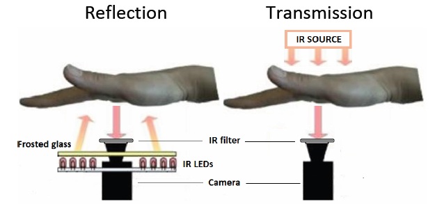
There are two methods for obtaining an image of a palm vein pattern. The method of reflection (Reflection) allows you to place all the components of the device in a single package, thereby reducing the size. It also reduces the psychological barrier (no need to put your hand anywhere). The method of transmitting IR light (Transmission) is to install the IR light from the back of the palm, and the camera with the filter is installed from the palm and receives IR radiation passing through the entire palm. Using the transmission method, the resulting images are more detailed.
Iron
The method of reflection was chosen as the basis for obtaining images of the palm vein pattern. To begin with, a preliminary device model was scribbled on a piece of paper. It should measure the distance from the device itself to the palm of the identified one, measure the temperature of the surface of the hand (for statistics, I wanted to have this functionality), turn on and off the IR illumination. As a camera, he stopped on a Logitech B910 webcam. Testing models of the device, and there were as many as 4, revealed the shortcomings of the three previous chambers. The first model was with a camera LinkSprite JPEG Color Camera TTL Interface . The process of transferring images to a PC was limited by the speed of the port, I had to give it up. Also 2 more noname webcams were checked, but the resulting images were of very poor quality. Further I will describe only the latest model.
A list of components has been compiled:
- Arduino Project Enclosure - a small package for Arduino projects
- Infrared Thermometer - MLX90614 - IR Thermometer
- USB HUB - for connecting the camera and arduino to one cable
- ORduino Nano - ATMega168
- Infrared Proximity Sensor - Sharp GP2Y0A21YK - IR distance sensor (from 10 to 80cm)
- Logitech B910 HD Webcam
- 2 transistors
- 2 4.7kΩ resistors, 6-470Ω
- 6 IR diodes 850nm
- Phototransistor (for measuring the illumination of the device with extraneous light, did not participate in the experiments, but was planned)
- USB B connector
- IR Filter 850nm
- Usb cable
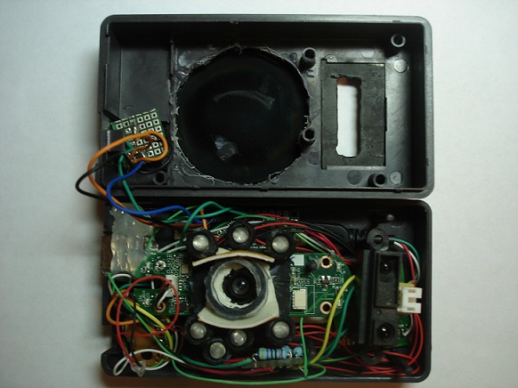
Connection diagram here (with physics / electrical engineering on you, I can not vouch for the consequences). The assembly process consisted in cutting out a smaller diameter circle in the center of the case than the IR filter. Then the filter was glued to the glue (super-moment). At first, instead of the super-moment, I used a glue gun, but the camera was very hot (the Logitech B910 feature) and the glue was no longer held. Cut a hole for the infrared thermometer. Also out of the box from the IR filter was made "mount" for the distance sensor. The camera was disassembled and minimized due to the removal of the case and frame, leaving only the board. The infrared filter that did not pass the infrared rays was removed from the camera lens (the process of removing the filter can be found here ). Next, the camera was also installed on the bottom of the case with glue. Around the camera symmetrically installed IR diodes. So that there is no illumination from the diodes on the camera lens, from the lens it has grown from the remnants of the case and double-sided tape, something like a casing to an IR filter.
Assembly:
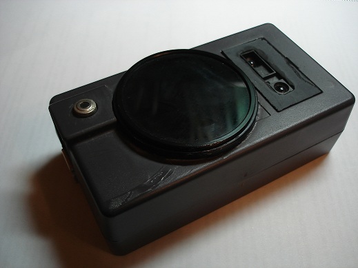
In the assembly, the device has the form:
BY
Arduino
All components of the device (except the camera) should be controlled by the arduino. This is a distance sensor, temperature sensor and IR illumination. In the aggregate, the algorithm works as follows:
- a command is received from the PC to start the operation of the distance sensor and the temperature sensor with the subsequent output of their values to the port
- as soon as the sensor value coincides with the entered values in the PC, the distance sensor turns off (its beam makes the light on the received images)
Further, if the values match:
- IR illuminator turns on
- take a picture
- turn off IR illumination
- transition to the initial stage
PC
Images received from the device should be further processed and recognized. Matlab software was chosen for writing PC software. As a recognition tool, the standard Matlab Neural Network Toolbox component was used. But before submitting images for learning and recognition, they need to be processed, namely, to highlight the main features.
Received images from the device:
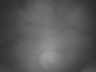
Can you imagine what were the pictures from previous models? Yes, not so hot.
Then there were attempts to improve the image for the selection of veins, searches for filters. It is hard to do when you do not know how, something worked out, something did not. But stumbled on the site pudn.com on the algorithm for the selection of veins flashed hope. In order to download it, you had to first share some of your own work. I had to send a lab made in a matlab using phase math (fuzzy logic). A day later I received a letter with the ability to download (40 points). The algorithm was written by a student from under heaven (thanks to you, whoever you are).
After adjusting the algorithm for yourself:
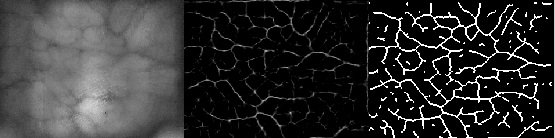
Not bad, huh? This is the same image, but already something. Now it remains to fill the base with reference images and train the network. After learning, it turned out that the invariance of the images is very small. It turned out that the veins on my arm are distinctly different, and on some hands the quality of the images, to put it mildly, is “not very”. 100 reference images were collected for each hand. Noise and hands-free images (elbows, fists, etc.) were used as negative samples. The sample included the hands of two people.
After training, we started to check the device. Errors of the second kind have a place to be. I had to reduce the threshold of coincidence with the standards. As a result, sometimes there were false passes. In practice, errors of the second kind occurred due to improper positioning of the hand in front of the device, or due to the blurring of the resulting images due to the movement of the hands. There was not enough time for experiments.
findings
Here you can only say that the topic is interesting and it is not fully revealed due to lack of time and necessary skills. I also did not have time to check the device for "inanimate comparisons". The phototransistor (for adjusting the camera under the illumination) and the temperature sensor (although the information from it was obtained, but was not taken into account) was not involved.
There are source codes for arduino and matlab, but it is embarrassing to show it, for I wrote / rewrote it in a hurry to be in time, reworking the device at the same time.
Sources used
- Physics of Life / Physics of Life / A. Nadort, Amsterdam: 2007. 177 p.
- Fuksis, R. Palm. It is an ACM Workshop on Multimedia and Security. R. Fuksis, M. Pudzs, M. Greitans, - Rome, 2009. - 27 p.
Source: https://habr.com/ru/post/149424/
All Articles