Repair of BP FSP Epsilon 1010, principle of work of APFC
The idea to write was born after the next unexpected breakdown of the power supply, in order to share the experience and where it was most to read next time, if a similar power supply (hereinafter referred to as the PSU) gets repaired or we need to recall the scheme.
I’ll say right away that the article is intended for a simple PC user, although it was possible to delve into academic details.
Despite the fact that the schemes are not mine, I give a description solely “from myself”, which does not pretend not to be the only correct one, but is intended to explain “on the fingers” the work of a much-needed device, like a computer's power supply unit.
')
I had to understand the work of APFC in 2005, when I had a problem with arbitrary rebooting of the computer. I bought a computer on a soapy firm without delving too deep into subtleties. The service did not help: the company works, and it reboots. I realized that it was the turn to tense myself ... It turned out the problem in the home network, which in the evening slipped in jumps up to 160V! He began to look for a circuit, to increase the capacity of input capacitors, slightly let it go, but did not solve the problem. In the process of searching for information, I saw in the prices incomprehensible letters APFC and PPFC in the block names. Later I found out that I had PPFC and I decided to buy myself a unit with APFC, then I also took a bespereboinik. Other problems started - knocking out a bespereboynik when you turn on the system unit and the network is lost, they throw up their hands in the service. I handed it back, I bought it 3 times more powerful, it still works without problems.
I will share with you my experience and I hope you will be interested to learn a little more about the system component - the power supply unit, which is unfairly assigned almost the last role in the computer.
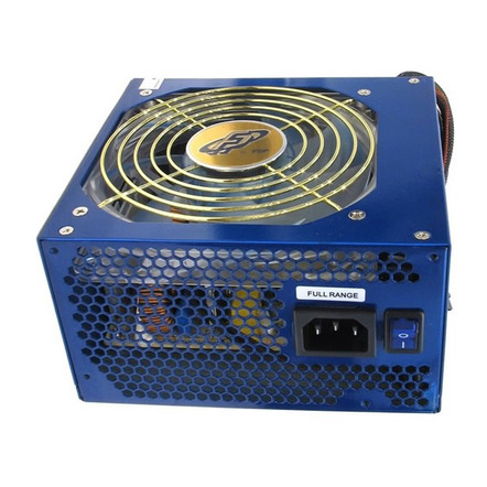
The FSP Epsilon 1010 power supplies are high-quality and reliable devices, but given the problems of our networks and other accidents, they sometimes also fail. It is a pity to throw out such a unit, and repairs may come close to the cost of a new one. But there are also trifles, eliminating which, you can bring it back to life.
How does the FSP Epsilon 1010:
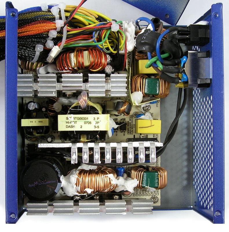
The most important thing is to understand the principle of operation and decompose the block into pieces.
I will give an example of fragments of schemes of the typical FSP Epsilon block that I found in nete. The schemes were compiled by hand by a very diligent and competent person who kindly put them in for general access:
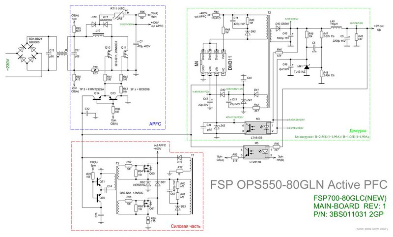
1. The main scheme:
Picture 1:
Link to full size: s54.radikal.ru/i144/1208/d8/cbca90320cd9.gif
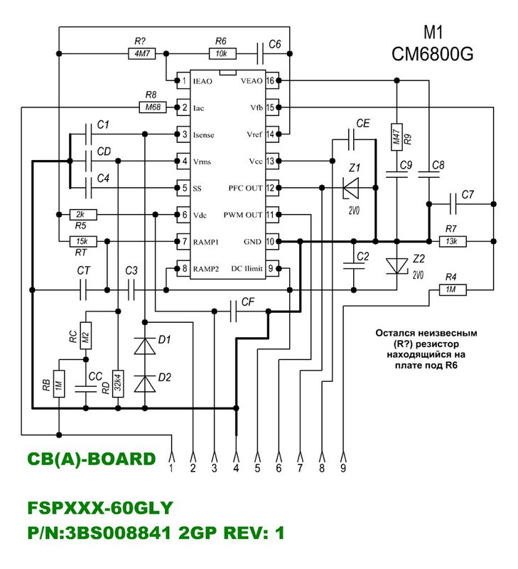
2. APFC controller circuit:
Figure 2:
Reference to full size: i082.radikal.ru/1208/88/0f01a4c58bfc.gif
Modifications of power units of this series differ in the number of elements (they are soldered additionally to the same board), but the principle of operation is the same.
APFC
So what is APFC?
PFC is power factor correction (PFC) - the process of reducing the consumption of the end device with a low power factor when powered from an AC power supply network to a state in which the power factor conforms to accepted standards. If you show it on three fingers, it looks like this:
- they started the power supply, the capacitors started charging - the peak of current consumption coincided with the peak of the sinusoid AC 220V 50Hz (too lazy to draw). Why coinciding? And how will they charge at “0” volts closer to the time axis? No The peaks will be in each half-wave of the sine wave, as the diode bridge is in front of the capacitor.
- the load of the unit pulled the current and discharged the capacitors;
- capacitors began to charge and peaks of current consumption appeared at the peaks of the sinusoid again.
Moreover, we see a “hedgehog” with which a sinusoid is overgrown, and which, instead of constant consumption, “pulls” the current in short jumps at narrow points in time. And what's so terrible, do not bother yourself, you say. And here the Baskervilles dog rummaged: these peaks overload the electrical wiring and can even lead to a fire with a nominally calculated cross section of the wires. And if you consider that the unit in the network is not one? Yes, and working in the same network, electronic devices are unlikely to enjoy such a "popilenny" network with interference. Moreover, with the declared power rating of the PSU, you will pay more for the light, since your network wires in the apartment (office) already act as a load. There is a task to bring down the current consumption peaks in time in the direction of the dips of the sinusoid, that is, to approach the similarity of linearity and unload the wiring.
PPFC - passive power factor correction. This means that before a single power supply line of the power supply there is a massive choke, the task of which is to knock down the current consumption peaks during the charging of capacitors, taking into account the nonlinear properties of the choke (meaning that the current through it lags behind the voltage applied to it - remember the school). It looks like this: at the maximum of the sine wave the capacitor should be charged and he is waiting for this, but what a bad luck - a choke was placed in front of him. But the choke is not entirely concerned about the need for a capacitor - a voltage is applied to it and a self-induction current arises, which is directed in the opposite direction. Thus, the choke prevents the capacitor from charging at the peak of the input sinusoid — the peak is in the network, and the capacitor is discharged. Strange, right? Isn’t this what we wanted? Now the sinusoid drops, but the throttle behaves like most people here: (we have - we don’t appreciate, we lose - we regret) the self-induction current only appears that already coincides with the decreasing current, which charges the capacitor. What we have: at the peak - nothing, at the failures - charge! Mission accomplished!
This is exactly how the PPFC scheme works by pulling in the peaks of current consumption on the dips of the sinusoid (ascending and descending parts) with just one choke. The power factor is close to 0.6. Not bad, but not perfect.
APFC - active power factor correction. This means using electronic components that require power. In this power supply, there are actually two power supplies: the first is the 410V stabilizer, the second is the usual classic switching power supply. This we consider below.
APFC and working principle.
Figure 3:
We have only come to the principle of the work of active power factor correction, so we will determine some points for ourselves right away. In addition to the main purpose (approximation to the linearity of current consumption over time), APFC solves the triune problem and has features:
- power supply with APFC consists of two blocks: the first - stabilizer 410V (actually APFC), the second - the usual classic switching power supply.
- APFC circuit provides a power factor of about 0.9. This is what we are striving for - “1”.
- APFC circuit operates at a frequency of about 200KHz. Agree, to pull the current 200,000 times per second with respect to 50 Hz - this is practically at each moment in time, that is, linearly.
- APFC circuit provides a stable constant output voltage of about 410B and works from 110 to 250V (in practice, from 40V). This means that the industrial network practically does not affect the operation of internal stabilizers.
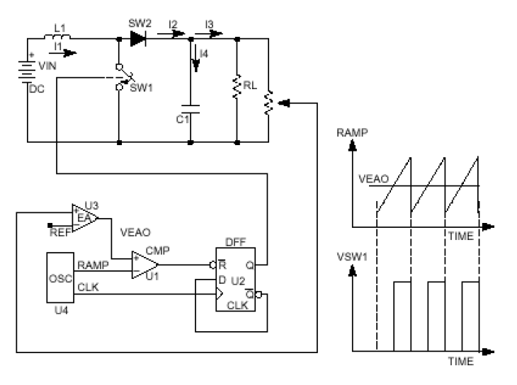
Work scheme:
The principle of operation of the APFC is based on the accumulation of energy in the choke and its subsequent return to the load.
When power is supplied through the choke, its current lags behind the voltage. When removing the voltage occurs the phenomenon of self-induction. This is what the power supply eats, and since the self-induction voltage can approach the double applied one, this is the 110V operation! The task of the APFC circuit is to dose the current through a choke with a given accuracy so that the output always has a voltage of 410V, regardless of the load and the input voltage.
In Figure 3, we see DC - a DC power source after the bridge (not stabilized), a cumulative choke L1, a transistor switch SW1, which is controlled by a comparator and PWM. The scheme is made quite boldly at first glance, since the key actually makes a short circuit in the outlet at the time of opening, but we will forgive it, given that the circuit occurs for microseconds with a frequency of 200,000 times a second. But if the key management scheme fails, you will surely hear and even smell, and maybe you will see how the power keys will burn in such a scheme.
1. Transistor SW1 is open, the current to the load flows as before through the choke from "+ DC" - "L1" - "SW2" - "RL" to "-DC". But the choke resists the movement of current (self-induction started), while there is an accumulation of energy in the choke L1 - the voltage rises almost to DC voltage, since this is a short circuit (though for a fraction of the time (everything is fine). The diode SW2 prevents the capacitor C1 from discharging at the time of opening of the transistor.
2. Transistor SW1 is closed ... the voltage on the load will be equal to the sum of the voltages of the source DC1 and the inductor L1, which has just non-sourly attached to the source and threw out the current of self-induction with reverse polarity. The disappearing magnetic field of the choke will cross it, inducing an emf of self-induction of opposite polarity on it. Now the self-induction current has one direction with the source current dropping (self-induction end). Self-induction is the phenomenon of induced emf in an electrical circuit as a result of a change in current.
So, at the moment of self-induction after the transistor is closed, our additive is obtained up to 410V due to the addition of energy from the choke. Why supplement? Remember the school, how much will be at the output of the bridge with a capacitor, if the input 220V? That's right, 220V multiplied by the root of two (1.41421356) = 311V. That would be without the work of the APFC scheme. It is exactly at the point where we are waiting for 410V, while only the + 5V standby is working and the unit itself is not running. Now it makes no sense to drive the APFC, the duty room, and so enough of its 2 amps.
All this is strictly controlled by the control circuit using feedback from the 410V point. The level of self-induction is controlled by the opening time of the transistors, that is, the energy accumulation time L1 is the pulse-width stabilization. The task of the APFC is to stably keep 410V at the output when the external factors of the network and the load change.
So it turns out that in the power supply unit with APFC there are two power supply units: the 410V stabilizer and the classic power supply itself.
Bringing the dependence of the peaks of current consumption from the peaks of the sinusoid is ensured by transferring these peaks to the frequency of operation of the APFC circuit 200,000 times per second, which approaches the linear current consumption at each time point of the 50 Hz 220 V sinusoid. Q.E.D.
Advantages of APFC:
- power factor of about 0.9;
- work from any whimsical network 110 - 250B, including unstable rural;
- noise immunity:
- high coefficient of stabilization of output voltages due to stable input 410V;
- low ripple output voltages;
- small filter sizes, as the frequency is about 200 kHz.
- high overall efficiency of the unit.
- small interference given to the industrial network;
- high economic effect in payment for light;
- electrical wiring is unloaded;
- at enterprises and in telecommunications organizations that have 60V station batteries, you can do without UPS at all for powering critical servers - simply turn on the unit in the 60V guaranteed power circuit without changing anything and not observing polarity (which is not). This will allow to get away from those unfortunate 15 minutes of work from the UPS up to 10 hours from the station batteries, so that the entire control system does not lie down if the diesel engine is not started. And many people do not pay attention to this or did not think about it until the diesel engine is offended somehow once ... All the equipment will continue to work, and there will be nothing to manage, since the computers are working out after 15 minutes. The manufacturer presents the range of work 90 - 265V due to the absence of such a power standard as variables 60B, but the practical limit of work was obtained at 40V, below it was not worth checking.
Re-read the item carefully again and evaluate the capabilities of their bespereboynik for critical servers!
APFC Disadvantages:
- price;
- Difficulty in diagnosis and repair;
- expensive parts (transistors - about $ 5 per piece, and they are there up to 5 pcs. Sometimes), often the cost of repair does not justify itself;
- Problems of working with bespereboynikami (UPS) due to the large starting current. Choose a UPS with a double power reserve.
And now we will consider the scheme of the power unit FSP Epsilon 1010 in fig. 12.
In the FSP Epsilon 1010, the power part of the APFC is represented by three HGTG20N60C3 transistors with a current of 45A and a voltage of 600V, standing in parallel: www.fairchildsemi.com/ds/HG/HGT1S20N60C3S.pdf
In our typical scheme there are 2 Q10, Q11, but this does not change the essence. Our unit is just more powerful. The FPC OUT signal goes from the 12th leg of the CM6800G chip to the 12th pin of the control module in Figure 2. Further through the resistor R8 for the keys locks. This is the management of APFC. The APFC control circuit is powered by + 15V duty rooms via optocoupler M5, resistor R82 - 8pin CB (A). But it starts only after the unit is started on the load by the PW-ON signal (green wire of the 24-pin connector to the ground).
Typical faults:
Symptoms:
- fuse blows with a clap;
- the unit “does not breathe” at all even after replacing the fuse, which is even worse. So damage threatens to turn into more expensive repairs.
Diagnosis: failure of the APFC circuit.
Treatment:
It is difficult to make a mistake in diagnosing the failure of the APFC circuit.
It is considered that a block with APFC can be started without APFC if it fails. And we will calculate it, and even check it out, especially when it comes to dangerous experiments with expensive HGT1S20N60C3S transistors. Solder transistors.
The unit works well if the problem was only in the APFC scheme, but you need to understand that the power supply will lose power up to 30% and it cannot be put into operation - only the test. Well, then we already change the transistors to new ones, but turn on the unit in series through a heat lamp 220V 100W. The unit is loaded for example on the old HDD. If the lamp burns in the floor and the HDD starts up (we touch it with our fingers), a fan is spinning on the unit - there is a possibility that the repair is complete. We start without a lamp with a fuse reduced by 3 times. And now is not burned? Well, then we solder our native F1 and go ahead to the hourly test under the equivalent watt load of 300-500! A lamp burning with full heat tells you about the full opening of the key transistors or their quiescent state, we are looking for a problem in front of them.
If at some stage no luck, we return to the new purchase of transistors, while not forgetting to buy the CM6800G controller. We change the details, we repeat everything again. Do not forget to visually inspect the entire board!
Symptoms:
- the block is launched once or when it has been connected to the network for 5 minutes;
- you have got a faulty HDD from anywhere;
- the fans are spinning, but the system does not boot, the BIOS does not peep at startup;
- condensed condensers on the motherboard, video card;
- the system randomly reboots, freezes.
Diagnosis: dried electrolytic capacitors.
Treatment:
- disassemble the unit and visually find bloated capacitors;
- The best solution is to change everything to new ones, and not just bloated ones;
Non-starting occurs due to the dried capacitors of the C43, C44, C45, C49 duty receptacles;
Component failures occur due to increased ripple in the + 5V, + 12V circuit due to the drying of filter condensates.
Symptoms:
- the unit whistles or beeps;
- the whistle tone changes under load;
- the unit whistles only while it is cold or while it is hot.
Diagnosis: PCB cracks or missed elements.
Treatment:
- parse the block;
- visually inspect the printed circuit board at the soldering points of the key transistors and filter chokes for oval cracks at the soldering point;
- if you didn’t find anything, then all the same you take away the legs of the power elements.
- check and enjoy the silence.
The rest of the faults are great, up to internal breaks or inter-turn breakdowns, cracks in the board and parts, and so on. Temperature problems are especially annoying when running until it warms up or cools down.
Power supplies from other manufacturers have a similar principle of operation, which will allow to find and fix the problem.
At the end of a couple of tips on BP:
1. Never unplug a powered APFC power supply! First, park the system, and then unplug it or turn it off without an extension cord - otherwise you will lose it ...
When the voltage drops at the moment of operation of the unit, the arc stretches and sparks occur, which leads to a bunch of harmonics other than 50 Hz - this time, the voltage decreases and the APFC keys try to keep the output voltage stable while opening fully and for a longer time, causing even more current and the arc is two. This leads to the breakdown of open transistors by huge currents and uncontrolled voltage harmonics - these are three. It is easy to check if there is a desire. Personally, I have already checked ... now I wrote this article and spent $ 25 on repairs. You can also write your own. By the way, the FSP Epsilon 1010 button on the case does not disconnect the power cord, but the control system, while all the power elements remain energized - be careful! Therefore, if you really need to quickly turn off the computer, then do it with the power button on the unit - everything is thought out.
2. If you know in advance that you will work with bespereboynik, then buy a power supply with PPFC. This will save you from unnecessary problems.
In the story, I tried not to bring unnecessary graphs, charts, formulas and technical terms, so that on the fifth line I would not scare away the ordinary torturer of my PC, a deeper understanding of the basics of which power would prolong his uptime.
Now is the time to disassemble the system unit and determine the model of your power supply, at the same time and dust it out. You have already prevented one malfunction. Clean it will serve with gratitude longer.Grease the fan, it is also welcome.
Who read the article to the end - thanks to all!
Now your BP is safe.
I’ll say right away that the article is intended for a simple PC user, although it was possible to delve into academic details.
Despite the fact that the schemes are not mine, I give a description solely “from myself”, which does not pretend not to be the only correct one, but is intended to explain “on the fingers” the work of a much-needed device, like a computer's power supply unit.
')
I had to understand the work of APFC in 2005, when I had a problem with arbitrary rebooting of the computer. I bought a computer on a soapy firm without delving too deep into subtleties. The service did not help: the company works, and it reboots. I realized that it was the turn to tense myself ... It turned out the problem in the home network, which in the evening slipped in jumps up to 160V! He began to look for a circuit, to increase the capacity of input capacitors, slightly let it go, but did not solve the problem. In the process of searching for information, I saw in the prices incomprehensible letters APFC and PPFC in the block names. Later I found out that I had PPFC and I decided to buy myself a unit with APFC, then I also took a bespereboinik. Other problems started - knocking out a bespereboynik when you turn on the system unit and the network is lost, they throw up their hands in the service. I handed it back, I bought it 3 times more powerful, it still works without problems.
I will share with you my experience and I hope you will be interested to learn a little more about the system component - the power supply unit, which is unfairly assigned almost the last role in the computer.
The FSP Epsilon 1010 power supplies are high-quality and reliable devices, but given the problems of our networks and other accidents, they sometimes also fail. It is a pity to throw out such a unit, and repairs may come close to the cost of a new one. But there are also trifles, eliminating which, you can bring it back to life.
How does the FSP Epsilon 1010:
The most important thing is to understand the principle of operation and decompose the block into pieces.
I will give an example of fragments of schemes of the typical FSP Epsilon block that I found in nete. The schemes were compiled by hand by a very diligent and competent person who kindly put them in for general access:
1. The main scheme:
Picture 1:
Link to full size: s54.radikal.ru/i144/1208/d8/cbca90320cd9.gif
2. APFC controller circuit:
Figure 2:
Reference to full size: i082.radikal.ru/1208/88/0f01a4c58bfc.gif
Modifications of power units of this series differ in the number of elements (they are soldered additionally to the same board), but the principle of operation is the same.
APFC
So what is APFC?
PFC is power factor correction (PFC) - the process of reducing the consumption of the end device with a low power factor when powered from an AC power supply network to a state in which the power factor conforms to accepted standards. If you show it on three fingers, it looks like this:
- they started the power supply, the capacitors started charging - the peak of current consumption coincided with the peak of the sinusoid AC 220V 50Hz (too lazy to draw). Why coinciding? And how will they charge at “0” volts closer to the time axis? No The peaks will be in each half-wave of the sine wave, as the diode bridge is in front of the capacitor.
- the load of the unit pulled the current and discharged the capacitors;
- capacitors began to charge and peaks of current consumption appeared at the peaks of the sinusoid again.
Moreover, we see a “hedgehog” with which a sinusoid is overgrown, and which, instead of constant consumption, “pulls” the current in short jumps at narrow points in time. And what's so terrible, do not bother yourself, you say. And here the Baskervilles dog rummaged: these peaks overload the electrical wiring and can even lead to a fire with a nominally calculated cross section of the wires. And if you consider that the unit in the network is not one? Yes, and working in the same network, electronic devices are unlikely to enjoy such a "popilenny" network with interference. Moreover, with the declared power rating of the PSU, you will pay more for the light, since your network wires in the apartment (office) already act as a load. There is a task to bring down the current consumption peaks in time in the direction of the dips of the sinusoid, that is, to approach the similarity of linearity and unload the wiring.
PPFC - passive power factor correction. This means that before a single power supply line of the power supply there is a massive choke, the task of which is to knock down the current consumption peaks during the charging of capacitors, taking into account the nonlinear properties of the choke (meaning that the current through it lags behind the voltage applied to it - remember the school). It looks like this: at the maximum of the sine wave the capacitor should be charged and he is waiting for this, but what a bad luck - a choke was placed in front of him. But the choke is not entirely concerned about the need for a capacitor - a voltage is applied to it and a self-induction current arises, which is directed in the opposite direction. Thus, the choke prevents the capacitor from charging at the peak of the input sinusoid — the peak is in the network, and the capacitor is discharged. Strange, right? Isn’t this what we wanted? Now the sinusoid drops, but the throttle behaves like most people here: (we have - we don’t appreciate, we lose - we regret) the self-induction current only appears that already coincides with the decreasing current, which charges the capacitor. What we have: at the peak - nothing, at the failures - charge! Mission accomplished!
This is exactly how the PPFC scheme works by pulling in the peaks of current consumption on the dips of the sinusoid (ascending and descending parts) with just one choke. The power factor is close to 0.6. Not bad, but not perfect.
APFC - active power factor correction. This means using electronic components that require power. In this power supply, there are actually two power supplies: the first is the 410V stabilizer, the second is the usual classic switching power supply. This we consider below.
APFC and working principle.
Figure 3:
We have only come to the principle of the work of active power factor correction, so we will determine some points for ourselves right away. In addition to the main purpose (approximation to the linearity of current consumption over time), APFC solves the triune problem and has features:
- power supply with APFC consists of two blocks: the first - stabilizer 410V (actually APFC), the second - the usual classic switching power supply.
- APFC circuit provides a power factor of about 0.9. This is what we are striving for - “1”.
- APFC circuit operates at a frequency of about 200KHz. Agree, to pull the current 200,000 times per second with respect to 50 Hz - this is practically at each moment in time, that is, linearly.
- APFC circuit provides a stable constant output voltage of about 410B and works from 110 to 250V (in practice, from 40V). This means that the industrial network practically does not affect the operation of internal stabilizers.
Work scheme:
The principle of operation of the APFC is based on the accumulation of energy in the choke and its subsequent return to the load.
When power is supplied through the choke, its current lags behind the voltage. When removing the voltage occurs the phenomenon of self-induction. This is what the power supply eats, and since the self-induction voltage can approach the double applied one, this is the 110V operation! The task of the APFC circuit is to dose the current through a choke with a given accuracy so that the output always has a voltage of 410V, regardless of the load and the input voltage.
In Figure 3, we see DC - a DC power source after the bridge (not stabilized), a cumulative choke L1, a transistor switch SW1, which is controlled by a comparator and PWM. The scheme is made quite boldly at first glance, since the key actually makes a short circuit in the outlet at the time of opening, but we will forgive it, given that the circuit occurs for microseconds with a frequency of 200,000 times a second. But if the key management scheme fails, you will surely hear and even smell, and maybe you will see how the power keys will burn in such a scheme.
1. Transistor SW1 is open, the current to the load flows as before through the choke from "+ DC" - "L1" - "SW2" - "RL" to "-DC". But the choke resists the movement of current (self-induction started), while there is an accumulation of energy in the choke L1 - the voltage rises almost to DC voltage, since this is a short circuit (though for a fraction of the time (everything is fine). The diode SW2 prevents the capacitor C1 from discharging at the time of opening of the transistor.
2. Transistor SW1 is closed ... the voltage on the load will be equal to the sum of the voltages of the source DC1 and the inductor L1, which has just non-sourly attached to the source and threw out the current of self-induction with reverse polarity. The disappearing magnetic field of the choke will cross it, inducing an emf of self-induction of opposite polarity on it. Now the self-induction current has one direction with the source current dropping (self-induction end). Self-induction is the phenomenon of induced emf in an electrical circuit as a result of a change in current.
So, at the moment of self-induction after the transistor is closed, our additive is obtained up to 410V due to the addition of energy from the choke. Why supplement? Remember the school, how much will be at the output of the bridge with a capacitor, if the input 220V? That's right, 220V multiplied by the root of two (1.41421356) = 311V. That would be without the work of the APFC scheme. It is exactly at the point where we are waiting for 410V, while only the + 5V standby is working and the unit itself is not running. Now it makes no sense to drive the APFC, the duty room, and so enough of its 2 amps.
All this is strictly controlled by the control circuit using feedback from the 410V point. The level of self-induction is controlled by the opening time of the transistors, that is, the energy accumulation time L1 is the pulse-width stabilization. The task of the APFC is to stably keep 410V at the output when the external factors of the network and the load change.
So it turns out that in the power supply unit with APFC there are two power supply units: the 410V stabilizer and the classic power supply itself.
Bringing the dependence of the peaks of current consumption from the peaks of the sinusoid is ensured by transferring these peaks to the frequency of operation of the APFC circuit 200,000 times per second, which approaches the linear current consumption at each time point of the 50 Hz 220 V sinusoid. Q.E.D.
Advantages of APFC:
- power factor of about 0.9;
- work from any whimsical network 110 - 250B, including unstable rural;
- noise immunity:
- high coefficient of stabilization of output voltages due to stable input 410V;
- low ripple output voltages;
- small filter sizes, as the frequency is about 200 kHz.
- high overall efficiency of the unit.
- small interference given to the industrial network;
- high economic effect in payment for light;
- electrical wiring is unloaded;
- at enterprises and in telecommunications organizations that have 60V station batteries, you can do without UPS at all for powering critical servers - simply turn on the unit in the 60V guaranteed power circuit without changing anything and not observing polarity (which is not). This will allow to get away from those unfortunate 15 minutes of work from the UPS up to 10 hours from the station batteries, so that the entire control system does not lie down if the diesel engine is not started. And many people do not pay attention to this or did not think about it until the diesel engine is offended somehow once ... All the equipment will continue to work, and there will be nothing to manage, since the computers are working out after 15 minutes. The manufacturer presents the range of work 90 - 265V due to the absence of such a power standard as variables 60B, but the practical limit of work was obtained at 40V, below it was not worth checking.
Re-read the item carefully again and evaluate the capabilities of their bespereboynik for critical servers!
APFC Disadvantages:
- price;
- Difficulty in diagnosis and repair;
- expensive parts (transistors - about $ 5 per piece, and they are there up to 5 pcs. Sometimes), often the cost of repair does not justify itself;
- Problems of working with bespereboynikami (UPS) due to the large starting current. Choose a UPS with a double power reserve.
And now we will consider the scheme of the power unit FSP Epsilon 1010 in fig. 12.
In the FSP Epsilon 1010, the power part of the APFC is represented by three HGTG20N60C3 transistors with a current of 45A and a voltage of 600V, standing in parallel: www.fairchildsemi.com/ds/HG/HGT1S20N60C3S.pdf
In our typical scheme there are 2 Q10, Q11, but this does not change the essence. Our unit is just more powerful. The FPC OUT signal goes from the 12th leg of the CM6800G chip to the 12th pin of the control module in Figure 2. Further through the resistor R8 for the keys locks. This is the management of APFC. The APFC control circuit is powered by + 15V duty rooms via optocoupler M5, resistor R82 - 8pin CB (A). But it starts only after the unit is started on the load by the PW-ON signal (green wire of the 24-pin connector to the ground).
Typical faults:
Symptoms:
- fuse blows with a clap;
- the unit “does not breathe” at all even after replacing the fuse, which is even worse. So damage threatens to turn into more expensive repairs.
Diagnosis: failure of the APFC circuit.
Treatment:
It is difficult to make a mistake in diagnosing the failure of the APFC circuit.
It is considered that a block with APFC can be started without APFC if it fails. And we will calculate it, and even check it out, especially when it comes to dangerous experiments with expensive HGT1S20N60C3S transistors. Solder transistors.
The unit works well if the problem was only in the APFC scheme, but you need to understand that the power supply will lose power up to 30% and it cannot be put into operation - only the test. Well, then we already change the transistors to new ones, but turn on the unit in series through a heat lamp 220V 100W. The unit is loaded for example on the old HDD. If the lamp burns in the floor and the HDD starts up (we touch it with our fingers), a fan is spinning on the unit - there is a possibility that the repair is complete. We start without a lamp with a fuse reduced by 3 times. And now is not burned? Well, then we solder our native F1 and go ahead to the hourly test under the equivalent watt load of 300-500! A lamp burning with full heat tells you about the full opening of the key transistors or their quiescent state, we are looking for a problem in front of them.
If at some stage no luck, we return to the new purchase of transistors, while not forgetting to buy the CM6800G controller. We change the details, we repeat everything again. Do not forget to visually inspect the entire board!
Symptoms:
- the block is launched once or when it has been connected to the network for 5 minutes;
- you have got a faulty HDD from anywhere;
- the fans are spinning, but the system does not boot, the BIOS does not peep at startup;
- condensed condensers on the motherboard, video card;
- the system randomly reboots, freezes.
Diagnosis: dried electrolytic capacitors.
Treatment:
- disassemble the unit and visually find bloated capacitors;
- The best solution is to change everything to new ones, and not just bloated ones;
Non-starting occurs due to the dried capacitors of the C43, C44, C45, C49 duty receptacles;
Component failures occur due to increased ripple in the + 5V, + 12V circuit due to the drying of filter condensates.
Symptoms:
- the unit whistles or beeps;
- the whistle tone changes under load;
- the unit whistles only while it is cold or while it is hot.
Diagnosis: PCB cracks or missed elements.
Treatment:
- parse the block;
- visually inspect the printed circuit board at the soldering points of the key transistors and filter chokes for oval cracks at the soldering point;
- if you didn’t find anything, then all the same you take away the legs of the power elements.
- check and enjoy the silence.
The rest of the faults are great, up to internal breaks or inter-turn breakdowns, cracks in the board and parts, and so on. Temperature problems are especially annoying when running until it warms up or cools down.
Power supplies from other manufacturers have a similar principle of operation, which will allow to find and fix the problem.
At the end of a couple of tips on BP:
1. Never unplug a powered APFC power supply! First, park the system, and then unplug it or turn it off without an extension cord - otherwise you will lose it ...
When the voltage drops at the moment of operation of the unit, the arc stretches and sparks occur, which leads to a bunch of harmonics other than 50 Hz - this time, the voltage decreases and the APFC keys try to keep the output voltage stable while opening fully and for a longer time, causing even more current and the arc is two. This leads to the breakdown of open transistors by huge currents and uncontrolled voltage harmonics - these are three. It is easy to check if there is a desire. Personally, I have already checked ... now I wrote this article and spent $ 25 on repairs. You can also write your own. By the way, the FSP Epsilon 1010 button on the case does not disconnect the power cord, but the control system, while all the power elements remain energized - be careful! Therefore, if you really need to quickly turn off the computer, then do it with the power button on the unit - everything is thought out.
2. If you know in advance that you will work with bespereboynik, then buy a power supply with PPFC. This will save you from unnecessary problems.
In the story, I tried not to bring unnecessary graphs, charts, formulas and technical terms, so that on the fifth line I would not scare away the ordinary torturer of my PC, a deeper understanding of the basics of which power would prolong his uptime.
Now is the time to disassemble the system unit and determine the model of your power supply, at the same time and dust it out. You have already prevented one malfunction. Clean it will serve with gratitude longer.Grease the fan, it is also welcome.
Who read the article to the end - thanks to all!
Now your BP is safe.
Source: https://habr.com/ru/post/149259/
All Articles