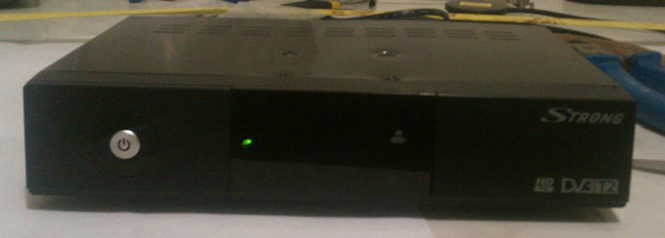
SRT 8500 Overheating Elimination
The other day, my grandfather received a SRT 8500 digital terrestrial receiver. Well, since this is the case - I connected the device, set it up - the picture quality is excellent ... but after about an hour of work, the device hung. I rebooted ... it does not even take a minute - again hang.
Receiver due to overheating (the presence of a power supply inside it) tightly hung.
Since my grandfather received this receiver free of charge from the state (Ukraine), it was decided not to try to give the receiver for warranty repair (especially since the intermediary would have to carry the device to Kiev, and it is unlikely that we would get something better) and improve it in order to deprive the identified deficiencies.
I had a goal to make changes to the device as soon as possible, with possible subsequent revision.
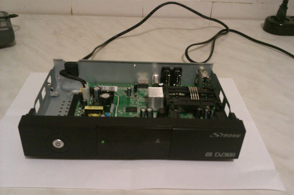
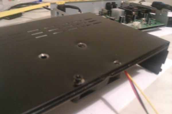
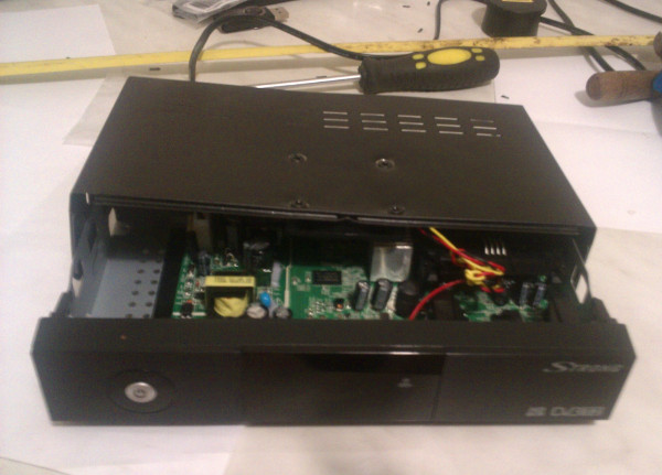
So, removing the top cover of the receiver, we see the following:
')
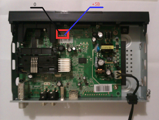
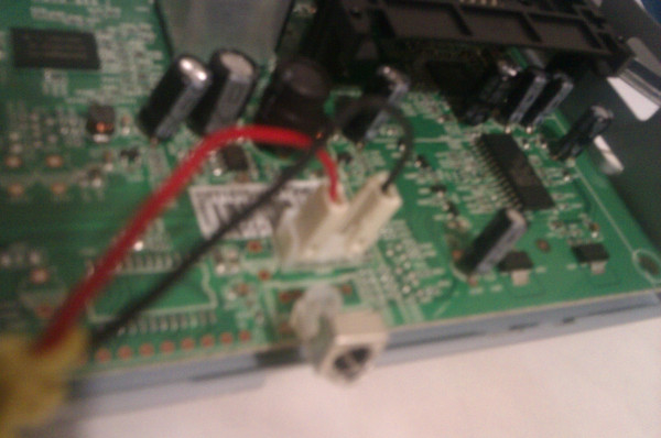
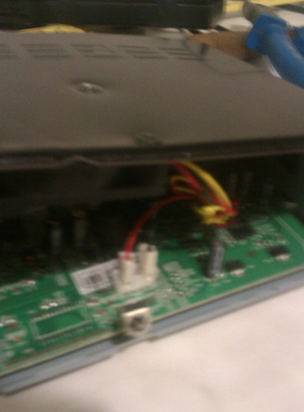
We are interested in a connector circled in a red rectangle, from here a fan will be powered to increase the intensity of air circulation. In Figure 2, two extreme outputs are marked with voltages of 0 and + 5V, respectively.
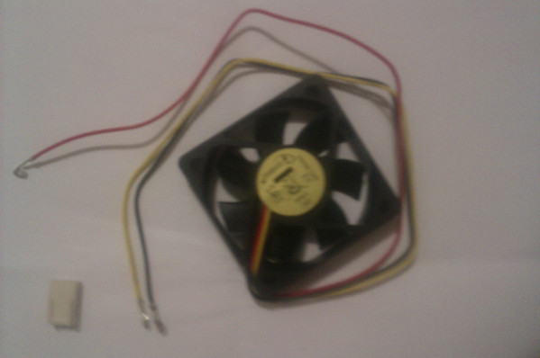
I took the fan with a low profile with a diameter of 2.5 inches (in the store this 35 UAH. == 145 rubles) - it fit the free space without any problems - without touching the inside of the device.
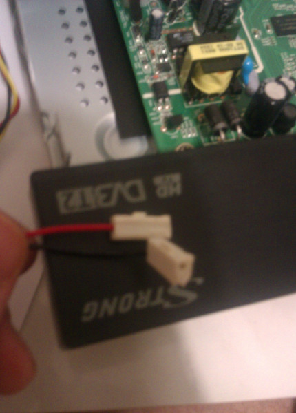
To connect the fan to the power connector, I first wanted to find the appropriate connector that matches the one on the device board. But the search for it in local stores was futile. Well, okay, we use what is available. It was decided to cut the fan power connector, consisting of three sections, in half, resulting in two connectors from it.
Here's what happened:
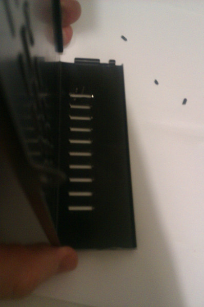
We take the blade and carefully cut the power connector on the receiver board so that both of the cooling fan connectors just made are well attached:
Well, the floor is done, let's start upgrading the top cover of the device.
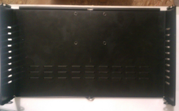
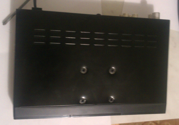
We will improve the ventilation holes on the sides of the lid - we will sell the ventilation slots extruded during stamping with a screwdriver:
Then we cut the resulting bulges with the nippers:
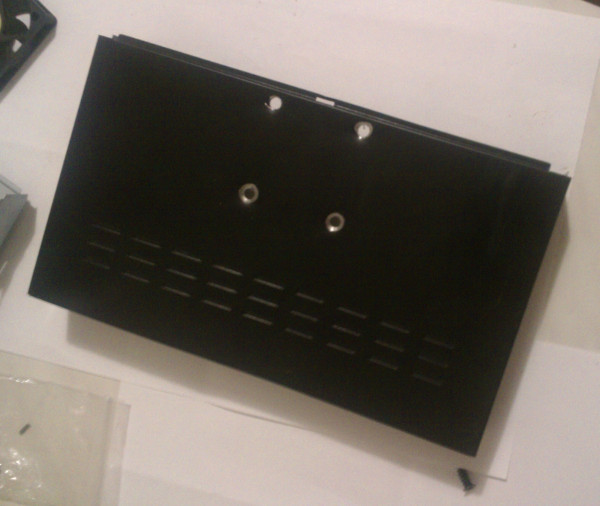
Put the cover on top in the bottom and mark the space for the holes. I made the holes as close as possible to the edge of the lid on its front side, since at this point the cooler can be positioned very well, it will not rest on the inside of the device.
Next, the matter is small - we drill holes for the screws for fastening the cooling fan.
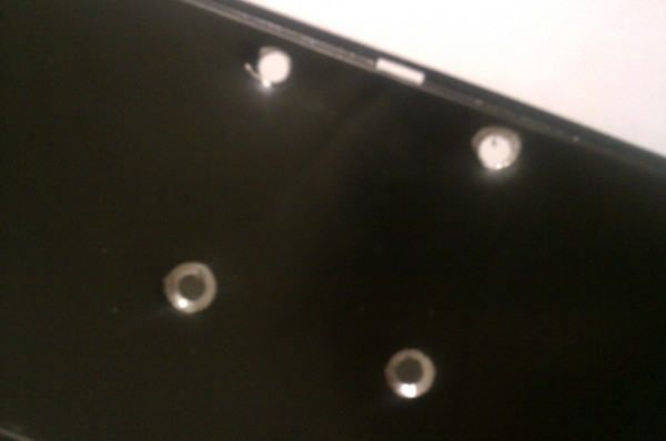
Well, after applying the cooler, we find that the holes on the lid and on the cooler are completely coincident. Now attach the cooler screws to the cover.
Then we connect our cooler to the power pins on the device board, as shown in fig. five.
After testing the device for an hour, I made sure that the device became much less heated.
The only thing that still needs to be done is to make a hole above the cooler in the lid and close the hole with protection against ingress of foreign objects inside the device, thereby improving ventilation.
Only HTC Explorer was at hand for photographing - so for the poor quality of photos - please understand and forgive.
Receiver due to overheating (the presence of a power supply inside it) tightly hung.
Since my grandfather received this receiver free of charge from the state (Ukraine), it was decided not to try to give the receiver for warranty repair (especially since the intermediary would have to carry the device to Kiev, and it is unlikely that we would get something better) and improve it in order to deprive the identified deficiencies.
I had a goal to make changes to the device as soon as possible, with possible subsequent revision.
So, removing the top cover of the receiver, we see the following:
Fig. one
')
Fig. 2
We are interested in a connector circled in a red rectangle, from here a fan will be powered to increase the intensity of air circulation. In Figure 2, two extreme outputs are marked with voltages of 0 and + 5V, respectively.
I took the fan with a low profile with a diameter of 2.5 inches (in the store this 35 UAH. == 145 rubles) - it fit the free space without any problems - without touching the inside of the device.
Fig. 3
To connect the fan to the power connector, I first wanted to find the appropriate connector that matches the one on the device board. But the search for it in local stores was futile. Well, okay, we use what is available. It was decided to cut the fan power connector, consisting of three sections, in half, resulting in two connectors from it.
Here's what happened:
Fig. four
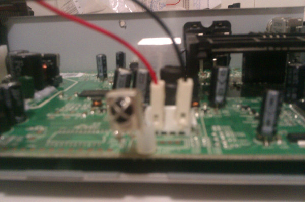
We take the blade and carefully cut the power connector on the receiver board so that both of the cooling fan connectors just made are well attached:
Fig. five
Fig. 6
Well, the floor is done, let's start upgrading the top cover of the device.
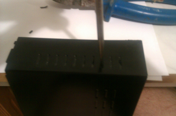
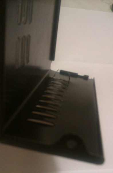
We will improve the ventilation holes on the sides of the lid - we will sell the ventilation slots extruded during stamping with a screwdriver:
Fig. 7
Then we cut the resulting bulges with the nippers:
Fig. eight
Fig. 9
Let's start preparing the holes for fastening the cooler to the top cover of the device.
Put the cover on top in the bottom and mark the space for the holes. I made the holes as close as possible to the edge of the lid on its front side, since at this point the cooler can be positioned very well, it will not rest on the inside of the device.
Fig. ten
Next, the matter is small - we drill holes for the screws for fastening the cooling fan.
Fig. eleven
Fig. 12
Well, after applying the cooler, we find that the holes on the lid and on the cooler are completely coincident. Now attach the cooler screws to the cover.
Fig. 13
Then we connect our cooler to the power pins on the device board, as shown in fig. five.
Now we will assemble the receiver and check its working capacity.
Fig. 14
Fig. 15
Fig. sixteen
Fig. 17
After testing the device for an hour, I made sure that the device became much less heated.
The only thing that still needs to be done is to make a hole above the cooler in the lid and close the hole with protection against ingress of foreign objects inside the device, thereby improving ventilation.
Only HTC Explorer was at hand for photographing - so for the poor quality of photos - please understand and forgive.
Source: https://habr.com/ru/post/149155/
All Articles