Ectognathus, hexapod robot on micro-servah with their own hands, part two
Good afternoon, dear habrovchane. This is the second part of an article about the development of a Hexapod robot. The first part you can find here .
In this article I will tell you directly about the production of the robot itself, the transition from the models in SolidWorks to the real device.
The first thing I would like to point out is that between the moment “well, everything, I have a model, the project is almost ready” and “I have a ready device on the table”, in fact, there are a lot of things. The faster you make this transition, the less likely the project will be abandoned. To this stage, the friend managed to absorb enthusiasm, so I continued the project alone.
After the model was completed, it was necessary to start, in fact, production, and the first thing that should have been done was to purchase the necessary parts. If there were no problems with servo drives and batteries, and by that time they were already on my desk, the search for everything else turned out to be less easy. I started with the bearings on the same screw that serves as the axis. Since I chose the screw M3, the bearings had to be found with the same inner diameter. And the easiest way to do this was to do it in the auto / air shop of models Therefore, I recommend to everyone who is looking for this kind of small parts to first explore the range of shops with modelkami, it turned out to be much easier than contacting stores that specialize in bearings.
I purchased a couple of such sets here: http://rc-go.ru/cat/product27455.htm - 4 bearings with an inner diameter of 3 mm, an outer one - 8 mm, and a height of 4 mm, costing 450r for 4 pieces.
Strangely enough, it was easy to find bearings, but to buy screws was much harder. The fact is that starting with the M3, the screws are sold at almost every corner, but the design was equipped with M2 screws - they fixed the “rocker” of the servo drives, and it was impossible to use the M3 there - they would simply turn the rocker. In ordinary stores there were no such screws, and fastener shops sold them only in thousands of pieces. Fortunately, I found a shop where you can buy even one screw. Despite the somewhat inconsistent name "Superbolt", the store turned out to be very good, where I immediately bought all the fasteners - M3 of different lengths with a hidden head, M2, nuts for them and washers.
Different racks I bought in the VoltMaster store.
In total, all this small things came out cheaper than 500 rubles.
Next, it was necessary to choose where and from what to mill the details, and it was here that trouble arose. They milled a lot of places, but they needed their own material everywhere, sheet aluminum 2 mm thick was either not there, or "it was once, but now it is over." New sheets were sold only in 1x3 meter format, which was, to put it mildly, a bit too much. I phoned five companies and nowhere were ready to sell the trim.
But, fortunately, I remembered that the former classmate has a milling machine. Having contacted him, I discussed the problem, and found out that he also didn’t have aluminum sheet, but there is a composite material called ALUCOBOND , which is a “puerbrod” of two thin layers of aluminum, between which some kind of polymer is enclosed. The thickness of this sandwich was 3 mm, and the density (and, accordingly, weight) was two times less than aluminum sheet!
Thus, after adjusting the density in the solid, the mass of the new model became about 650 grams.
By the way, a couple of days ago I found out that in one of the firms you can still buy aluminum trim, so if you absolutely need duralumin, then sometimes you can still find it, but you need to look hard.
After everything needed was purchased, it was time to move on to the next stage.
')
And now I will tell you about the most important. On the rake, which can occur during production. Rakes, which translate into additional costs.
Well, firstly, if this is your first project ... Yes, even if not the first, I still recommend cutting / milling to order not from large firms but from small private owners, if the design is not yet debugged. Because it is very unlikely that in a large firm you will be allowed to sit side by side and, having seen that the first part does not fit in with your drives, shout “stop the frezer footer !!!”.
Since I milled a group mate, I had such an opportunity. We agreed to cut a few test parts first, check them, and then, if everything goes well, cut out the rest. Of course, the test parts did not fit, so I had to edit them on the go and re-cut them again.
So what is worth paying attention to?
After I adjusted the construction several times, the shoals finally disappeared, and I received a package of my items, from which I began to assemble Ectognatus.
At the assembly stage, there was no special rake. I will note only two things.
This is what a freshly milled part looked like.
Leg assembly, design verification.
Model and real torso of the robot
Model and real servo node
Ectognatus assembly
So, after the whole structure has been assembled, it's time to check it in action.
Before designing custom electronics, I wanted to check how it behaves in the real world, current consumption, etc. For verification, it was decided to use the Mini-STM32 board, which I already mentioned in the corresponding article .
Since it is impossible to power electronics and drives from a battery without a converter, batteries have so far been left out of work, in construction, but unconnected.
For the test, I chose the following path: a switching board is made from the layout, to which all the drives are connected - the power and ground are separated into 18 drives, and their signal inputs are grouped into three pieces (one leg). Mini-STM32 connects to this board with wires with sockets ( like these ).
Since there were a lot of channels (18 pieces!) And the frequencies there were about 50 hertz, there was no point in chasing hardware SHIM, only to look for hemorrhoids. Therefore, the signal inputs from the drives I hung on the usual free GPIO. A radio module with a chip from Nordic was connected to the SPI controller, which I never cease to admire: http://www.ebay.com/itm/1pcs-NRF24L01-2-4GHz-Antenna-Wireless-Transceiver-Module-For-Microcontr-/ 261072511055
Since at one time I wrote a driver for FreeRTOS for it, working on interraps and DMA and not just a pollingue, I brought this FreeRTOS to the board.
In fact, it turned out to be a radio-controlled 18-channel PWM generator. From the point of view of the software, there are no special tricks, except for the driver for the radio module. PWM is generated using one timer, using the same method as in this article from DIHALT
There is an array of 18 structures
Where * PinAddress - bitband address management of the selected foot. The array is sorted in ascending order by the DutyCycle , the DutyCycle of the first element is entered into the Capture-Compare register, and in the interrupt by coincidence of the timer, the level of the corresponding pin is set through PinAdress . After that, the DutyCycle of the following is entered into the SS register. When the timer reaches the maximum, all the pins are set to 1, the array is re-sorted (in case new values arrive), and everything repeats. So that the received values do not knock down the generation, they are entered into the new Work array, and at the time the timer overflows, the Work and Sorted arrays are swapped — thus, we get double buffering.
To communicate with the computer using the same board, with the same radio module connected via USB. In it, I implemented a HID device, so the data is sent to it elementary, without additional drivers, from any convenient programming language. My control program, for example, on C #. Of course, the transmitter is controlled by FreeRTOS, in order not to have to rewrite the module driver. Information transfer to the robot goes in one task, data exchange with USB - in others. Even if nothing new came through USB, the transmitter constantly “pings” the robot, sending it a packet with the appropriate header. Since the aknolage of the radio modules is hardware, you can immediately find out if there is a connection with the robot or not, and set yourself the corresponding byte in status. USB task as a report sends exactly this status.
If new data arrived (angles for 18 drives, raw, no frills), then USB-task puts them in the queue for the transmission, and the transmitter-task in the same raw form sends them to the robot, which, on receipt, enters them in the already mentioned array Work.
Thus, all the logic can be implemented on a computer - only the duty ratio of the drives will be transferred to the robot.
Of course, in the future this will be implemented differently, but for testing it is the best way possible - it is not necessary to alter the glands a hundred times.

The prog program written in half a day cannot boast, of course, but in principle it performs its functions. So far, no IR, only forward kinematics for drawing models and trite forehead sequences for movements.
After everything described above was done, I recorded several sequences to Ectognatus, which he reproduced in this video:
The wires connected to it are powered by the LBP, for the reason of the absence of the converter already described above.
So, it's time to talk about the most important thing. All rakes rakes all shoals jamb.
Do you know what the check showed? The robot barely stood. He could somehow keep his weight on six legs, but it was enough to lift two, and he fell on this side. Seen me very, very much upset. Hands straight down. I sat and thought, “did my rough calculations turn out to be so erroneous that the robot cannot hold on?”. I took it "floor" with batteries - instead of 650-700 grams Ectogatnus began to weigh 500-550. After that, he reluctantly portrayed his willingness to work - the video above was captured under these conditions. But how so? And then I thought - “maybe something is wrong with the drives?” And decided to measure the time declared by the manufacturer. It was here that the rake, which so painfully sounded on my forehead, came to light.
Like all the rakes, they consisted of two parts - the one on which you are attacking, a small metal one, and one that severely hits the forehead.
The metal part of the rake was the fact that manufacturers produce two types of drives, the MG90 and MG90S. They differ somewhat in parameters and design.
Here is the MG90S, the ones that I bought:

Weight: 13.4g
Dimension: 22.8 * 12.2 * 28.5mm
Stall torque: 1.8kg / cm (4.8V) - 2.2kg / cm (6.0V)
Operating speed: 0.10sec / 60degree (4.8v) - 0.08sec / 60degree (6.0V)
Operating voltage: 4.8-6.0V
But MG90:
Pay attention to the protrusion from the bottom of the drive (which I called “asshole”, because in this situation it was it, without getting up into the design). In the drawing it is perfectly visible:

But its parameters:
Weight: 14g
Dimension: 23.1 * 12.2 * 29.0mm
Stall torque: 2.2kg / cm (4.8V) - 2.5kg / cm (6.0V)
Operating speed: 0.11sec / 60degree (4.8v) - 0.10sec / 60degree (6.0V)
Operating voltage: 4.8-6.0V
Notice the difference? A little slower and a little stronger. Well, well, I stepped on this part of the rake myself - I had to take, of course, MG90, which are stronger. However, they didn’t get up to the design only if they tried to install both in the servo-mount (to tell the truth, not because of the “assholes” but because they were a little higher in height than the length, but designed for square drives). But with the MG90S, he got up in the mount like a glove, without any problems. This suited me perfectly, since the weak MG90S remained only as a turning serf, on which there was almost no load. A servos, which accounted for all the weight easily replaced by MG90.
And now we turn to the rake handle. Big and heavy. So, how do normal people perceive Stall Torque? Obviously, like this: “If Stall Torque is set to X * Y, then when we hang at a distance X from the axis of the servo a weight of less than Y, the server will be able to lift this load. If the mass is about Y, then the server will be able to hold it, but it will not be able to lift it anymore. ”
For expensive and good drives this is true - however, it still does not interfere with checking. But the Chinese comrades perceive this parameter differently. It is practically not connected with the real moment. I do not exaggerate, it means that for one MG90S the moment can be three times less than stated, for another - three and a half. For MG90 - two. Etc. That is, there is not even a linear relationship, you can not just "divide by three", let's say.
But let's detail. I decided to measure the moment of my drives. To do this, you can use a simple device - a container in which we will pour water, something that will serve as a shoulder and measuring cup. As a shoulder, I took the horizontal part of the leg of the robot, 6 cm long. Thus, I expected that the servant would be able to raise the capacity from 300 ml of water while feeding the pot 5B of the source. The moment in this case would be equal to 0.3 * 6 = 1.8 kg * cm. The container was a liter juice bag, from which I cut off the top and through which I passed a strong wire instead of a pen. If you repeat this at home, make sure that the bag itself and the handle hold tight, otherwise you can pour all the equipment. The shoulder is screwed to the servo drive, the package is hung on the second end of the shoulder, a small program gives the minimum value of the angle of rotation, which is replaced by the maximum when you press the button. In this case, the serv tries to raise the load from the lowest to the highest position. By the amount of water we determine the weight of the load, and hence the moment acting on the servu. The moment at which the server can no longer lift the load, but it will lift with a slight decrease and there will be a Stall Torque.
What I saw in the end: 300 ml (moment 1.8) - the server does not move. Well, the moment is overstated, it is expected. But in my opinion, I had a large supply, how much did they overstate it? We continue to measure.
250 ml (moment 1.5) - almost does not move.
150 ml (moment 0.9) - rises slightly, does not even reach the middle
100 ml (moment 0.6) - almost reaches the middle
~ 90 ml (time 0.54) - raises the load.
Honestly, I didn’t believe my eyes - I understand that it is possible to overstate the figures, but more than three times ... Maybe this is such a serv? But no, I measured all 20 pieces that I ordered.
As a result, two thirds behaved as described above, one third was even weaker (as far as I did not find out). In addition, there was a strong variation in PWM, that is, for one serf, the extreme rotation was at the duty cycle, say 0x200 (the value of the timer register), for the other - 0x1E5, and so on.
But it is not all that bad. I ordered 20 MG90 drives, those with an asshole and stronger. The results of the measurements were more rosy - at the stated moment 2.2 they gave out about 1.2.
That is, the characteristics were overestimated not only three, but only two times. Well, and still there were those that turned out to be weaker than the others, but still it was no longer so critical.
I remind you that MG90 is only 1.2 times stronger than MG90S by the parameters stated on the website, but in reality MG90 is more than twice as large as MG90S. In addition, they turned out to be noticeably quieter and less prone to oscillations around the setpoint - hi to the MGIDS PID regulator.
The conclusion from this is this: never believe the infe received from Chinese manufacturers, if you don’t want to later discover that the parameters on the site are related to real ones only through the phase of the moon and the astral twists. Before development, do not spare money for 1-2 drives, count its real time, consumption, speed. It will be cheaper than re-ordering the entire batch. Well, if you buy Chinese drives - take a reserve necessarily. It’s not only that a third turned out to be even weaker, but also that one was generally broken (it jerked terribly, apparently there was something wrong with its regulator), the pair burned down from the strain and another blew off the gear with motor shaft.
However, those that I purchased the second time, MG90, I am quite pleased. As a result, the robot rose quietly along with the batteries, absolutely calmly could lift its legs without fear of falling, and even could rise from the “unfolded” position (as on the video) in one motion, purely due to the strength of the servos, without propping up previously, with the tips of the legs.
It was at this moment that I paused. Well, more precisely, I didn’t stop at all, but slowed down the pace of development, since my vacation ended and a lot of work began. Now I am in the process of designing custom electronics for a robot, about which I will say a few words in the article.
First of all, you need to design a serious enough converter that can deliver 30W to the drives. I found a very entertaining chip, which, according to International Rectifier's assurances, is capable of providing DC-DC conversion from 11.1V to 6V x 10A without a radiator, despite the fact that it does not need external mosfets - only a power choke.
Here it is, darling: http://www.irf.com/product-info/datasheets/data/ir3475m.pdf
10A drives, of course, will not pull - the maximum I saw when all drives are locked, and the robot is trying hard to get up - about 6A. So mikruhi should be enough. But this is in theory, in practice, I never used it - if someone worked with her, share your impressions.
I leave the calculator STMk, about the same as on the debug, and, in the distant future, I will push the inverse kinematics into it.
Initially, the connection was planned to be left on these radio modules - they are convenient, I have already written firewood for them, there is a version that is fully compatible with pins, but with an heaving amp, which is half a kilometer away. And I planned to put the camera on the roof of the robot. Of course, in order not to do useless work on getting a “raw” signal from the camera, and sending it over this module (which does not have enough speed to send normal video), I planned to take a camera with a built-in transmitter, for example, such .
On the other side, a rather dimensional receiver is placed, and since the output from it is analog, a usb device is added here that allows you to connect analog video sources to your computer. And, in principle, I have already come to terms with this, but then I saw him .
Router TL-MR3020. Miracle of Chinese technology for 800 rubles. Outwardly very similar to the Apple device.
Internally - a full-fledged comp with Linux, which has long been ported to OpenWRT.

The board inside it is only 5.7x5.7 cm. And it has a USB host!
Its consumption, even with the harshest transmission, does not exceed 180 mA, and the average is about 100.
As it turned out, this router (and its full analogue, just intended for the domestic Chinese market, TL-WR703N, about which most articles are written, if you search, search by this title) has long been used by electronic engineers as a single board computer, which can be used in their handicrafts. It easily and naturally rises normal video streaming, you can easily connect it to a regular webcam.
More similar about TL-MR3020 and his twin brother TL-WR703N can be read on the website OpenWRT
At work, I am picking it up just now, so I had the good fortune to work with him live.
So now my plan is this - on my board there is a converter that provides power to all the nodes of the circuit, STMka, which acts as a controller for all mechanics (legs and pivotal serva on the roof, turning the camera), and, perhaps, a couple of sensors — say, an accelerometer, to watch your tilt. On this board, a board from TL-MR3020 is placed on top, with OpenWRT on board, which provides streaming video and the connection of the robot with a computer via Wi-Fi. Previously, extra connectors are removed from it, of course - there is nothing to occupy space. It will also be connected to my board via USB, the board with the controller of the legs will be introduced by a HID device. Thus, we get rid of the bulky analog video receiver, the converter that comes with it, the separate transceiver module to the computer, and we are able to steer the robot from any device with Wi-Fi, while simultaneously watching through its camera, for example - from an iPad.
I have everything on this for now, as soon as there is time and I’m completing the fees and getting results, wait for the next article.
Thanks for attention!
In this article I will tell you directly about the production of the robot itself, the transition from the models in SolidWorks to the real device.
Start of production
The first thing I would like to point out is that between the moment “well, everything, I have a model, the project is almost ready” and “I have a ready device on the table”, in fact, there are a lot of things. The faster you make this transition, the less likely the project will be abandoned. To this stage, the friend managed to absorb enthusiasm, so I continued the project alone.
After the model was completed, it was necessary to start, in fact, production, and the first thing that should have been done was to purchase the necessary parts. If there were no problems with servo drives and batteries, and by that time they were already on my desk, the search for everything else turned out to be less easy. I started with the bearings on the same screw that serves as the axis. Since I chose the screw M3, the bearings had to be found with the same inner diameter. And the easiest way to do this was to do it in the auto / air shop of models Therefore, I recommend to everyone who is looking for this kind of small parts to first explore the range of shops with modelkami, it turned out to be much easier than contacting stores that specialize in bearings.
I purchased a couple of such sets here: http://rc-go.ru/cat/product27455.htm - 4 bearings with an inner diameter of 3 mm, an outer one - 8 mm, and a height of 4 mm, costing 450r for 4 pieces.
Strangely enough, it was easy to find bearings, but to buy screws was much harder. The fact is that starting with the M3, the screws are sold at almost every corner, but the design was equipped with M2 screws - they fixed the “rocker” of the servo drives, and it was impossible to use the M3 there - they would simply turn the rocker. In ordinary stores there were no such screws, and fastener shops sold them only in thousands of pieces. Fortunately, I found a shop where you can buy even one screw. Despite the somewhat inconsistent name "Superbolt", the store turned out to be very good, where I immediately bought all the fasteners - M3 of different lengths with a hidden head, M2, nuts for them and washers.
Different racks I bought in the VoltMaster store.
In total, all this small things came out cheaper than 500 rubles.
Next, it was necessary to choose where and from what to mill the details, and it was here that trouble arose. They milled a lot of places, but they needed their own material everywhere, sheet aluminum 2 mm thick was either not there, or "it was once, but now it is over." New sheets were sold only in 1x3 meter format, which was, to put it mildly, a bit too much. I phoned five companies and nowhere were ready to sell the trim.
But, fortunately, I remembered that the former classmate has a milling machine. Having contacted him, I discussed the problem, and found out that he also didn’t have aluminum sheet, but there is a composite material called ALUCOBOND , which is a “puerbrod” of two thin layers of aluminum, between which some kind of polymer is enclosed. The thickness of this sandwich was 3 mm, and the density (and, accordingly, weight) was two times less than aluminum sheet!
Thus, after adjusting the density in the solid, the mass of the new model became about 650 grams.
By the way, a couple of days ago I found out that in one of the firms you can still buy aluminum trim, so if you absolutely need duralumin, then sometimes you can still find it, but you need to look hard.
After everything needed was purchased, it was time to move on to the next stage.
Production
')
And now I will tell you about the most important. On the rake, which can occur during production. Rakes, which translate into additional costs.
Well, firstly, if this is your first project ... Yes, even if not the first, I still recommend cutting / milling to order not from large firms but from small private owners, if the design is not yet debugged. Because it is very unlikely that in a large firm you will be allowed to sit side by side and, having seen that the first part does not fit in with your drives, shout “stop the frezer footer !!!”.
Since I milled a group mate, I had such an opportunity. We agreed to cut a few test parts first, check them, and then, if everything goes well, cut out the rest. Of course, the test parts did not fit, so I had to edit them on the go and re-cut them again.
So what is worth paying attention to?
- Cut by laser or mill? The answer depends on your design requirements. Laser cutting faster. For the price, in principle, not very different. But if you need countersinking of the holes, that is, the formation of holes for screws with hidden heads, for example, like in this figure
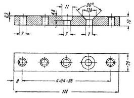
then the laser will not help you. However, I found that such holes are simply obtained at home with the help of a Dremel and a corresponding conical nozzle, something like this: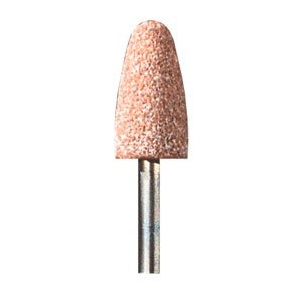
- Bilateral details. This refers to parts that can not be obtained without turning the sheet being milled - for example, having countersinking on both sides, or not through the grooves. Again, the laser disappears here. But with the milling is not so smooth. I do not know how in large firms, and where I milled, it would have resulted in ineffable hemorrhoids, would have increased costs in time, and, accordingly, in money. I believe that in large firms this will also not be free. So try to avoid such situations. You can countersink Dremel, it will be fast and free.
- The milling cutter has a non-zero radius. It is obvious. Therefore, it should be remembered that internal cuts can not be less than the radius of this cutter. That is, the inner corners will be rounded, which means that your parts inserted into these grooves will not fit in anymore. Let me explain with an example:
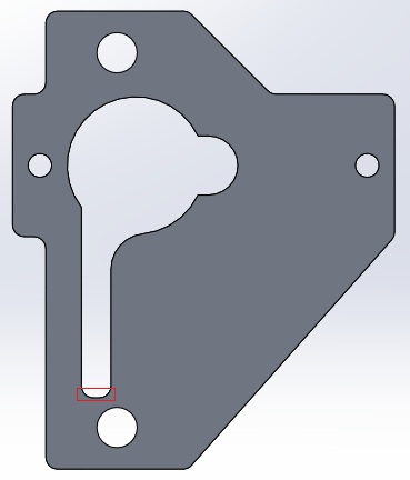
This is a detail of the servo mount, the knot from the base of the foot, where two servos are mounted. Red frame circled technological rounding. If it is not made in the model, the router still cuts through it - because physically can not make a right angle. But only to lengthen your groove, it, of course, will not, therefore its real length (that is, the length of the part with a constant width) will be less by the cutter radius. If you do not want to finish parts with a file, then it is better to foresee this moment right away. - Dimensions. You have to re-measure everything. You hear? All The first step is to purchase an electronic caliper (you can also use a regular one, but with an electronic one is more convenient), such as
and re-measure all purchased parts in your design with an accuracy of 0.1 mm. First, the sizes given on the Internet are often very inaccurate. And secondly, for the Chinese, it seems, there is no such thing as a normal drawing, in principle - for example, what they give to their servo drives:
More than half of the required size is missing, the rest do not correspond to the truth. Here with this I pinned very much. No, I measured everything that was necessary. But when I painted the above-mentioned detail, measuring the cylindrical protrusions on the drive (as you can see from the part, there are two of them, one big, the shaft sticks out of it, the second is smaller, stuck to the first), I decided without thinking that the small one lies on side of the big. After the test piece was cut out, the drive did not get into it. Upon a more detailed examination, it turned out that the small cylinder does not lie on the side of the large, but is displaced by 0.3 (!) Mm. These 0.3 mm was enough for the drive not to be squeezed in to the right place.
Of course, not everywhere dimensions are so critical - you need to look at the design, where the error does not greatly affect. But most importantly, do not forget about it and measure everything.
After I adjusted the construction several times, the shoals finally disappeared, and I received a package of my items, from which I began to assemble Ectognatus.
Assembly
At the assembly stage, there was no special rake. I will note only two things.
- Nuts unscrew. Mercilessly. Unfortunately, there were no grounding washers preventing self-loosening for M2 screws, and where there were M3, they stopped the bearing, so they had to be abandoned. And then, in the process of work, I had the opportunity to contemplate falling nuts on the go. Therefore, after the construction has been assembled and tested, you can put the nuts on the enamel or paint on the old frame, which I did. Self-unscrewing stopped, everyone is happy.
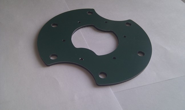
- Paint the robot. Since this very ALUKOBOND was not very pleasant color - blue on the one hand, green on the other, I decided to paint it. Black matt enamel was very, very good for this business. Goes well, dries instantly. True, I painted with a brush, and spray, as I was later told, the result is better. Not tested, but very possible.
This is what a freshly milled part looked like.
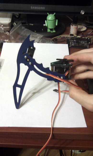
Leg assembly, design verification.
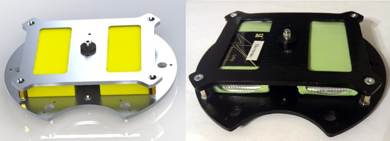
Model and real torso of the robot
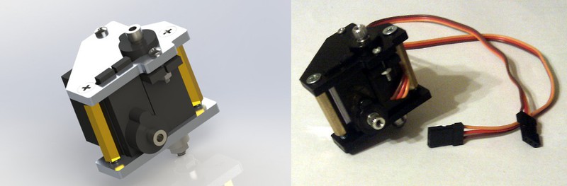
Model and real servo node
Ectognatus assembly
Check
So, after the whole structure has been assembled, it's time to check it in action.
Before designing custom electronics, I wanted to check how it behaves in the real world, current consumption, etc. For verification, it was decided to use the Mini-STM32 board, which I already mentioned in the corresponding article .
Since it is impossible to power electronics and drives from a battery without a converter, batteries have so far been left out of work, in construction, but unconnected.
For the test, I chose the following path: a switching board is made from the layout, to which all the drives are connected - the power and ground are separated into 18 drives, and their signal inputs are grouped into three pieces (one leg). Mini-STM32 connects to this board with wires with sockets ( like these ).
Since there were a lot of channels (18 pieces!) And the frequencies there were about 50 hertz, there was no point in chasing hardware SHIM, only to look for hemorrhoids. Therefore, the signal inputs from the drives I hung on the usual free GPIO. A radio module with a chip from Nordic was connected to the SPI controller, which I never cease to admire: http://www.ebay.com/itm/1pcs-NRF24L01-2-4GHz-Antenna-Wireless-Transceiver-Module-For-Microcontr-/ 261072511055
Since at one time I wrote a driver for FreeRTOS for it, working on interraps and DMA and not just a pollingue, I brought this FreeRTOS to the board.
In fact, it turned out to be a radio-controlled 18-channel PWM generator. From the point of view of the software, there are no special tricks, except for the driver for the radio module. PWM is generated using one timer, using the same method as in this article from DIHALT
There is an array of 18 structures
typedef struct { u32 __O *PinAddress; u16 DutyCycle; }PWMChannel; Where * PinAddress - bitband address management of the selected foot. The array is sorted in ascending order by the DutyCycle , the DutyCycle of the first element is entered into the Capture-Compare register, and in the interrupt by coincidence of the timer, the level of the corresponding pin is set through PinAdress . After that, the DutyCycle of the following is entered into the SS register. When the timer reaches the maximum, all the pins are set to 1, the array is re-sorted (in case new values arrive), and everything repeats. So that the received values do not knock down the generation, they are entered into the new Work array, and at the time the timer overflows, the Work and Sorted arrays are swapped — thus, we get double buffering.
To communicate with the computer using the same board, with the same radio module connected via USB. In it, I implemented a HID device, so the data is sent to it elementary, without additional drivers, from any convenient programming language. My control program, for example, on C #. Of course, the transmitter is controlled by FreeRTOS, in order not to have to rewrite the module driver. Information transfer to the robot goes in one task, data exchange with USB - in others. Even if nothing new came through USB, the transmitter constantly “pings” the robot, sending it a packet with the appropriate header. Since the aknolage of the radio modules is hardware, you can immediately find out if there is a connection with the robot or not, and set yourself the corresponding byte in status. USB task as a report sends exactly this status.
If new data arrived (angles for 18 drives, raw, no frills), then USB-task puts them in the queue for the transmission, and the transmitter-task in the same raw form sends them to the robot, which, on receipt, enters them in the already mentioned array Work.
Thus, all the logic can be implemented on a computer - only the duty ratio of the drives will be transferred to the robot.
Of course, in the future this will be implemented differently, but for testing it is the best way possible - it is not necessary to alter the glands a hundred times.
The prog program written in half a day cannot boast, of course, but in principle it performs its functions. So far, no IR, only forward kinematics for drawing models and trite forehead sequences for movements.
After everything described above was done, I recorded several sequences to Ectognatus, which he reproduced in this video:
The wires connected to it are powered by the LBP, for the reason of the absence of the converter already described above.
So, it's time to talk about the most important thing. All rakes rakes all shoals jamb.
Song of praise Chinese servos
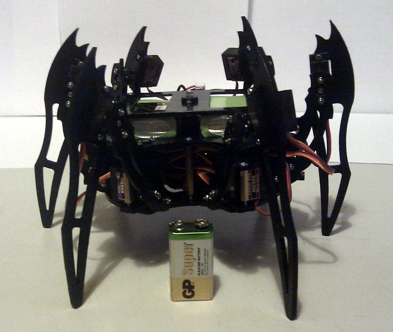
Do you know what the check showed? The robot barely stood. He could somehow keep his weight on six legs, but it was enough to lift two, and he fell on this side. Seen me very, very much upset. Hands straight down. I sat and thought, “did my rough calculations turn out to be so erroneous that the robot cannot hold on?”. I took it "floor" with batteries - instead of 650-700 grams Ectogatnus began to weigh 500-550. After that, he reluctantly portrayed his willingness to work - the video above was captured under these conditions. But how so? And then I thought - “maybe something is wrong with the drives?” And decided to measure the time declared by the manufacturer. It was here that the rake, which so painfully sounded on my forehead, came to light.
Like all the rakes, they consisted of two parts - the one on which you are attacking, a small metal one, and one that severely hits the forehead.
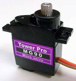
The metal part of the rake was the fact that manufacturers produce two types of drives, the MG90 and MG90S. They differ somewhat in parameters and design.
Here is the MG90S, the ones that I bought:
Weight: 13.4g
Dimension: 22.8 * 12.2 * 28.5mm
Stall torque: 1.8kg / cm (4.8V) - 2.2kg / cm (6.0V)
Operating speed: 0.10sec / 60degree (4.8v) - 0.08sec / 60degree (6.0V)
Operating voltage: 4.8-6.0V
But MG90:
Pay attention to the protrusion from the bottom of the drive (which I called “asshole”, because in this situation it was it, without getting up into the design). In the drawing it is perfectly visible:
But its parameters:
Weight: 14g
Dimension: 23.1 * 12.2 * 29.0mm
Stall torque: 2.2kg / cm (4.8V) - 2.5kg / cm (6.0V)
Operating speed: 0.11sec / 60degree (4.8v) - 0.10sec / 60degree (6.0V)
Operating voltage: 4.8-6.0V
Notice the difference? A little slower and a little stronger. Well, well, I stepped on this part of the rake myself - I had to take, of course, MG90, which are stronger. However, they didn’t get up to the design only if they tried to install both in the servo-mount (to tell the truth, not because of the “assholes” but because they were a little higher in height than the length, but designed for square drives). But with the MG90S, he got up in the mount like a glove, without any problems. This suited me perfectly, since the weak MG90S remained only as a turning serf, on which there was almost no load. A servos, which accounted for all the weight easily replaced by MG90.
And now we turn to the rake handle. Big and heavy. So, how do normal people perceive Stall Torque? Obviously, like this: “If Stall Torque is set to X * Y, then when we hang at a distance X from the axis of the servo a weight of less than Y, the server will be able to lift this load. If the mass is about Y, then the server will be able to hold it, but it will not be able to lift it anymore. ”
For expensive and good drives this is true - however, it still does not interfere with checking. But the Chinese comrades perceive this parameter differently. It is practically not connected with the real moment. I do not exaggerate, it means that for one MG90S the moment can be three times less than stated, for another - three and a half. For MG90 - two. Etc. That is, there is not even a linear relationship, you can not just "divide by three", let's say.
But let's detail. I decided to measure the moment of my drives. To do this, you can use a simple device - a container in which we will pour water, something that will serve as a shoulder and measuring cup. As a shoulder, I took the horizontal part of the leg of the robot, 6 cm long. Thus, I expected that the servant would be able to raise the capacity from 300 ml of water while feeding the pot 5B of the source. The moment in this case would be equal to 0.3 * 6 = 1.8 kg * cm. The container was a liter juice bag, from which I cut off the top and through which I passed a strong wire instead of a pen. If you repeat this at home, make sure that the bag itself and the handle hold tight, otherwise you can pour all the equipment. The shoulder is screwed to the servo drive, the package is hung on the second end of the shoulder, a small program gives the minimum value of the angle of rotation, which is replaced by the maximum when you press the button. In this case, the serv tries to raise the load from the lowest to the highest position. By the amount of water we determine the weight of the load, and hence the moment acting on the servu. The moment at which the server can no longer lift the load, but it will lift with a slight decrease and there will be a Stall Torque.
What I saw in the end: 300 ml (moment 1.8) - the server does not move. Well, the moment is overstated, it is expected. But in my opinion, I had a large supply, how much did they overstate it? We continue to measure.
250 ml (moment 1.5) - almost does not move.
150 ml (moment 0.9) - rises slightly, does not even reach the middle
100 ml (moment 0.6) - almost reaches the middle
~ 90 ml (time 0.54) - raises the load.
Honestly, I didn’t believe my eyes - I understand that it is possible to overstate the figures, but more than three times ... Maybe this is such a serv? But no, I measured all 20 pieces that I ordered.
As a result, two thirds behaved as described above, one third was even weaker (as far as I did not find out). In addition, there was a strong variation in PWM, that is, for one serf, the extreme rotation was at the duty cycle, say 0x200 (the value of the timer register), for the other - 0x1E5, and so on.
But it is not all that bad. I ordered 20 MG90 drives, those with an asshole and stronger. The results of the measurements were more rosy - at the stated moment 2.2 they gave out about 1.2.
That is, the characteristics were overestimated not only three, but only two times. Well, and still there were those that turned out to be weaker than the others, but still it was no longer so critical.
I remind you that MG90 is only 1.2 times stronger than MG90S by the parameters stated on the website, but in reality MG90 is more than twice as large as MG90S. In addition, they turned out to be noticeably quieter and less prone to oscillations around the setpoint - hi to the MGIDS PID regulator.
The conclusion from this is this: never believe the infe received from Chinese manufacturers, if you don’t want to later discover that the parameters on the site are related to real ones only through the phase of the moon and the astral twists. Before development, do not spare money for 1-2 drives, count its real time, consumption, speed. It will be cheaper than re-ordering the entire batch. Well, if you buy Chinese drives - take a reserve necessarily. It’s not only that a third turned out to be even weaker, but also that one was generally broken (it jerked terribly, apparently there was something wrong with its regulator), the pair burned down from the strain and another blew off the gear with motor shaft.
However, those that I purchased the second time, MG90, I am quite pleased. As a result, the robot rose quietly along with the batteries, absolutely calmly could lift its legs without fear of falling, and even could rise from the “unfolded” position (as on the video) in one motion, purely due to the strength of the servos, without propping up previously, with the tips of the legs.
Upcoming improvements
It was at this moment that I paused. Well, more precisely, I didn’t stop at all, but slowed down the pace of development, since my vacation ended and a lot of work began. Now I am in the process of designing custom electronics for a robot, about which I will say a few words in the article.
First of all, you need to design a serious enough converter that can deliver 30W to the drives. I found a very entertaining chip, which, according to International Rectifier's assurances, is capable of providing DC-DC conversion from 11.1V to 6V x 10A without a radiator, despite the fact that it does not need external mosfets - only a power choke.
Here it is, darling: http://www.irf.com/product-info/datasheets/data/ir3475m.pdf
10A drives, of course, will not pull - the maximum I saw when all drives are locked, and the robot is trying hard to get up - about 6A. So mikruhi should be enough. But this is in theory, in practice, I never used it - if someone worked with her, share your impressions.
I leave the calculator STMk, about the same as on the debug, and, in the distant future, I will push the inverse kinematics into it.
Initially, the connection was planned to be left on these radio modules - they are convenient, I have already written firewood for them, there is a version that is fully compatible with pins, but with an heaving amp, which is half a kilometer away. And I planned to put the camera on the roof of the robot. Of course, in order not to do useless work on getting a “raw” signal from the camera, and sending it over this module (which does not have enough speed to send normal video), I planned to take a camera with a built-in transmitter, for example, such .
On the other side, a rather dimensional receiver is placed, and since the output from it is analog, a usb device is added here that allows you to connect analog video sources to your computer. And, in principle, I have already come to terms with this, but then I saw him .
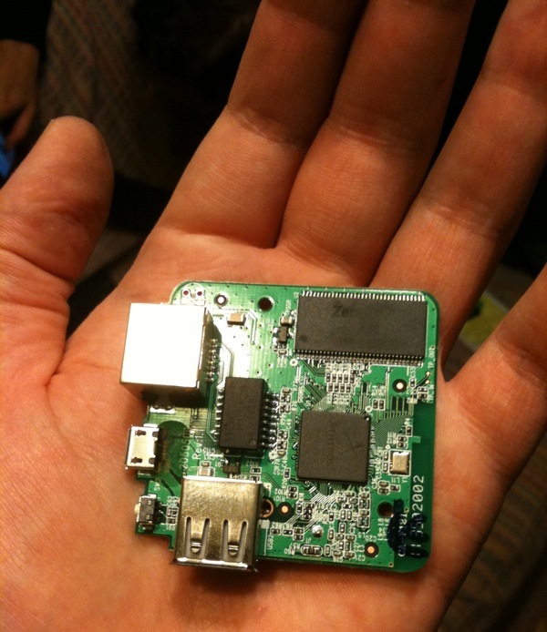
Router TL-MR3020. Miracle of Chinese technology for 800 rubles. Outwardly very similar to the Apple device.
Internally - a full-fledged comp with Linux, which has long been ported to OpenWRT.
The board inside it is only 5.7x5.7 cm. And it has a USB host!
Its consumption, even with the harshest transmission, does not exceed 180 mA, and the average is about 100.
As it turned out, this router (and its full analogue, just intended for the domestic Chinese market, TL-WR703N, about which most articles are written, if you search, search by this title) has long been used by electronic engineers as a single board computer, which can be used in their handicrafts. It easily and naturally rises normal video streaming, you can easily connect it to a regular webcam.
More similar about TL-MR3020 and his twin brother TL-WR703N can be read on the website OpenWRT
At work, I am picking it up just now, so I had the good fortune to work with him live.
So now my plan is this - on my board there is a converter that provides power to all the nodes of the circuit, STMka, which acts as a controller for all mechanics (legs and pivotal serva on the roof, turning the camera), and, perhaps, a couple of sensors — say, an accelerometer, to watch your tilt. On this board, a board from TL-MR3020 is placed on top, with OpenWRT on board, which provides streaming video and the connection of the robot with a computer via Wi-Fi. Previously, extra connectors are removed from it, of course - there is nothing to occupy space. It will also be connected to my board via USB, the board with the controller of the legs will be introduced by a HID device. Thus, we get rid of the bulky analog video receiver, the converter that comes with it, the separate transceiver module to the computer, and we are able to steer the robot from any device with Wi-Fi, while simultaneously watching through its camera, for example - from an iPad.
I have everything on this for now, as soon as there is time and I’m completing the fees and getting results, wait for the next article.
Thanks for attention!
Source: https://habr.com/ru/post/149038/
All Articles