We do it yourself Single-Side Arduino with a COM port on board
Being engaged in electronics and microcontrollers, I am well aware that it would be nice to have a ready-made debug board on hand. With its help, you can quickly check any servo drive, sensor, etc., or even build on it the whole project. That is why I decided to make Arduino myself.
The creators of the famous platform took care of DIY amateurs and prepared a special one-sided version of the board for this. Also on the Internet there are very detailed instructions on how to make it at home . Unfortunately, this board has several drawbacks, namely: connecting only through the COM port and powered exclusively from the adapter. I decided to eliminate it and in the end I got this nice fee:

')
Of course, the idea is not new, and on the Internet, the idea of screwing a virtual COM port to the Single-Side Board sounded more than once, but I have never met a finished project.
Anyone who ever dreamed of making an Arduino for themselves, I ask for a cat.
In the original board, I replaced the COM port with an FT232RL IC. It works with the logic levels of TTL, so the converter (which in the original arduine is made on transistors) is not needed. To select the power source in the diagram provides a three-pin pinheder. It allows you to specify the position of the jumper power source: USB-port (the position of "int") or power supply connector (position of the "ext"). FTRL'k always eats only from USB. There is also a jumper "auto reset enable". Basically, I am doing responsible projects in P-CAD. Exporting graphics in it is quite complicated, so I post only screenshots of the drawings.

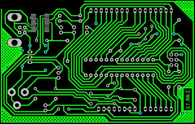
The board is almost completely stripped from the original, except for the FTRL's connection, the look through:
as well as an assembly drawing:

I recommend to put capacitors C7, C8 on its side so that they do not protrude above the connector.
About how to solder something on your own, DI HALT wrote the best and most of all. I will only add that problems can arise with FTRLs. I tried on the pickled board to tin the pads under it - I almost tore it off. So I recommend to solder the findings one by one. By the way, it is advisable to clean the flux board: twice I saw such that, after soldering, the unwashed mikruha was not detected by the computer. If desired, the same LUT'om put on the front side of the board assembly drawing, but then it can not be washed in the bath with acetone.
When the board is made, you can do the software. First of all, you need to download and install Arduinov’s IDE’s . as well as the driver for the FT232RL chip.
Now you need to flash the bootloader. Personally, I use this programmer for firmware, do not consider it an advertisement. More details about the bootloader firmware can be found here . The firmware file itself lies on the hard disk at: C: \ Program Files \ arduino-1.0.1 \ hardware \ arduino \ bootloaders \ atmega8 \ ATmegaBOOT.hex. I just installed the controller in a ZIF socket and directly patched this file. I took the fusion beats from here . It should be noted that I tried to run this board with the 168th mega, but I still could not do it. Most likely, no bootloader came up.
Programming arduino is easy. Start the programming environment and select the board (in our case, this is Arduino NG or older w / ATmega8):

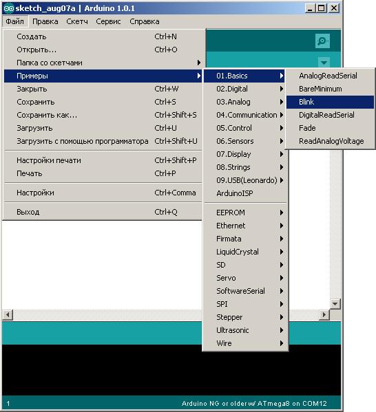
Then we run a ready-made example that blinks a custom LED:
Next, click File-> Download and watch:
If everything is assembled correctly, it works immediately. I found an error when downloading - the output of Rx FTRL was badly soldered, but I quickly corrected it.
In the archive you can take all the drawings, firmware, as well as a list of parts for purchase. The drawings are made in CAD P-CAD 2006. If someone helps prepare the files for LUT, I will be very grateful.
This board is fully arduino-compatible and allows working with standard shields and IDE's, although I myself rarely use them. In my opinion it is easier to assemble a project in AVR-studio - in the old fashioned way))).
UPD:
The main article is now stored here .
The creators of the famous platform took care of DIY amateurs and prepared a special one-sided version of the board for this. Also on the Internet there are very detailed instructions on how to make it at home . Unfortunately, this board has several drawbacks, namely: connecting only through the COM port and powered exclusively from the adapter. I decided to eliminate it and in the end I got this nice fee:
')
Of course, the idea is not new, and on the Internet, the idea of screwing a virtual COM port to the Single-Side Board sounded more than once, but I have never met a finished project.
Anyone who ever dreamed of making an Arduino for themselves, I ask for a cat.
In the original board, I replaced the COM port with an FT232RL IC. It works with the logic levels of TTL, so the converter (which in the original arduine is made on transistors) is not needed. To select the power source in the diagram provides a three-pin pinheder. It allows you to specify the position of the jumper power source: USB-port (the position of "int") or power supply connector (position of the "ext"). FTRL'k always eats only from USB. There is also a jumper "auto reset enable". Basically, I am doing responsible projects in P-CAD. Exporting graphics in it is quite complicated, so I post only screenshots of the drawings.
The board is almost completely stripped from the original, except for the FTRL's connection, the look through:
as well as an assembly drawing:
I recommend to put capacitors C7, C8 on its side so that they do not protrude above the connector.
About how to solder something on your own, DI HALT wrote the best and most of all. I will only add that problems can arise with FTRLs. I tried on the pickled board to tin the pads under it - I almost tore it off. So I recommend to solder the findings one by one. By the way, it is advisable to clean the flux board: twice I saw such that, after soldering, the unwashed mikruha was not detected by the computer. If desired, the same LUT'om put on the front side of the board assembly drawing, but then it can not be washed in the bath with acetone.
When the board is made, you can do the software. First of all, you need to download and install Arduinov’s IDE’s . as well as the driver for the FT232RL chip.
Now you need to flash the bootloader. Personally, I use this programmer for firmware, do not consider it an advertisement. More details about the bootloader firmware can be found here . The firmware file itself lies on the hard disk at: C: \ Program Files \ arduino-1.0.1 \ hardware \ arduino \ bootloaders \ atmega8 \ ATmegaBOOT.hex. I just installed the controller in a ZIF socket and directly patched this file. I took the fusion beats from here . It should be noted that I tried to run this board with the 168th mega, but I still could not do it. Most likely, no bootloader came up.
Programming arduino is easy. Start the programming environment and select the board (in our case, this is Arduino NG or older w / ATmega8):
Then we run a ready-made example that blinks a custom LED:
Next, click File-> Download and watch:
If everything is assembled correctly, it works immediately. I found an error when downloading - the output of Rx FTRL was badly soldered, but I quickly corrected it.
In the archive you can take all the drawings, firmware, as well as a list of parts for purchase. The drawings are made in CAD P-CAD 2006. If someone helps prepare the files for LUT, I will be very grateful.
This board is fully arduino-compatible and allows working with standard shields and IDE's, although I myself rarely use them. In my opinion it is easier to assemble a project in AVR-studio - in the old fashioned way))).
UPD:
The main article is now stored here .
Source: https://habr.com/ru/post/149006/
All Articles