Overview of the laboratory power supply Mastech 3003D
Preface.
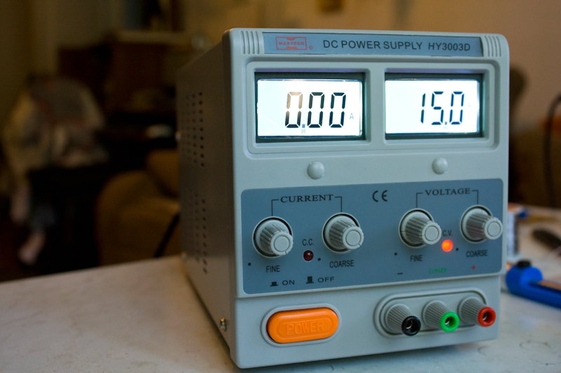
Greetings to the community. This short article will provide an overview of the Mastech laboratory power supply. I will not discuss the choice of model, but I hope that this article will help other electronics lovers to make their choice.
Contents of delivery
Everything is as usual: cardboard box, polyethylene, foam.
The package includes the unit itself, the power cord and the four-page user manual in English.
There are 3 large series of power supply units for Mastech: with an arrow indication, with an indication on seven-segment LED indicators and with LCD displays. Differences between similar products of different series on this end.
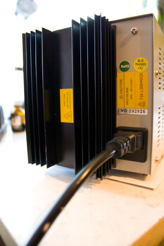
What's inside?
The appearance of the device inspires confidence: nothing creaks, no backlash, potentiometers are not turned. Already well, now take a look inside.
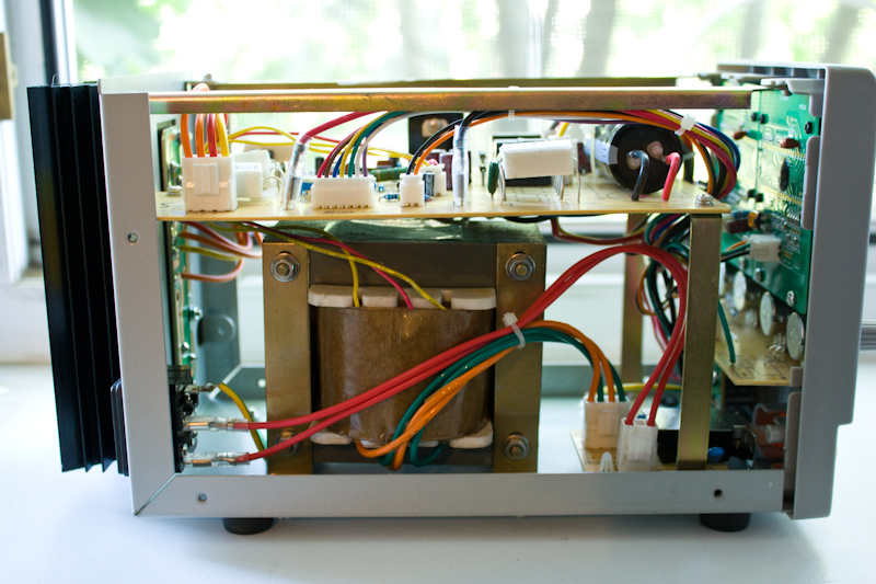
The heart of the power supply is a weighty transformer, which occupies most of the volume and mass of the PSU. Manufacturers did not stint copper.
')
On top of the actual board stabilizer.
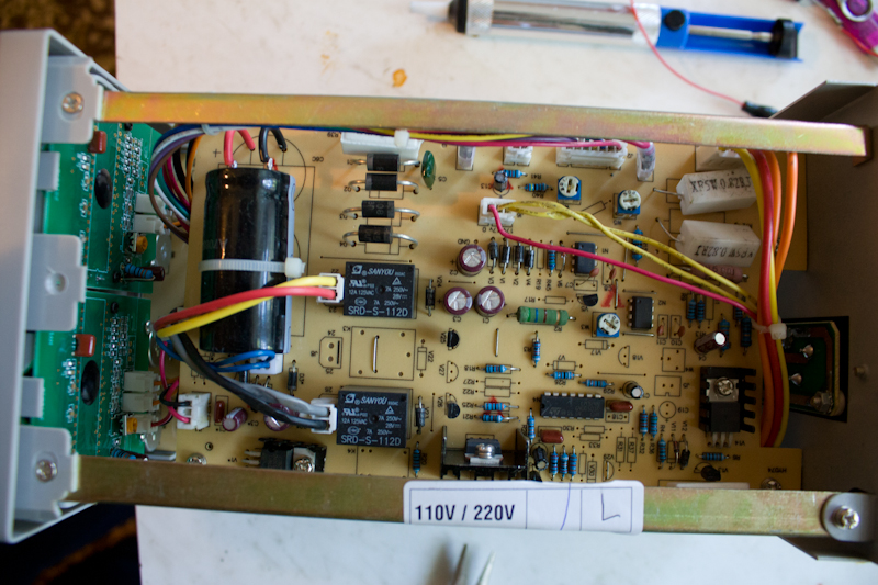
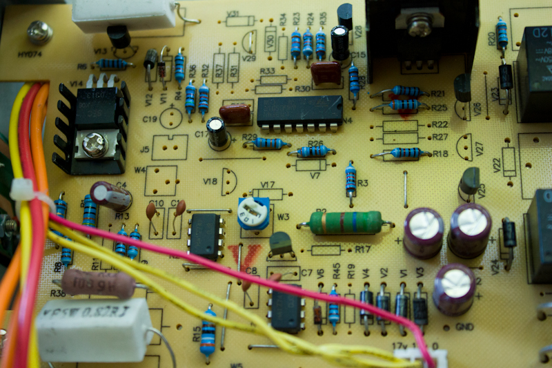
Build quality is good, the only thing - powerful wire resistors are not all neatly mounted.

The widely used 2N3055 are used as control transistors. As many as 2 pieces, although our power supply has a maximum current of 3A, and each of the transistors can provide a current of up to 15A. Good stock however.
Voltage regulation occurs with the switching of the secondary windings. Those. at low installed voltages, low-voltage windings are switched, with increasing, higher-voltage windings. Switching occurs at the following voltages: 7.5V, 15V and 22V. Switching occurs without voltage spikes. This structure helps to reduce the amount of heat generated by control transistors. The filter capacitor costs 4700 microfarads * 63V, which may seem insufficient for some, but as we will see later, its capacity is quite sufficient. Outputs are equipped with screw terminals, allowing even connect the type of "banana".

The transistors are isolated from the case and covered with a metal plate:
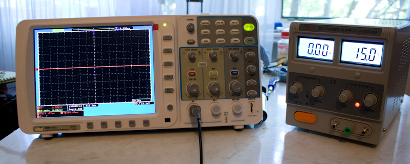
Measurements
For a more or less adequate assessment of the characteristics of the product, it was decided to carry out 3 small tests: work at idle, work under load, work in current limiting mode. All measurements were carried out using an oscilloscope in the closed input mode.
This mode of operation is needed to cut off the input of the constant component so that you can clearly see the pulsations.
The first test should show the amount of noise at the output of the PSU at different voltages; the second - whether there are any artifacts when working on the load; the third is how well the current limit works (again, does the voltage form turn into a saw, etc.)
Idling.
Oscillograms are shown at idle with different output voltages.
2B: 1 mV ripple.
10V: 0.7 mV ripple
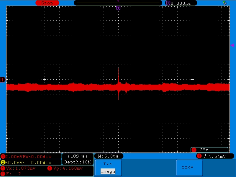
15B (made with a different horizontal scan value). Pulsations of 0.8-1 mV.
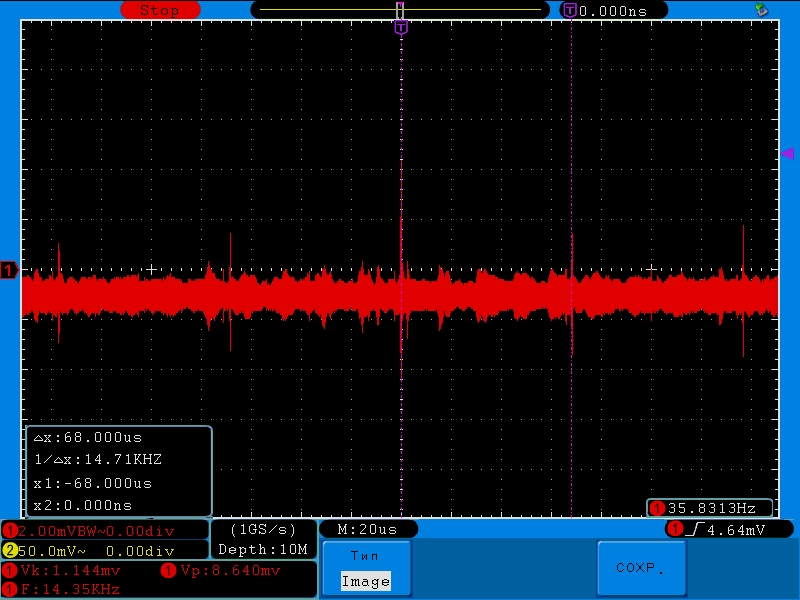
50 µs / div:

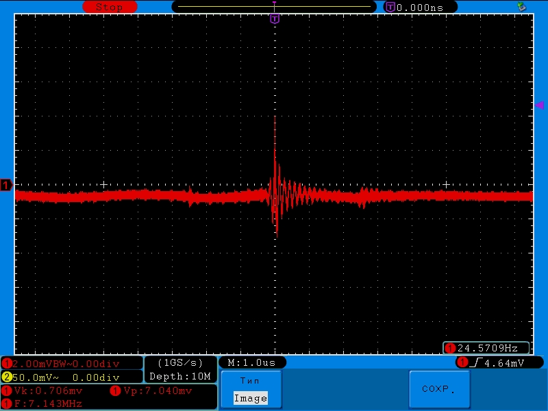
Here you can see periodic emissions with a small amplitude. Using cursors, reducing the scale to 20 μS / div, you can measure the frequency: it turns out about 14 kHz:
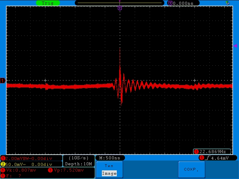
And the final snapshot with a scale of 500 ns / div:
20V: 0.4 mV ripple

and 30B: 0.45mV ripple

Under load
A wire resistor with a nominal value of 20 ohms and a power of 5 W of domestic production C5-5V acts as a load. However, during the experiments, the power dissipated on it was four times higher than the nominal power, and nothing happened to it.
Voltage 20v, current 1A:


As you can see, no artifacts appeared, only the level of pulsations increased slightly.
Current 3A, as a load - 3 parallel-connected resistors of 20 Ohm * 5W.

Pulsations <1mV.
Current limiting mode
Now let's try to limit the current by half - up to 500 mA:
And again, everything is quite predictable.
Of course, in the power supply there is a protection against a short circuit at the output, which was “lucky” to test several times (by connecting the device in the wrong polarity). The protection worked very quickly.
The manufacturer declared the following characteristics:
| Parameter | Value |
|---|---|
| output voltage, V | 0-30 |
| output current, A | 0-3 |
| current ripple level, mA | <= 3 |
| voltage ripple level, mV | <= 0.5 |
| load factor,% current | <0.2 + 5mA |
| load effect coefficient,% by voltage | <0.01 + 5mV |
| coefficient of influence of supply voltage,% current | <0.2 + 1mV |
| coefficient of influence of supply voltage,% voltage | <0.01 + 1mV |
| Display of output current and voltage | 3 1/2-digit LCD indicators |
| Overall dimensions, mm | 206 x 153 x 110 |
| food, In | ~ 220V ± 10% |
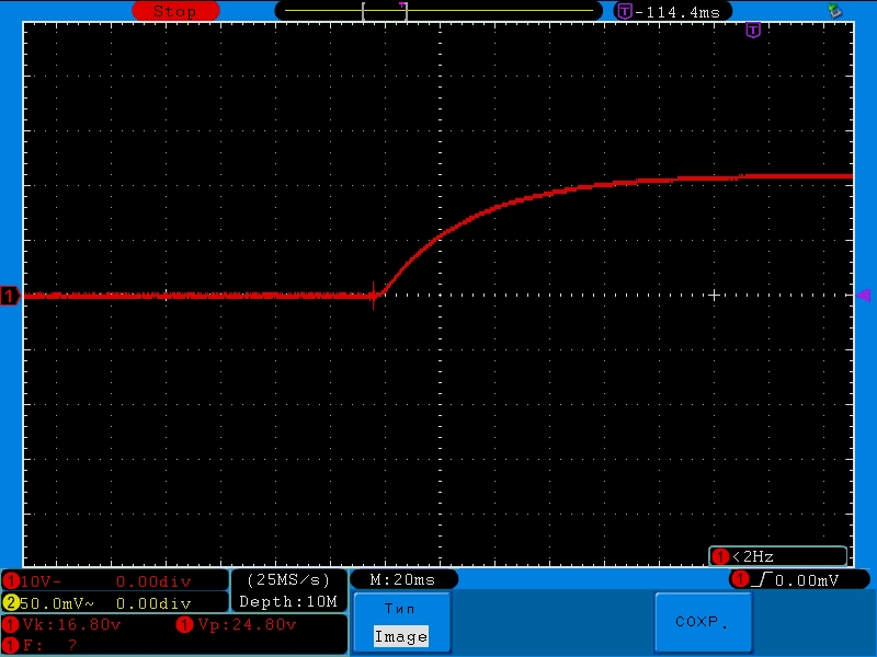
I will also give an oscillogram of the transient response during switching on.
At the request of the community made waveforms connect and disconnect the load.
Connection:


Disable:


Verdict
Although the pulsations turned out to be somewhat higher than the declared, but still have a fairly low level. Such characteristics are enough to configure and debug most radio amateur designs. Of course, the whole raspberry was somewhat spoiled by the transient characteristics when connecting / disconnecting the load.
Source: https://habr.com/ru/post/148678/
All Articles