Control of several servos with high accuracy on ATmega16 MK
Recently, I was approached by acquaintances from a mock-up workshop and offered to work on a very interesting project. They needed to carry out a model in which the details of several machines (a crane, an excavator, a destroyer) would move. The logic is simple, but the peculiarity is that they had to move at a speed that is much lower than the speed of the drives themselves, and this can only be done by passing through intermediate points. In this article I want to introduce you to an interesting method of precise control of a large number of servos.
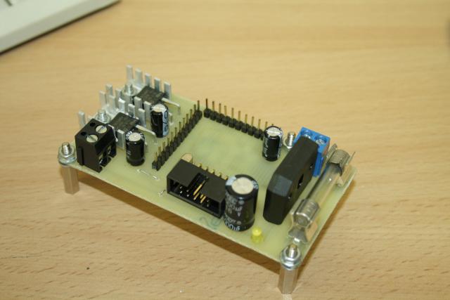
In my case it was supposed to use four drives. For this project, I made a small fee:
')
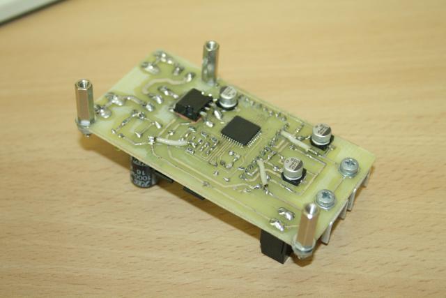
The board itself is simple - an Atmega16A-AU microcontroller, a stabilizer for the controller, two stabilizers on the drives, and a PLS connector for connecting the drives. In my case, there was almost no load on the drives (servos moved with paper parts), so for the drives there was enough of a linear stabilizer on a small radiator.
In drive management, I found the two most interesting articles in alex-exe and di halt . But in both methods there are certain disadvantages. In the first case: it is necessary to cause an interruption too often, which slows down the fulfillment of the main loop hardly predictable and does not allow to obtain high positioning accuracy. In its implementation, the drive jerks quite strongly, the installation accuracy is about 1 degree. Actually, here is the video:
The DI HALT method assumes the formation in ascending order, that is, it is necessary to additionally calculate signals.
In this regard, I want to propose another method that avoids both these difficulties.
The principle of servo control is simple: it is necessary to send pulses with a duration of 0.8–2.3 ms with a period of 15–20 ms. The pulse duration determines the position of the servo drive. The proposed method involves the formation of pulses on the legs MK one by one, as shown in the figure.
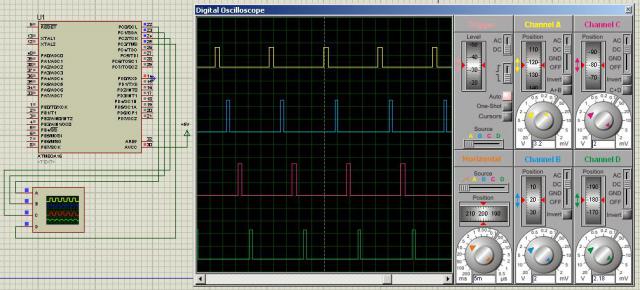
To implement this method, only one timer is sufficient. I set the timer to increase every microsecond. The entire signal period is 18000 μs, the time for the formation of a single pulse is 4500 μs. A timer interrupt when running four servos is called eight times. Hence the limitation of the method: it will not work for one timer to hang more than 8 drives (in 20 ms, you can form a maximum of 8 pulses with a duration of 2.3 ms).
Variables angle1-angle4 are angles in normalized units, varying in the main program loop. To change the angle from 0 to 180 degrees, they must change from 800 to 2200. All control takes place in the interrupt handler. When the timer is first triggered, the leg responsible for the first drive is set to one. The value of the angle for this drive is also recorded in the OCR1A register. The next time the leg is triggered, the leg is set to 0 and the number of ticks that is left until the end of the control period for one drive is recorded in the OCR1A register (I have 4500). Then the same thing is done with the foot responsible for the second drive. Thus, every 4.5 ms on one foot after another, an impulse of the required duration appears, and with an accuracy of up to 1 μs! That is, the accuracy of the angle setting will be less than 10 minutes and is limited by the characteristics of the drive itself. So, the code itself:
I will not give the text of the whole program, I will just say that the corners in the main loop can be formed in any way - at least according to data from the UART, even from the ADC. I actually scored with my hands where to go, where and how much to stand, etc. I also had a toggle switch. In the on position, the servos move according to the program, and when they turn off, they return to their original position. If necessary, all the source code of the project can send to the mail.
Here is a video of the four drives:
Pay attention to the drive in the lower left corner - the movement is almost negligible! This drive controls the boom of the crane. I will add more about the drives themselves. I got four different drives in my hands - two analog and two digital ones. It is noteworthy that both analog drives could work normally only for a couple of minutes, and then start arbitrarily twitching, clamping in extreme positions, etc., although both drives were working - I checked it with a servo tester. Digital drives performed everything clearly and stably for several hours in a row (and maybe a day). I did not hear any complaints from the customer. For the boom crane, I used the Hi-Tech drive, which changed its position with minimal steps.
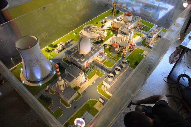
And finally - a photo of the layout. Video, unfortunately, I can not post.
UPD:
The main article is now stored here .
In my case it was supposed to use four drives. For this project, I made a small fee:
')
The board itself is simple - an Atmega16A-AU microcontroller, a stabilizer for the controller, two stabilizers on the drives, and a PLS connector for connecting the drives. In my case, there was almost no load on the drives (servos moved with paper parts), so for the drives there was enough of a linear stabilizer on a small radiator.
In drive management, I found the two most interesting articles in alex-exe and di halt . But in both methods there are certain disadvantages. In the first case: it is necessary to cause an interruption too often, which slows down the fulfillment of the main loop hardly predictable and does not allow to obtain high positioning accuracy. In its implementation, the drive jerks quite strongly, the installation accuracy is about 1 degree. Actually, here is the video:
The DI HALT method assumes the formation in ascending order, that is, it is necessary to additionally calculate signals.
In this regard, I want to propose another method that avoids both these difficulties.
The principle of servo control is simple: it is necessary to send pulses with a duration of 0.8–2.3 ms with a period of 15–20 ms. The pulse duration determines the position of the servo drive. The proposed method involves the formation of pulses on the legs MK one by one, as shown in the figure.
To implement this method, only one timer is sufficient. I set the timer to increase every microsecond. The entire signal period is 18000 μs, the time for the formation of a single pulse is 4500 μs. A timer interrupt when running four servos is called eight times. Hence the limitation of the method: it will not work for one timer to hang more than 8 drives (in 20 ms, you can form a maximum of 8 pulses with a duration of 2.3 ms).
Variables angle1-angle4 are angles in normalized units, varying in the main program loop. To change the angle from 0 to 180 degrees, they must change from 800 to 2200. All control takes place in the interrupt handler. When the timer is first triggered, the leg responsible for the first drive is set to one. The value of the angle for this drive is also recorded in the OCR1A register. The next time the leg is triggered, the leg is set to 0 and the number of ticks that is left until the end of the control period for one drive is recorded in the OCR1A register (I have 4500). Then the same thing is done with the foot responsible for the second drive. Thus, every 4.5 ms on one foot after another, an impulse of the required duration appears, and with an accuracy of up to 1 μs! That is, the accuracy of the angle setting will be less than 10 minutes and is limited by the characteristics of the drive itself. So, the code itself:
ISR(TIMER1_COMPA_vect) { if (takt == 0) { PORTC |= 0b00000001; OCR1A = angle1; } if (takt == 1) { PORTC = PORTC & 0b11111110; OCR1A = cycle - angle1; } if (takt == 2) { PORTC |= 0b00000010; OCR1A = angle2; } if (takt == 3) { PORTC = PORTC & 0b11111101; OCR1A = cycle - angle2; } if (takt == 4) { PORTC |= 0b00000100; OCR1A = angle3; } if (takt == 5) { PORTC = PORTC & 0b11111011; OCR1A = cycle - angle3; } if (takt == 6) { PORTC |= 0b00001000; OCR1A = angle4; } if (takt == 7) { PORTC = PORTC & 0b11110111; OCR1A = cycle - angle4; } takt = takt + 1; if (takt == 9) takt = 0; } I will not give the text of the whole program, I will just say that the corners in the main loop can be formed in any way - at least according to data from the UART, even from the ADC. I actually scored with my hands where to go, where and how much to stand, etc. I also had a toggle switch. In the on position, the servos move according to the program, and when they turn off, they return to their original position. If necessary, all the source code of the project can send to the mail.
Here is a video of the four drives:
Pay attention to the drive in the lower left corner - the movement is almost negligible! This drive controls the boom of the crane. I will add more about the drives themselves. I got four different drives in my hands - two analog and two digital ones. It is noteworthy that both analog drives could work normally only for a couple of minutes, and then start arbitrarily twitching, clamping in extreme positions, etc., although both drives were working - I checked it with a servo tester. Digital drives performed everything clearly and stably for several hours in a row (and maybe a day). I did not hear any complaints from the customer. For the boom crane, I used the Hi-Tech drive, which changed its position with minimal steps.
And finally - a photo of the layout. Video, unfortunately, I can not post.
UPD:
The main article is now stored here .
Source: https://habr.com/ru/post/147940/
All Articles