We connect joysticks from Dendy to PC via Arduino
I think many of you remember those glorious times when we spent hours in tanchiki, ninja turtles, battletods and doubledragon and a couple of dozen other super games on the Dandy. It was a great time! Most of the games were damn complex, but even so, failure after failure, we still went to our goal and started the game again, so that we could go through to the end today.
Having ponostalled myself, I decided that I really want to play Dendy and want to play on the laptop, but not on the keyboard, but on the good old joystick.
Below I will describe what problems I encountered and how I solved them.
I will explain a little why this is how I wanted to play. The prefix I have survived and it works fine, but only a couple of cartridges remained (I distributed the rest to my friends). And playing the keyboard in the game dandy, well, it's somehow not ice at all.
')
There was a problem how to connect the joystick from the Dandy to the laptop.
A little googling, I realized that this is mainly solved by connecting through the LPT port and using ready-made drivers, but I have a laptop, and this does not suit me. Then I remembered that I have an Arduino Uno board and I decided that I would go my own way and use it.
The first problem turned out to be that the joysticks' connectors are internal, and all the pinouts found on the Internet were for external connectors.

I did not manage to find the specification for my noname dandy, so I began to look at the internal board to find power and ground, and to understand which of the five contacts on the joystick are connected to them. I dealt with it quickly. It turned out to be two extreme contact.
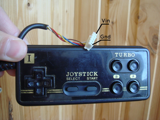
To Arduino, I connected everything directly, power - power 5V, earth - earth, the other three contacts connected to 2, 3 and 4 digital pin.
It turned out not so easy to find this information. Just a few posts on a couple of forums. Personally, this post helped me: code.google.com/p/avrtoys/wiki/joystick , namely this code: avrtoys.googlecode.com/svn/trunk/joystick/main.c . And here is the link to the article in Radio journal mentioned in this entry: ftp.radio.ru/pub/arhiv/1996/06-96/46-6-1996.gif . From all this, I concluded that I had to send a signal to Latch, and then 8 times to give a signal to Clock and read the value from Data every time, which after each Clock will contain information about the next button of the joystick.
If you are already set up or you are satisfied with the Arduino IDE, you can go to step 3.
I don’t know how you are, but personally the official Arduino IDE terribly depresses me, so I’ll briefly tell you how to use your favorite IDE.
First of all, I downloaded the source code for the Arduino IDE and found the code responsible for compiling and uploading the firmware there. Having spent a little time, I selected all the commands that are used there:
In the above command, when linking, the library libArduino.a is used, it can be obtained by compiling all * .c and * .cpp files from the folder with headers and collecting all the objects in one archive. And you can just run the Arduino IDE, compile any project and copy the file /tmp/build*.tmp/core.a. It will be absolutely equivalent.
All these commands are relevant for Arduino Uno, for other arduins, some parameters should be changed.
Now using these commands you can easily configure your IDE to automatically compile and download the firmware.
Here it was necessary only to determine which of the 2, 3 and 4 pins are responsible for Latch, Clock and Data. This I decided by trial and error. We assume that 4 is Data, and we do Serial.println (digitalRead (4)), if at the touch of a button there is some kind of reaction, then this is it. The remaining 2 contacts were determined when the firmware was already written, if everything works, then they guessed it, no - we swap them.
The code, again, was written on the basis of avrtoys.googlecode.com/svn/trunk/joystick/main.c :
As a result, I received 1 byte containing information about all 8 buttons of the joystick, about each in the corresponding bit. I got the following location: A, B, Select, Start, Up, Down, Left, Right. After this byte is sent to the computer, where it is received and processed by my "driver".
It is easy to see that you can easily connect a second joystick.
Here it was necessary to take this byte from the Arduino and emulate keystrokes. Yes, yes, pressing the joystick will be treated as pressing on the keyboard, good or bad.
As a programming language, I chose Python. Simple and effective, I believe, it was perfect for this task.
The only problem that arose here is the bounce of the joystick contacts . I solved it by introducing a time interval that occurs after changing the button state, during which the state does not change. Enough 0.05 s.
To emulate keyboard clicks, I used the xte utility that comes with Xautomation. It is very easy to use, here is an example:
To exit the driver, I used the state when the entire crossbar was fully pressed. This state corresponds to the number 0xf0.
Everything! It remains only to configure the dandy emulator, I chose FCEUX.
Specify in the settings those keys that are specified in the driver iiii remember childhood!
In fact, there are other, perhaps more effective ways to use Arduino in this situation. For example, if you have an Arduino Leonardo, you can use the Keyboard object to directly send keyboard commands to a computer. It is also possible, as I understand it, to reflash Arduino so that it appears as a joystick / keyboard / mouse and also directly send commands. Here is the tutorial: http://mitchtech.net/arduino-usb-hid-keyboard/ . However, my way completely suits me and I am more than satisfied with the result.
Like it or not, Arduino is a great platform for such experiments.
Now it remains only to collect all this as a separate device.
Well, and finally the video:
Having ponostalled myself, I decided that I really want to play Dendy and want to play on the laptop, but not on the keyboard, but on the good old joystick.
Below I will describe what problems I encountered and how I solved them.
I will explain a little why this is how I wanted to play. The prefix I have survived and it works fine, but only a couple of cartridges remained (I distributed the rest to my friends). And playing the keyboard in the game dandy, well, it's somehow not ice at all.
')
There was a problem how to connect the joystick from the Dandy to the laptop.
A little googling, I realized that this is mainly solved by connecting through the LPT port and using ready-made drivers, but I have a laptop, and this does not suit me. Then I remembered that I have an Arduino Uno board and I decided that I would go my own way and use it.
0. Definition of pinouts on the joystick
The first problem turned out to be that the joysticks' connectors are internal, and all the pinouts found on the Internet were for external connectors.
I did not manage to find the specification for my noname dandy, so I began to look at the internal board to find power and ground, and to understand which of the five contacts on the joystick are connected to them. I dealt with it quickly. It turned out to be two extreme contact.
To Arduino, I connected everything directly, power - power 5V, earth - earth, the other three contacts connected to 2, 3 and 4 digital pin.
1. Description of the joystick operation protocol
It turned out not so easy to find this information. Just a few posts on a couple of forums. Personally, this post helped me: code.google.com/p/avrtoys/wiki/joystick , namely this code: avrtoys.googlecode.com/svn/trunk/joystick/main.c . And here is the link to the article in Radio journal mentioned in this entry: ftp.radio.ru/pub/arhiv/1996/06-96/46-6-1996.gif . From all this, I concluded that I had to send a signal to Latch, and then 8 times to give a signal to Clock and read the value from Data every time, which after each Clock will contain information about the next button of the joystick.
2. Setting up the environment
If you are already set up or you are satisfied with the Arduino IDE, you can go to step 3.
I don’t know how you are, but personally the official Arduino IDE terribly depresses me, so I’ll briefly tell you how to use your favorite IDE.
First of all, I downloaded the source code for the Arduino IDE and found the code responsible for compiling and uploading the firmware there. Having spent a little time, I selected all the commands that are used there:
#!/bin/bash avr-gcc -c -g -Os -fno-exceptions -ffunction-sections -fdata-sections -mmcu=atmega328p -DF_CPU=16000000UL -I /usr/share/arduino/hardware/arduino/cores/arduino -I /usr/share/arduino/hardware/arduino/variants/standard $filename.cpp -o $filename.o avr-gcc -Os -Wl,--gc-sections -mmcu=atmega328p -o $filename.elf $filename.o libArduino.a -lm avr-objcopy -O ihex -R .eeprom $filename.elf $filename.elf.hex avrdude -V -p m328p -b 115200 -c arduino -P /dev/ttyACM0 -U flash:w:$filename.elf.hex In the above command, when linking, the library libArduino.a is used, it can be obtained by compiling all * .c and * .cpp files from the folder with headers and collecting all the objects in one archive. And you can just run the Arduino IDE, compile any project and copy the file /tmp/build*.tmp/core.a. It will be absolutely equivalent.
All these commands are relevant for Arduino Uno, for other arduins, some parameters should be changed.
Now using these commands you can easily configure your IDE to automatically compile and download the firmware.
3. Writing the firmware code
Here it was necessary only to determine which of the 2, 3 and 4 pins are responsible for Latch, Clock and Data. This I decided by trial and error. We assume that 4 is Data, and we do Serial.println (digitalRead (4)), if at the touch of a button there is some kind of reaction, then this is it. The remaining 2 contacts were determined when the firmware was already written, if everything works, then they guessed it, no - we swap them.
The code, again, was written on the basis of avrtoys.googlecode.com/svn/trunk/joystick/main.c :
Firmware code
#include <Arduino.h> const int data = 2; const int latch = 3; const int clock = 4; const int TICK = 2; void init_joystick(int data, int latch, int clock) { pinMode(data, INPUT); pinMode(clock, OUTPUT); pinMode(latch, OUTPUT); digitalWrite(clock, HIGH); } int get_keys_state_joystick(int data, int latch, int clock) { digitalWrite(latch, HIGH); delayMicroseconds(TICK); digitalWrite(latch, LOW); int keys_state = 0; for (int i = 0; i < 8; ++i) { delayMicroseconds(TICK); digitalWrite(clock, LOW); keys_state <<= 1; keys_state += digitalRead(data); delayMicroseconds(TICK); digitalWrite(clock, HIGH); } return keys_state; } void setup() { init_joystick(data, latch, clock); Serial.begin(57600); } void loop() { Serial.write(get_keys_state_joystick(data, latch, clock)); } As a result, I received 1 byte containing information about all 8 buttons of the joystick, about each in the corresponding bit. I got the following location: A, B, Select, Start, Up, Down, Left, Right. After this byte is sent to the computer, where it is received and processed by my "driver".
It is easy to see that you can easily connect a second joystick.
4. Writing "driver"
Here it was necessary to take this byte from the Arduino and emulate keystrokes. Yes, yes, pressing the joystick will be treated as pressing on the keyboard, good or bad.
As a programming language, I chose Python. Simple and effective, I believe, it was perfect for this task.
The only problem that arose here is the bounce of the joystick contacts . I solved it by introducing a time interval that occurs after changing the button state, during which the state does not change. Enough 0.05 s.
To emulate keyboard clicks, I used the xte utility that comes with Xautomation. It is very easy to use, here is an example:
xte 'keydown Left' . For more information, see man xte.To exit the driver, I used the state when the entire crossbar was fully pressed. This state corresponds to the number 0xf0.
Driver code
#!/usr/bin/python import serial import os import time def bool_to_updown(val): if val: return 'up' else: return 'down' exit_keys = 0xf0 delta_time = 0.05 keys = [['Right', False, 0.0], ['Left', False, 0.0], ['Down', False, 0.0], ['Up', False, 0.0], ['s', False, 0.0], # START ['a', False, 0.0], # SELECT ['x', False, 0.0], # B ['z', False, 0.0]] # A ser = serial.Serial('/dev/ttyACM0', 57600) keys_state = 0 while keys_state != exit_keys: keys_state = ord(ser.read()) for i in range(8): if not bool(keys_state & (1 << i)) != keys[i][1] and time.time() - keys[i][2] > delta_time: os.system("xte 'key{0} {1}'".format(bool_to_updown(keys[i][1]), keys[i][0])) keys[i][1] = not keys[i][1] keys[i][2] = time.time() for i in range(8): os.system("xte 'keyup {0}'".format(keys[i][0])) ser.close() print('Goodbye!') 5. Hooray! We play!
Everything! It remains only to configure the dandy emulator, I chose FCEUX.
Specify in the settings those keys that are specified in the driver iiii remember childhood!
Conclusion
In fact, there are other, perhaps more effective ways to use Arduino in this situation. For example, if you have an Arduino Leonardo, you can use the Keyboard object to directly send keyboard commands to a computer. It is also possible, as I understand it, to reflash Arduino so that it appears as a joystick / keyboard / mouse and also directly send commands. Here is the tutorial: http://mitchtech.net/arduino-usb-hid-keyboard/ . However, my way completely suits me and I am more than satisfied with the result.
Like it or not, Arduino is a great platform for such experiments.
Now it remains only to collect all this as a separate device.
Well, and finally the video:
Source: https://habr.com/ru/post/147356/
All Articles