Setting up workflow tasks in TFS (practical part)
Last time I talked about how, in my opinion, the process maps for user history, task, bug should look (UserStory, Task, Bug). This time I want to tell you how to set it all up in Visual Studio. All the described manipulations are performed on TFS2010 with the TFS Power Tools package installed. I also assume that you will need TFS administrator rights.
After installing TFS Power Tools, a new item in the Tools menu should appear in VS.

')
The screenshot already shows what needs to be done in order to start editing task elements. Tools> Process Editor> Work Item Types> Open WIT from Server. This choice will allow you to immediately get the changes on the server. In general, all the items in the last menu speak for themselves and with minimal experimentation you can get an idea of their action.
After selecting the Open WIT from Server item, you will be prompted to select a TFS Server for connection, after which you will see your project collections and the projects themselves. You must select the project in which you want to make changes and then there will be the final step - the choice of the element to be edited.

As an experimental element we can take Task.
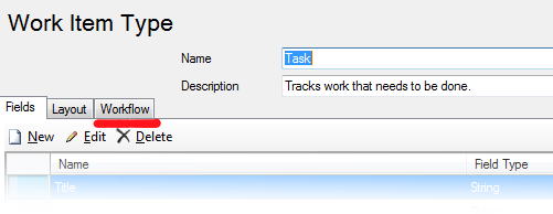
When you open, you will see a screen with settings for the Task element fields, but at this stage we are interested in the Workflow tab.
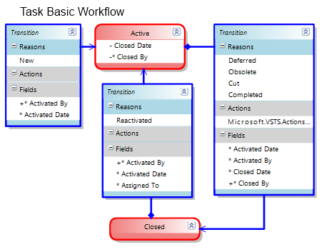
On the Workflow tab, you can see the standard view and location of the State and Transition elements.
Great, now pay attention to the Toolbox and the available elements will not be able to embarrass your mind with an abundance of choices, since there are only two elements that we need.
Naturally, before starting to work, it would be nice to draw on paper or determine for yourself the desired order of states and reasons for the transition, decide on the rules of transition. We assume that we already have such an order in the previous article. Those. we want to end up with something like:

The first nuance that I want to draw your attention to is the creation of the initial state. According to the rules of the scheme, there must be at least one Transition Link element without an initial state. In the diagram, this is a transition to the Proposed state. At this point, there may be difficulties if you create upcoming states and new transitions, and start the scheme with them. Somehow, due to the states or the history of the states, the circuit may not be saved. So my advice will continue more often, after every elementary action.
If you have difficulty creating a new initial state, I recommend first creating an intermediate state with new transitions, saving it. Then the old initial state is transferred to the new element. Most often this allows you to solve the problem. It may also occur due to the current state of the work items in the TFS database itself.
Let's start with a simple one, add a Hold state to our state diagram. On the toolbar, select State and drag it to a convenient place. Generally try to position the elements so that the lines do not intersect, this makes reading difficult.
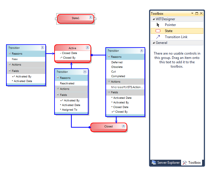
After you have dragged the State element over, you can use the double-click to change the name of the state. However, be precise and attentive. Double clicking outside the title will open the rule editor to populate the fields of the work item. You will see the entered name when editing tasks in the State field. At this stage, we will not need to change the state of other fields when getting into this state, so that we can proceed to the drafting of transitions.
Select Transition Link and select the start and end points of the transition.

A new transition element appears. If you try to save the scheme now, you will get an error, even two.
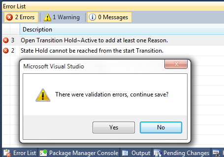
The “main” mistake that I want to draw attention to is: Open Transition Hold ~ Active to add at least one Reason. The second error is also important, indicating an unattainable state, which should not be. So, each transition to the state must have a reason for the transition .
To eliminate this error, double-click the header of the transition element so that the following window appears:

This window is not modal, so be careful, it is easy to lose behind other windows. And it does not “bind” to the studio icon in the taskbar, like other studio windows. Look at the screenshot below.

You may notice that there is no double frame, as we say in Word. Although the edit transition window is open.
So, in the window that appears, we will need the second Reason tab, in which we can enter the required data.

You can edit the values either by clicking on Edit , or by double-clicking on the highlighted line. As you can see from the interface, you can specify a default value. When you start editing, a new screen will appear in size completely matching the first one and overlapping it. It is also not modal and all these windows are very easy to lose.

The second tab, we still do not need. But on it you can configure some rules for other fields of the task.

Adding / deleting new causes / conditions of transition occurs by pressing the corresponding buttons.
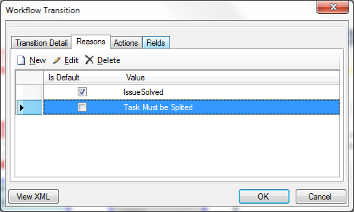
Switching the default values is not performed from this screen but requires entering the condition editing mode.
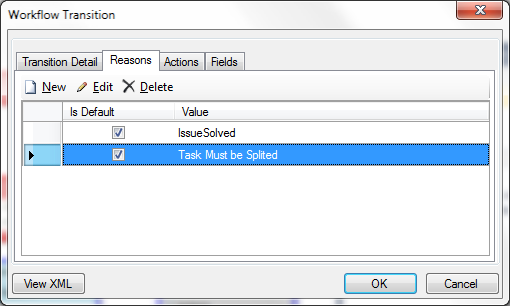
In this case, the validation for the presence of two elements with the “default” marker does not occur, so be careful. The result is the following form:

Here I have already added another transition from Active to Hold and set a condition. After that, everything is well preserved.
Consider further possible changes in the transition from one state to another. For example, after the transition from the Hold state to the Active state. Suppose we want to change the values of some fields, or guarantee their immutability.
To do this, open the transition element again for editing and go to the Fields tab.
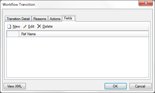
When you add a new field, we get a new screen, where you can select the fields to fill. In the screenshot, green fields are labeled for constructing quite complex conditions, with only red fields possible basic checks. Unfortunately, most of the rules are verified by scientific method.

For example, I want the AreaPath field not to lose its value during the transition from one state to another. For this, I select the field of interest from the drop-down list.
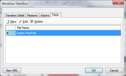
I proceed to edit its rules:

I choose a rule
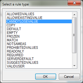
Then a window appears asking for which user groups it will act. If you leave the fields empty, it will work for all

Then I press OK in all windows until they disappear. As a result, we get the view as in the screenshot:

If you try to save, we get such a warning.

If it is possible to overcome this, it is difficult, and it is necessary to write additional libraries, which I have not done. Well, and besides, it is possible to organize it better with the help of other means, like, say, TFS Aggregator. It is rather a topic for a separate article. But for all fields from the space of Microsoft.VSTS. * Rules will work. This can be seen by looking at other states. The field for experiments in general is!
Attentive and experienced readers probably noticed that for some transitions the Action field is filled, and if we recall, when the Check-In is performed, the element automatically changes to another state. Unfortunately, only the Microsoft.VSTS.Actions.Checkin event is available by default. These events are only markers for triggering other TFS components. Unfortunately, there is no information in MSDN how to implement your events, how to write your own component that will respond / read such values from the Actions section in the transition. Although it would be useful. For example, when younger developers do not check the code in the main branch, but put the code on the shelf, as a result of which the task goes to the Need Review state.
In general, this is almost all the possibilities for setting up a state diagram. Everything else is just a repetition of these actions. I hope this will help you in the implementation of your ideas for improving the development process.
After installing TFS Power Tools, a new item in the Tools menu should appear in VS.

')
The screenshot already shows what needs to be done in order to start editing task elements. Tools> Process Editor> Work Item Types> Open WIT from Server. This choice will allow you to immediately get the changes on the server. In general, all the items in the last menu speak for themselves and with minimal experimentation you can get an idea of their action.
After selecting the Open WIT from Server item, you will be prompted to select a TFS Server for connection, after which you will see your project collections and the projects themselves. You must select the project in which you want to make changes and then there will be the final step - the choice of the element to be edited.

As an experimental element we can take Task.
When you open, you will see a screen with settings for the Task element fields, but at this stage we are interested in the Workflow tab.

On the Workflow tab, you can see the standard view and location of the State and Transition elements.

Great, now pay attention to the Toolbox and the available elements will not be able to embarrass your mind with an abundance of choices, since there are only two elements that we need.
Naturally, before starting to work, it would be nice to draw on paper or determine for yourself the desired order of states and reasons for the transition, decide on the rules of transition. We assume that we already have such an order in the previous article. Those. we want to end up with something like:

The first nuance that I want to draw your attention to is the creation of the initial state. According to the rules of the scheme, there must be at least one Transition Link element without an initial state. In the diagram, this is a transition to the Proposed state. At this point, there may be difficulties if you create upcoming states and new transitions, and start the scheme with them. Somehow, due to the states or the history of the states, the circuit may not be saved. So my advice will continue more often, after every elementary action.
If you have difficulty creating a new initial state, I recommend first creating an intermediate state with new transitions, saving it. Then the old initial state is transferred to the new element. Most often this allows you to solve the problem. It may also occur due to the current state of the work items in the TFS database itself.
Let's start with a simple one, add a Hold state to our state diagram. On the toolbar, select State and drag it to a convenient place. Generally try to position the elements so that the lines do not intersect, this makes reading difficult.

After you have dragged the State element over, you can use the double-click to change the name of the state. However, be precise and attentive. Double clicking outside the title will open the rule editor to populate the fields of the work item. You will see the entered name when editing tasks in the State field. At this stage, we will not need to change the state of other fields when getting into this state, so that we can proceed to the drafting of transitions.
Select Transition Link and select the start and end points of the transition.

A new transition element appears. If you try to save the scheme now, you will get an error, even two.

The “main” mistake that I want to draw attention to is: Open Transition Hold ~ Active to add at least one Reason. The second error is also important, indicating an unattainable state, which should not be. So, each transition to the state must have a reason for the transition .
To eliminate this error, double-click the header of the transition element so that the following window appears:

This window is not modal, so be careful, it is easy to lose behind other windows. And it does not “bind” to the studio icon in the taskbar, like other studio windows. Look at the screenshot below.

You may notice that there is no double frame, as we say in Word. Although the edit transition window is open.
So, in the window that appears, we will need the second Reason tab, in which we can enter the required data.

You can edit the values either by clicking on Edit , or by double-clicking on the highlighted line. As you can see from the interface, you can specify a default value. When you start editing, a new screen will appear in size completely matching the first one and overlapping it. It is also not modal and all these windows are very easy to lose.

The second tab, we still do not need. But on it you can configure some rules for other fields of the task.

Adding / deleting new causes / conditions of transition occurs by pressing the corresponding buttons.

Switching the default values is not performed from this screen but requires entering the condition editing mode.

In this case, the validation for the presence of two elements with the “default” marker does not occur, so be careful. The result is the following form:

Here I have already added another transition from Active to Hold and set a condition. After that, everything is well preserved.
Consider further possible changes in the transition from one state to another. For example, after the transition from the Hold state to the Active state. Suppose we want to change the values of some fields, or guarantee their immutability.
To do this, open the transition element again for editing and go to the Fields tab.

When you add a new field, we get a new screen, where you can select the fields to fill. In the screenshot, green fields are labeled for constructing quite complex conditions, with only red fields possible basic checks. Unfortunately, most of the rules are verified by scientific method.

For example, I want the AreaPath field not to lose its value during the transition from one state to another. For this, I select the field of interest from the drop-down list.

I proceed to edit its rules:

I choose a rule

Then a window appears asking for which user groups it will act. If you leave the fields empty, it will work for all

Then I press OK in all windows until they disappear. As a result, we get the view as in the screenshot:

If you try to save, we get such a warning.

If it is possible to overcome this, it is difficult, and it is necessary to write additional libraries, which I have not done. Well, and besides, it is possible to organize it better with the help of other means, like, say, TFS Aggregator. It is rather a topic for a separate article. But for all fields from the space of Microsoft.VSTS. * Rules will work. This can be seen by looking at other states. The field for experiments in general is!
Attentive and experienced readers probably noticed that for some transitions the Action field is filled, and if we recall, when the Check-In is performed, the element automatically changes to another state. Unfortunately, only the Microsoft.VSTS.Actions.Checkin event is available by default. These events are only markers for triggering other TFS components. Unfortunately, there is no information in MSDN how to implement your events, how to write your own component that will respond / read such values from the Actions section in the transition. Although it would be useful. For example, when younger developers do not check the code in the main branch, but put the code on the shelf, as a result of which the task goes to the Need Review state.
In general, this is almost all the possibilities for setting up a state diagram. Everything else is just a repetition of these actions. I hope this will help you in the implementation of your ideas for improving the development process.
Source: https://habr.com/ru/post/147295/
All Articles