Do you still think that plugging a pair of wires into the Arduino is DIY?
The other day, to a fellow SWG, the moderator of my forum, an experienced electronics engineer with a 40-year-old experience, at least experienced nostalgic mood, and he began uploading archived photos of his designs from the 80s. And after that, the rest were drawn up. I couldn’t go past such a delight and allowed myself to make a small compilation of the old hardcore era of total DIY.
SWG:
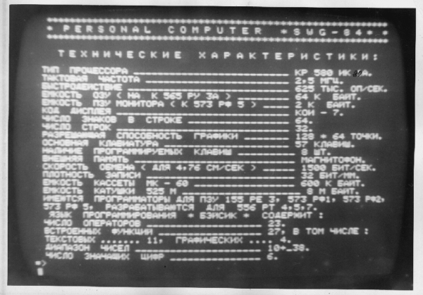
“A computer based on the MICRO-80 from Radio 83g, compatible with it in software and hardware, although it was made in its own way ... From what we managed to get.
For example, the system bus was not on bidirectional buffers, but with an open collector (well, I didn’t have my 589AP16 and AP26 yet). Yes, and the schemes of almost all the modules had to be done in their own way. Nevertheless, everything worked. And all the later published programs in Radio, and even for the RC-86 that appeared later and Mikroshi, we managed to adapt it to our own. Well, he himself has already written something. On Asma, on Baysik.
')
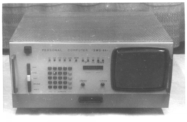
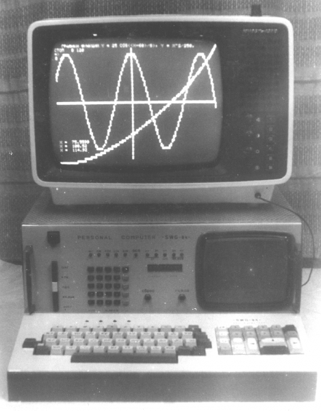
That's actually the computer itself. At first I used the built-in display on the 16th handset. But it was too small, I had to buy a TV Youth - 406D (my eyes are more expensive!), With a tube of 31 cm. That was already gorgeous ...
The keyboard was made separately. Either it was directly stuck close, through a 24-pin, 2-row connector, or it was connected with a cable — an extension of 1.5 to 2.5 meters in length.
On the face there is a technical (also called "engineering") console.

With it, you can intercept the control of the system bus, transfer the processor to the stepping mode, set the address and data on the bus, write data to the memory cells and RAM. Also catch matching gates at a given address (with standby on it or without it), see the main bus signals on the LED array, as well as the data and address in hexadecimal form on the ALS318 indicator (under the LEDs). Entering addresses and data - from the keyboard of the remote control in hexadecimal form.
Large buttons below the power switch:
1. Putting the processor into stepping mode.
2. Turn on the technical keypad.
3. Enabling direct access from the console to the memory.
4. Enabling direct access from the console to the address area of input / output devices.
5. Automatic stop by matching the address on the system bus with the address specified on the remote control. Convenient for debugging. Usually, after stopping the program at the desired address, it was possible to run the program step by step, view any memory cells, or just give the processor commands from the console.
Small buttons (from calculator) - input of hexadecimal values (0-9 and AF buttons), setting the address from the console to the system bus, writing data, reading data at a given address, increment and decrement for the address and data, sequential writing from the auto-increment of the address, something else (I don’t remember everything, it’s been a long time) ...
On the 9th digit indicator there are 4 16-bit digits of the console or system bus addresses, two 16-bit digits of the console data, and two - system bus data.
Under the indicator there are round buttons: system reset and ready button for jog mode.
A row of LEDs:
M1 is the system bus signal at the beginning of each command cycle.
The coolant is a signal of the state of the device's stand-by.
RPR - signaling the resolution of interrupts.
STK - a sign of the processor with the stack.
BUF - I do not remember, it seems, the indication of the connection of the buffer of the console to the system bus.
OST - signaling the processor stop status.
Ch ZU - signal read RAM.
Zp ZU - signal recording RAM.
WH CRC - vector reading from the interrupt controller.
THU BB - read I / O signal.
- Input-output recording signal.
From this technical panel I tested the computer for the first time, then from it I wrote the codes for the display character generator and the MONITOR utility program in 573RF2 - something like a modern BIOS on computers. There are routines for working with co-aviature, a display, a tape recorder, tests and memory dumps, and much more. ”
On the 24-pin connector for the keyboard, 8 data bits, 8 bits of the address, read and write signals for input / output devices, ground, + 5v power (and it seems +12, I don’t remember), a ready signal, maybe something else (too lazy to search for documentation).
This connector also connected programmers through a splitter, a punched tape reader, a self-made printer, a matrix one, with two-step control (carriage drive and paper pulling), and an 8-needle head, directly from the computer. In the printer there were only keys and several sensors on optocouplers (the beginning and end of the lines, the positions of the rotor of the carriage drive of the carriage, the presence of paper). Sensors were also polled by the computer. The entire print driver program in the computer took less than a kilobyte in the ROM. Programmers write and read programs - tens of bytes.
This computer plowed me from 84 to 91 years old ... And later, as a programmer of ROM of all sorts, I used it.
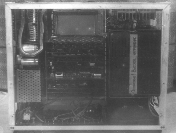
Insides
And then Comrade ShadS came and broke off the brain of a murderous mouse for the Spectrum.
ShadS :
“A long time ago, I had a Spectrum, and of course, the ARTStudio program.
At that time, IBM computers that had a mouse and all that became popular. And I like the passion I wanted to figure out the mouse on the Spectrum, so that the cursor does not drive the buttons but on an adult ... ...
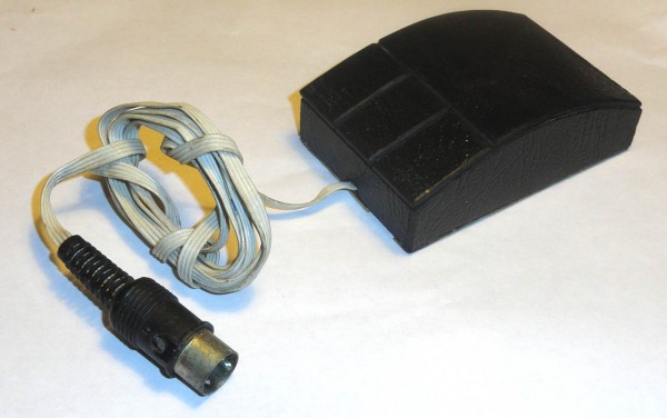
In short, this is what I stuck to the Spectrum, although now from contemplating this - the sensations are not unambiguous (a rusty bunch of incomprehensibility), but it worked ... ... Later, I stuck the Aybiems mouse, but at the very beginning, I didn’t have enough money for it, I remember, but he blinded himself ... "
Very solid from the outside, almost like a factory, if not to find fault.
And the brutal samopal inside:
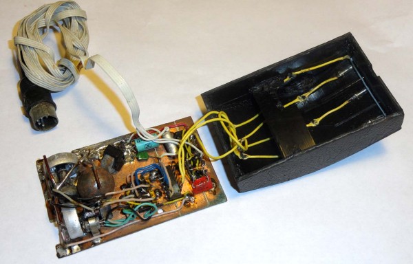
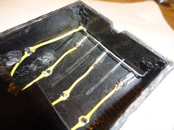
Pay attention to the implementation of buttons. DIY only! Only hardcore!
Logics

Pay attention to the green capacitor. Straight over the two blue wiring. This is the famous capacitor of the KM series. Due to the presence of some rare metals (like palladium), a huge amount of Soviet electronics did not survive to this day. Broke to scrap cleaned: (
Mechanics
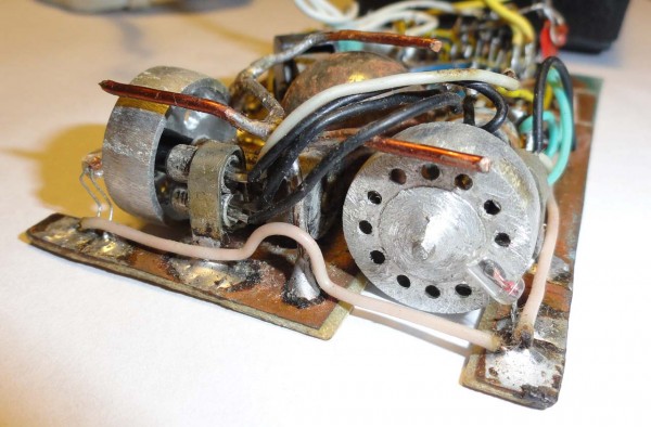
Damn, that's cool. Even self-made rollers, and the optocoupler of the bulb (sic!) And photoresistors.
And did it really work? !!! Surprised question the inhabitants and received an answer.
“It doesn't really happen. There in the mouse, pure logic was there, which converted signals from photodiodes to TTL, all photodiodes and buttons were brought to the shift register, and were sequentially polled by an external device.
As an external device, there was a small block on the Z80 processor, which regularly polled and accumulated coordinate data, buttons, and also waited for calls from the Spectrum.
Spectrum, when it was convenient for him to make a request for this block and received the actual data of coordinates and buttons.
Interestingly, I integrated this business into ARTStudio. It turned out that all the memory for the program was crammed and there was no free space where the driver could have been shoved. Then I calculated the place in the program where there was some function I did not need, nafig cut its code (naturally shut the call to the former function), and in the free space I wrote down the processing code for the mouse ... "
SWG:
“A computer based on the MICRO-80 from Radio 83g, compatible with it in software and hardware, although it was made in its own way ... From what we managed to get.
For example, the system bus was not on bidirectional buffers, but with an open collector (well, I didn’t have my 589AP16 and AP26 yet). Yes, and the schemes of almost all the modules had to be done in their own way. Nevertheless, everything worked. And all the later published programs in Radio, and even for the RC-86 that appeared later and Mikroshi, we managed to adapt it to our own. Well, he himself has already written something. On Asma, on Baysik.
')
That's actually the computer itself. At first I used the built-in display on the 16th handset. But it was too small, I had to buy a TV Youth - 406D (my eyes are more expensive!), With a tube of 31 cm. That was already gorgeous ...
The keyboard was made separately. Either it was directly stuck close, through a 24-pin, 2-row connector, or it was connected with a cable — an extension of 1.5 to 2.5 meters in length.
On the face there is a technical (also called "engineering") console.
With it, you can intercept the control of the system bus, transfer the processor to the stepping mode, set the address and data on the bus, write data to the memory cells and RAM. Also catch matching gates at a given address (with standby on it or without it), see the main bus signals on the LED array, as well as the data and address in hexadecimal form on the ALS318 indicator (under the LEDs). Entering addresses and data - from the keyboard of the remote control in hexadecimal form.
Large buttons below the power switch:
1. Putting the processor into stepping mode.
2. Turn on the technical keypad.
3. Enabling direct access from the console to the memory.
4. Enabling direct access from the console to the address area of input / output devices.
5. Automatic stop by matching the address on the system bus with the address specified on the remote control. Convenient for debugging. Usually, after stopping the program at the desired address, it was possible to run the program step by step, view any memory cells, or just give the processor commands from the console.
Small buttons (from calculator) - input of hexadecimal values (0-9 and AF buttons), setting the address from the console to the system bus, writing data, reading data at a given address, increment and decrement for the address and data, sequential writing from the auto-increment of the address, something else (I don’t remember everything, it’s been a long time) ...
On the 9th digit indicator there are 4 16-bit digits of the console or system bus addresses, two 16-bit digits of the console data, and two - system bus data.
Under the indicator there are round buttons: system reset and ready button for jog mode.
A row of LEDs:
M1 is the system bus signal at the beginning of each command cycle.
The coolant is a signal of the state of the device's stand-by.
RPR - signaling the resolution of interrupts.
STK - a sign of the processor with the stack.
BUF - I do not remember, it seems, the indication of the connection of the buffer of the console to the system bus.
OST - signaling the processor stop status.
Ch ZU - signal read RAM.
Zp ZU - signal recording RAM.
WH CRC - vector reading from the interrupt controller.
THU BB - read I / O signal.
- Input-output recording signal.
From this technical panel I tested the computer for the first time, then from it I wrote the codes for the display character generator and the MONITOR utility program in 573RF2 - something like a modern BIOS on computers. There are routines for working with co-aviature, a display, a tape recorder, tests and memory dumps, and much more. ”
On the 24-pin connector for the keyboard, 8 data bits, 8 bits of the address, read and write signals for input / output devices, ground, + 5v power (and it seems +12, I don’t remember), a ready signal, maybe something else (too lazy to search for documentation).
This connector also connected programmers through a splitter, a punched tape reader, a self-made printer, a matrix one, with two-step control (carriage drive and paper pulling), and an 8-needle head, directly from the computer. In the printer there were only keys and several sensors on optocouplers (the beginning and end of the lines, the positions of the rotor of the carriage drive of the carriage, the presence of paper). Sensors were also polled by the computer. The entire print driver program in the computer took less than a kilobyte in the ROM. Programmers write and read programs - tens of bytes.
This computer plowed me from 84 to 91 years old ... And later, as a programmer of ROM of all sorts, I used it.
Insides
And then Comrade ShadS came and broke off the brain of a murderous mouse for the Spectrum.
ShadS :
“A long time ago, I had a Spectrum, and of course, the ARTStudio program.
At that time, IBM computers that had a mouse and all that became popular. And I like the passion I wanted to figure out the mouse on the Spectrum, so that the cursor does not drive the buttons but on an adult ... ...
In short, this is what I stuck to the Spectrum, although now from contemplating this - the sensations are not unambiguous (a rusty bunch of incomprehensibility), but it worked ... ... Later, I stuck the Aybiems mouse, but at the very beginning, I didn’t have enough money for it, I remember, but he blinded himself ... "
Very solid from the outside, almost like a factory, if not to find fault.
And the brutal samopal inside:
Pay attention to the implementation of buttons. DIY only! Only hardcore!
Logics
Pay attention to the green capacitor. Straight over the two blue wiring. This is the famous capacitor of the KM series. Due to the presence of some rare metals (like palladium), a huge amount of Soviet electronics did not survive to this day. Broke to scrap cleaned: (
Mechanics
Damn, that's cool. Even self-made rollers, and the optocoupler of the bulb (sic!) And photoresistors.
And did it really work? !!! Surprised question the inhabitants and received an answer.
“It doesn't really happen. There in the mouse, pure logic was there, which converted signals from photodiodes to TTL, all photodiodes and buttons were brought to the shift register, and were sequentially polled by an external device.
As an external device, there was a small block on the Z80 processor, which regularly polled and accumulated coordinate data, buttons, and also waited for calls from the Spectrum.
Spectrum, when it was convenient for him to make a request for this block and received the actual data of coordinates and buttons.
Interestingly, I integrated this business into ARTStudio. It turned out that all the memory for the program was crammed and there was no free space where the driver could have been shoved. Then I calculated the place in the program where there was some function I did not need, nafig cut its code (naturally shut the call to the former function), and in the free space I wrote down the processing code for the mouse ... "
Source: https://habr.com/ru/post/146975/
All Articles