Automatic timer for cleaning teeth
Description
One day I returned from a dentist and realized that it was still worth brushing my teeth for at least two minutes. I use a regular toothbrush, and every time I press the timer button is too lazy. I decided to make a device that itself determines that I took out a brush and catch two minutes.
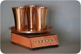
As a basis, I chose an Atmega328p microcontroller, a strain gauge, copper cups, a tray, an alarm call and a sheet of plywood. In this post I will talk about how the device works, what components are used and how the case was assembled.
Let's start with a video that demonstrates the operation of the device:
')
Work algorithm
- Wake up
- Read the current weight with an accuracy of 3 grams
- If the read weight is less than the previous one, play the animation:
- Turn on all lights
- Every 20 seconds off by the light bulb
- Once every 30 seconds, make a "tink" bell, remind you that it is time to clean the other part of the jaw
- Fall asleep for 8 seconds
Strain gauge sensor
Behind this convoluted name lies one of the main components of the device: scales. The strain gauge transforms the mechanical deformation that occurs when the sensor is loaded into an electrical signal. Such sensors are in all electronic scales.
Get this sensor was easy. It is in the cheapest electronic scales:

From the sensor moves four wires. One is connected to the input voltage, one to ground and two to the signal amplifier. The difference in voltages on these two wires determines the weight of the object on the sensor. That is, the heavier the subject, the greater the difference. I note that we are not interested in the exact weight, we just need to determine that the weight has changed (we got a toothbrush). Moreover, it is possible to look once in 5-10 seconds, whether the weight has changed; not scary if the timer does not start instantly.
Component selection
I chose the simplest components. Here is the scheme:
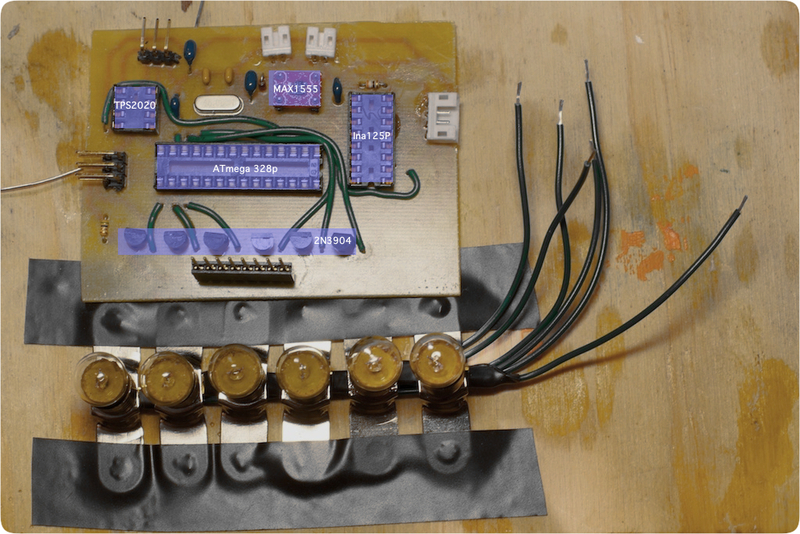
ATMega328p with a crystal at 16Mhz - the "brain" of the device. Perhaps with an easy feed of the Arduino, this controller has become extremely popular among self-taught amateurs. It is very easy to program and difficult to burn.
The Ina125P amplifier is designed specifically to amplify signals from various sensors. The wiring diagram is very simple; the only thing to which it was necessary to pay special attention - this is the magnitude of the resistor that determines the gain. Here is how the amplifier is connected:
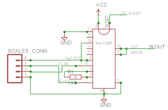
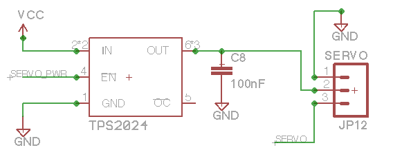
SCALES_CONN - four wires from the sensor.R1 is a resistor that determines the amount of amplification.WOUT is a wire from which it is possible to read the amplified difference between the wires V+IN and V-IN .SC_SLEEP - wire SC_SLEEP amplifier. It is necessary to save energy.The TPS2020 is an excellent switch with very low power consumption when it is turned off (10 μA). It controls servo power:
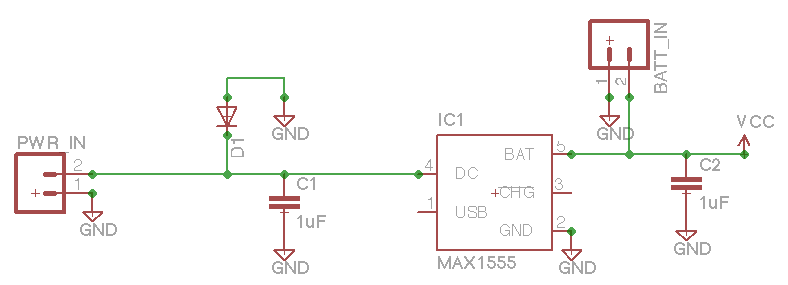
The MAX1555 charger is a chip that controls battery charging. Here is how it is connected:
Transistors 2N3904 - to control the power of light bulbs.
Warm lamp lamps - I decided to use ordinary lamps for exclusively decorative purposes. Since the project suggested a kind of "antique" ordinary LEDs could spoil the impression. Lamps light up less frequently and do not eat up the battery too much. Now the device works the third week on one charge.
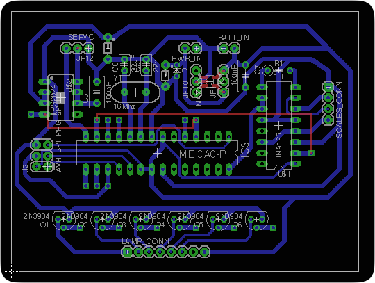
Board assembly
I collected the board by photoresistive method . Here is the sketch:
Board under the lamp:

Those interested can get acquainted with the scheme in the Eagle format and the source code of the project .
Housing assembly
It was almost as interesting to assemble the device case as designing a circuit and writing code. It all started with a sheet of plywood and a drawing in Inkscape. I managed to rent a laser cutter: a drawing is sent to it, like a printer, a sheet of plywood is put into the work area, the focus is adjusted and the machine accurately and accurately cuts out the required parts. Here's what it looks like:
I used super glue to assemble the parts. To increase the adhesive area, all the joints were reinforced with small corners of the same plywood. I found that it makes sense to make these corners with a margin to strengthen the body later.

Body ready for painting:

I used two coats of paint and two coats of varnish. Before painting, I walked across the entire structure with a small pelt.
Here are the components:
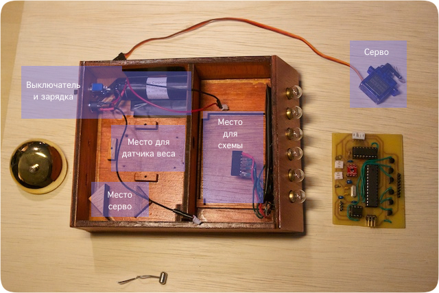
All seams were sealed with glue gun. In this project it was very important that the electronics were well isolated. The device is located next to the sink, so that it will definitely spray. The partition in the middle should save the circuit if water leaks into the case.
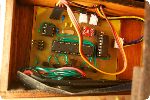
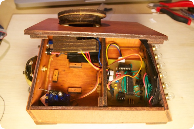
Here's what the connected circuit looks like from the inside:
This photo shows the bell mechanism (servo with a hammer) and a tray stand (on top, on the lid):
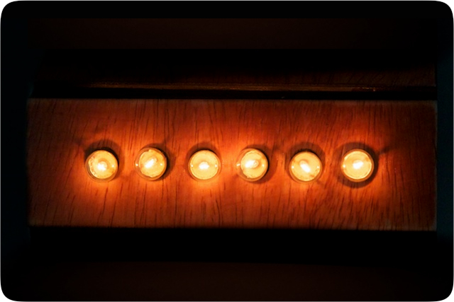
If you brush your teeth at night with the lights off, it sometimes seems that the device is watching you with six burning eyes:
Conclusion
I will be glad to answer any questions. I would also welcome any comments: I just recently began studying microelectronics.
I hope this device will make my visits to the dentist more enjoyable. And even more, I hope that it will inspire you to create your crazy inventions.

Source: https://habr.com/ru/post/146915/
All Articles