Anatomy of old tube electronics
In the old house I got two very old lamp receivers, more precisely, a radio tape recorder (receiver + tape recorder) and a radio tape recorder (receiver + record player).
I don’t raise such good things in my hand - it was decided to disassemble them and eventually make such an authentic old receiver. But in the process of disassembling, it became clear that I had a living history of radio engineering in front of me, I captured something and now I post it with detailed comments.
There are many large images under the cut, the total size is about 20 MB
')
So, instance number 1 (this receiver + tape recorder + player Romance 105).
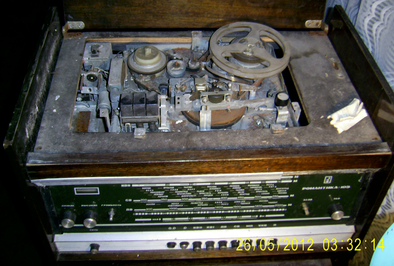
We first look at the remains of the tape recorder, but first - a few words about the recording itself.
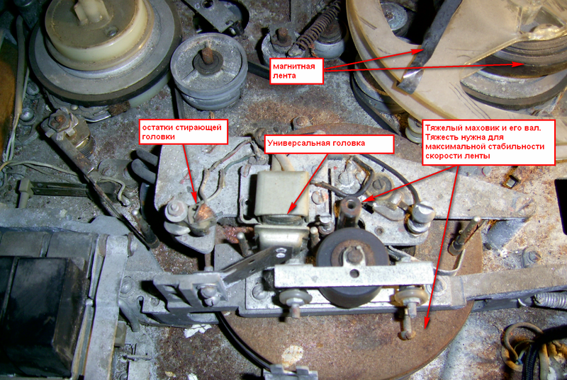
The tape moves ("stretches") past the head. The head is just a core coil.
Tape recording
If a current with a signal is fed into the coil, the magnetic flux will change in proportion to the signal and magnetize the moving tape, thus recording the signal on it.
Reproduction
When the magnetized tape moves past the head in it due to changes in the magnetic field from the tape, a voltage is induced, which is then amplified - the sound is produced, the same one that was recorded on the tape.
This is very rude, the reality is much more complicated, but the principle is the same.
Usually the recording and playback heads are combined, this head was called universal, but there were designs with separate recording and playback heads.
Erasing
For erasing, a separate head serves; when erasing, a relatively high frequency current, tens to hundreds of kilohertz, was applied to it from a special generator. Repeated reversal of tape sections led to erasing the recorded one.
In cheap Chinese tape recorders, a permanent magnet was used as the erase head, sometimes a multi-plus one.
By the way, the principle of recording information in modern hard drives is the same: a magnetic surface moving past the head.
So:
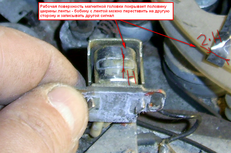
Magnetic head close up
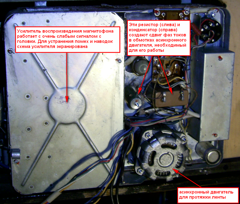
We remove the panel of the tape recorder, we look the other way - there is more interestinggold and diamonds.
We talked about erasure. Here is the erase generator a separate lamp
And, of course, the power supply system
Receiver
Before dissecting the receiver, a few words about the principles of reception.
The simplest option: select the desired frequency from the antenna -> amplify it -> detect, that is, select the sound - amplify the sound:
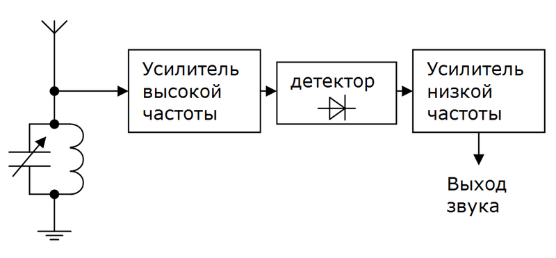
Such receivers were called “direct gain receivers”, but are not currently used in real-time radio reception. Why? The whole chip in the allocation of useful frequency.
The frequency is allocated oscillatory circuit, and if we want to take different stations, the circuit must be rebuilt. Moreover, for normal reception, how many high frequency amplification stages are there - everything needs to be rebuilt.
This entails a lot of problems, so this is not done.
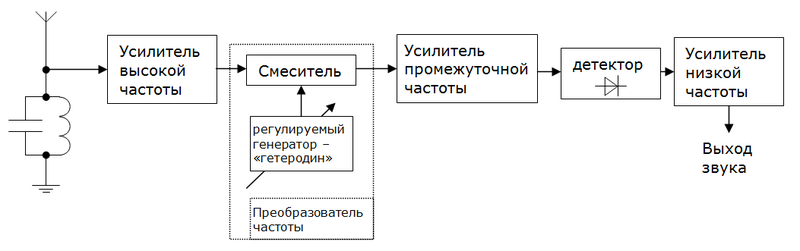
It is done like this: The frequency of any input signal is converted to some constant frequency (it is called intermediate), at which the main amplification occurs. Further, without features: detection and amplification of sound.
The principles of radio reception and receiver design are a separate, extremely interesting topic, but I’ll allow myself not to touch it in detail in this topic.
So, what should be borne in mind when parsing the receiver circuit: in addition to amplifiers, it also has frequency converters - one or more, and there is also a detector.
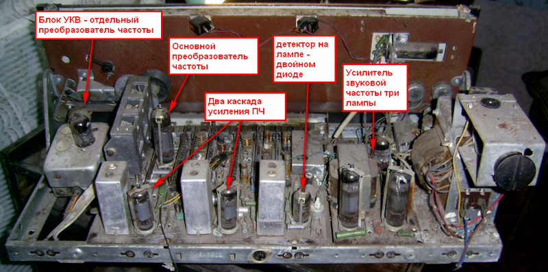
So, our radio, receiver:
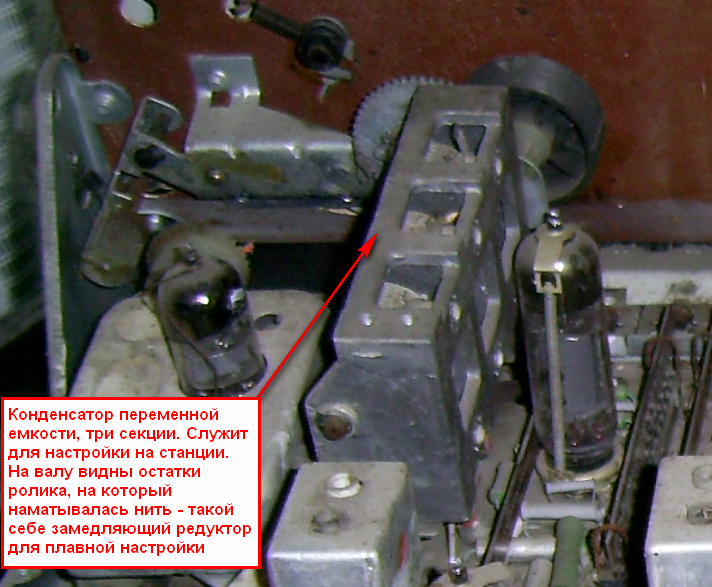
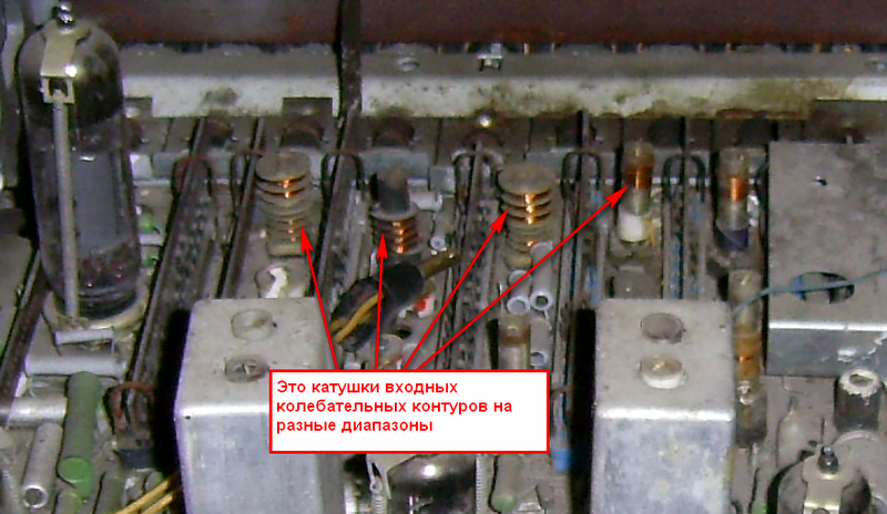
Slightly more interesting sites
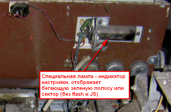
Indicator - saved and will be used as beautiful
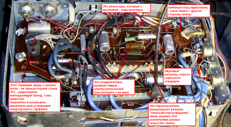
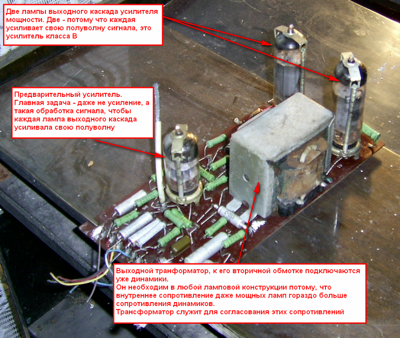
Separately, the audio amplifier is the one that gives a “warm tube sound”
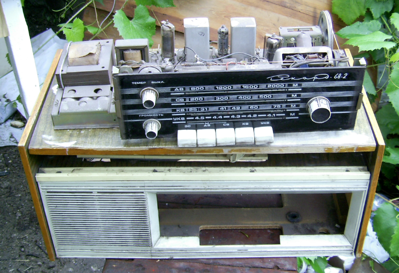
The second candidate is a simpler radiogram, Record-68 (year of release - 1971).
Since the receivers are simpler and have already been studied, we will manage with a less detailed photo report.
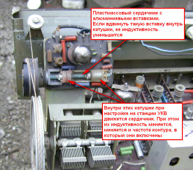
Interesting touch: VHF tuning is performed using a coil in which the core moves - “variometer”
The final
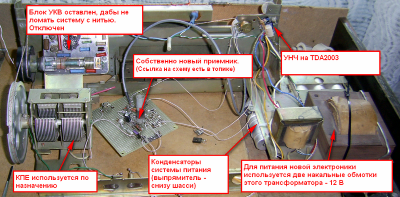
I said at the beginning of the topic that I wanted to make an authentic receiver. Actually, here it is - only the body remains from the old one. Takes HF, here is the scheme .
Am I pleased with the receiver? Good question.
The circuit on relatively new transistors and microcircuits catches the radio much better, sounds louder and cleaner.
But still there is nothing in it. Soul, I suppose ...
I will make a new receiver - on the lamps.
I don’t raise such good things in my hand - it was decided to disassemble them and eventually make such an authentic old receiver. But in the process of disassembling, it became clear that I had a living history of radio engineering in front of me, I captured something and now I post it with detailed comments.
There are many large images under the cut, the total size is about 20 MB
')
So, instance number 1 (this receiver + tape recorder + player Romance 105).
We first look at the remains of the tape recorder, but first - a few words about the recording itself.
The tape moves ("stretches") past the head. The head is just a core coil.
Tape recording
If a current with a signal is fed into the coil, the magnetic flux will change in proportion to the signal and magnetize the moving tape, thus recording the signal on it.
Reproduction
When the magnetized tape moves past the head in it due to changes in the magnetic field from the tape, a voltage is induced, which is then amplified - the sound is produced, the same one that was recorded on the tape.
This is very rude, the reality is much more complicated, but the principle is the same.
Usually the recording and playback heads are combined, this head was called universal, but there were designs with separate recording and playback heads.
Erasing
For erasing, a separate head serves; when erasing, a relatively high frequency current, tens to hundreds of kilohertz, was applied to it from a special generator. Repeated reversal of tape sections led to erasing the recorded one.
In cheap Chinese tape recorders, a permanent magnet was used as the erase head, sometimes a multi-plus one.
By the way, the principle of recording information in modern hard drives is the same: a magnetic surface moving past the head.
So:
Magnetic head close up
We remove the panel of the tape recorder, we look the other way - there is more interesting
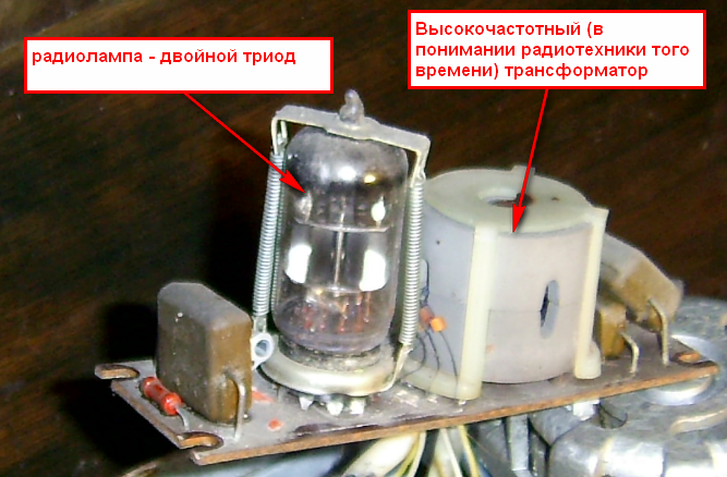
We talked about erasure. Here is the erase generator a separate lamp
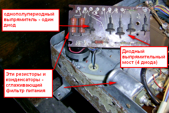
And, of course, the power supply system
Receiver
Before dissecting the receiver, a few words about the principles of reception.
The simplest option: select the desired frequency from the antenna -> amplify it -> detect, that is, select the sound - amplify the sound:
Such receivers were called “direct gain receivers”, but are not currently used in real-time radio reception. Why? The whole chip in the allocation of useful frequency.
The frequency is allocated oscillatory circuit, and if we want to take different stations, the circuit must be rebuilt. Moreover, for normal reception, how many high frequency amplification stages are there - everything needs to be rebuilt.
This entails a lot of problems, so this is not done.
It is done like this: The frequency of any input signal is converted to some constant frequency (it is called intermediate), at which the main amplification occurs. Further, without features: detection and amplification of sound.
The principles of radio reception and receiver design are a separate, extremely interesting topic, but I’ll allow myself not to touch it in detail in this topic.
So, what should be borne in mind when parsing the receiver circuit: in addition to amplifiers, it also has frequency converters - one or more, and there is also a detector.
So, our radio, receiver:
Slightly more interesting sites
Indicator - saved and will be used as beautiful
Separately, the audio amplifier is the one that gives a “warm tube sound”
The second candidate is a simpler radiogram, Record-68 (year of release - 1971).
Since the receivers are simpler and have already been studied, we will manage with a less detailed photo report.
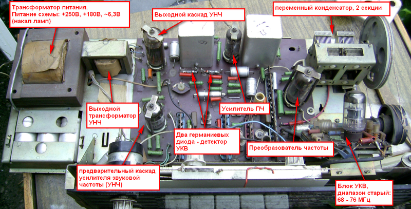
Interesting touch: VHF tuning is performed using a coil in which the core moves - “variometer”
The final
I said at the beginning of the topic that I wanted to make an authentic receiver. Actually, here it is - only the body remains from the old one. Takes HF, here is the scheme .
Am I pleased with the receiver? Good question.
The circuit on relatively new transistors and microcircuits catches the radio much better, sounds louder and cleaner.
But still there is nothing in it. Soul, I suppose ...
I will make a new receiver - on the lamps.
Source: https://habr.com/ru/post/146665/
All Articles