We write the emulator prefix P2, or a little about CHIP16
In my previous short note, I described the principle of building an emulator of the old gaming platform CHIP-8 from the distant 70s. Here we will talk about a kind of heiress - CHIP16. So what is CHIP16?
 CHIP16 - “fictional” game console, which has never existed in the “hardware”. All the specifications for it were developed by enthusiasts from one English-speaking forum . The point is to make emulator writing as simple as possible, to have good documentation and community support. Thereby allowing even beginners in programming to create a fully working emulator from scratch in virtually any programming language. At once I will make a reservation that here I will not give examples of the code of the emulator, the goal is just to tell about this platform. And yes, of course, all Just for fun!
 It all started somewhere in 2010 , since the specification has acquired the version number 1.1, the main shortcomings were eliminated, the main tools were written to create games and other programs for this platform (assembler, debugger, image converter, etc.). The main difference from the same CHIP-8 is the presence of a larger screen resolution, more colors, more arithmetic and other instructions, improved support for sound and no undocumented features.
')
The prefix has a 16-bit processor, memory, two input devices (joysticks such as Dendy), an audio and video subsystem. Consider the whole bunch in more detail.
The processor includes:
The execution of each opcode (processor command) takes exactly one cycle, the processor runs at a frequency of 1 Mhz. Here I will make a reservation that, in fact, as long as the frequency is not clear to the end, and each team performs faster on the emulator than 1 Mhz. Sometimes with maximum emulation speed. In general, while you can not bother about this.
Total 64Kb (65536 bytes). The memory is distributed as follows:
0x0000 - Start of binary data
0xFDF0 - Start of the stack (512 bytes).
0xFFF0 - I / O ports (I / O, to track the status of joysticks).
The screen resolution is 320x240 pixels. The number of colors displayed at one time is 16 from the standard palette.
 It is possible to set your own color palette. The refresh rate of the screen is 60 frames per second, with each frame being set to an internal Vblank flag (every ~ 16ms). The processor has the opportunity to wait for the completion of frame rendering using the VBLNK instruction. The image is formed from sprites, there is no direct access to the video memory. In addition to the main layer where sprites are drawn, there is a background layer that fills the entire screen with one of 16 colors.
The screen is not mirrored, so everything that does not fit into the physical coordinates remains behind the screen and is not displayed. From this it follows that sprites may have negative coordinates (or exceeding 320x200). If you take a 4x4 pixel sprite and, for example, give the command to draw it according to the coordinates (-2, -2), then in the upper left corner of the screen a part of the sprite with a size of 2x2 pixels will be displayed.
So, as all possible colors in a palette 16, then 4 bits are necessary to encode one point on the screen. One byte is a block of two points. The minimum sprite consists of one byte - it is a sprite of 2x1 (two points). Let's take a look at how to encode an 8x5 pixel sprite, considering that the white color in the standard palette is the color with the index 0xFh, and the black color with the index 0x1h
Total, 20 bytes. That is (8 x 5) / 2 = 20
If the new sprite overlaps any already existing pixels on the screen (with the exception of pixels with zero color - they are transparent), then the carry flag is set. Thus, it is possible to track collisions and collisions of objects on the screen in games.
To assign your own color palette instead of the standard, there is a special PAL processor command. Each color palette consists of 3 bytes, in RGB format. Since only 16 colors are used, the PAL command reads an array of 48 bytes from memory and assigns RGB components to colors with indices 0x0, 0x1, .., 0xF. The palette is replaced after the processor receives the VBLNK command .
In the initial versions there was an opportunity to play only three fixed tones (500Hz, 1000Hz, 1500Hz) for a certain number of milliseconds, but then the ability to use an ADSR sound generator was added
Access to information from the joysticks is carried out by means of memory-mapped I / O ports. The first joystick at 0xFFF0, the second - 0xFFF2.
Bit [0] - Up (Up)
Bit [1] - Down (Down)
Bit [2] - Left (Left)
Bit [3] - Right (Right)
Bit [4] - Select
Bit [5] - Start (Start)
Bit [6] - A
Bit [7] - B
Bit [8 - 15] - Not used, always zero.
Thus, by reading the value from the memory at 0xFFF0 into the register and checking the corresponding bits set, you can track which buttons are currently pressed on the first joystick.
The ROM file (standard .c16 extension) contains the header and binary data immediately after the header. Information from the header can be used to determine the version of the specification, etc. The header has a constant size of 16 bytes. Its format is:
Immediately behind him begin binary data, which must always be read into memory starting at address 0x0000. The command counter must be set according to the value in the header. As a rule, this is 0x0000.
ROM files may not have a header at all, since it was introduced into the specification relatively recently.
Conditions are used for conditional jump (jumps) commands or conditional subroutine call commands. For example: “jle label” or “cno some_label2”. In brackets is the state of the flags when the condition is triggered.
You can also use alternative mnemonics:
Any CHIP16 opcode takes exactly 4 bytes (32 bits).
HH - high byte.
LL - Junior Fight.
N - nibble (4-bit value).
X, Y, Z - 4-bit register identifier.
You can read more, as I said, on the English-speaking forum.
- The first (and already outdated and closed) topic with a discussion of CHIP16
- The second topic with the discussion (main). Here all the information is collected in the first post of the topic. There is a specification, tools, examples of programs. Registration is required to download something from the forum.
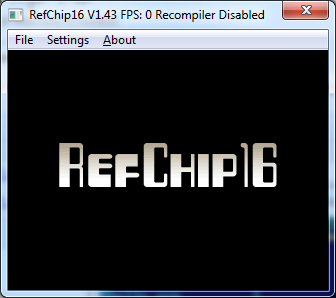 A good RefCHIP16 emulator: code.google.com/p/refchip16/downloads/list C ++ sources, there is a possibility of both simple interpretation and AOT (Ahead Of Time) compilation, which undoubtedly delivers. Perhaps the only normal emulator that correctly processes specification 1.1 (especially ADSR sound).
A bit outdated set of games, demos and test images for CHIP16. In the same place source codes on the assembler for the majority of programs: rghost.ru/38862474 New games and programs are laid out in the thread on the forum.
Programs and games for CHIP16 are overwhelmingly written in assembler. You can download it here: code.google.com/p/tchip16/downloads/list For example, take our sprite from this topic (arrow) and display it on the screen. To do this, open any text editor, create an empty habr.asm file and write commands to it:
Then we compile the program using this command:
Then open the resulting habr.c16 file in the emulator and enjoy the view of the black arrow on a white background :)
To debug complex algorithms, you can use my debugger chip16debugger: code.google.com/p/chip16debugger/downloads/list

While the alpha version, govnokod, certainly with bugs, but better than nothing. Sometimes it really helps to catch a bug.
Well, for example, some compiler (or translator) from a high-level language. For example, I tried to write a translator from an Pascal-like language. Of course, something happened, but it is clearly not enough for a full-fledged language. Here such programs could write on it:
The output was a ton of assembler govnokod, which was compiled by the above assembler tchip16. In the end, it somehow worked and gave the following picture:
Unfortunately, I scored, I didn’t have enough skill to bring everything to release or at least beta.
 What else ... Oh yes, there was an interesting case - they wanted to stir up the CHIP16 demo component, such as writing demos for a subject. Well, what, old school, resources are limited, this is not a shooter with gigami operatives. In theory, you can completely spin the old effects, as though there is no frame buffer, but there are 32Kb operatives under the sprite the size of the whole screen. And 32Kb per code remains. It will be even without blinking the screen. My small demo sinedots (such points are spinning in space, it turns out to be three-dimensional). The truth is, I stepped here, and I’d output the dots exactly with dots (sprites of one byte) because of what the blink is.
You can also create the entire platform in hardware (for fans of FPGAs and other transistors). And I might write my emulator for this piece of iron:
And let it not quite hardware in terms of hardware (there is a normal MIPS processor), but it is still interesting.
Good luck to all!
CHIP16 - “fictional” game console, which has never existed in the “hardware”. All the specifications for it were developed by enthusiasts from one English-speaking forum . The point is to make emulator writing as simple as possible, to have good documentation and community support. Thereby allowing even beginners in programming to create a fully working emulator from scratch in virtually any programming language. At once I will make a reservation that here I will not give examples of the code of the emulator, the goal is just to tell about this platform. And yes, of course, all Just for fun!Prehistory
It all started somewhere in 2010 , since the specification has acquired the version number 1.1, the main shortcomings were eliminated, the main tools were written to create games and other programs for this platform (assembler, debugger, image converter, etc.). The main difference from the same CHIP-8 is the presence of a larger screen resolution, more colors, more arithmetic and other instructions, improved support for sound and no undocumented features.')
The prefix has a 16-bit processor, memory, two input devices (joysticks such as Dendy), an audio and video subsystem. Consider the whole bunch in more detail.
CPU
The processor includes:
- One 16-bit command counter (PC)
- One 16-bit stack pointer (SP)
- Sixteen 16-bit general purpose registers (R0 - RF)
- One 8-Bit Flag Register
The execution of each opcode (processor command) takes exactly one cycle, the processor runs at a frequency of 1 Mhz. Here I will make a reservation that, in fact, as long as the frequency is not clear to the end, and each team performs faster on the emulator than 1 Mhz. Sometimes with maximum emulation speed. In general, while you can not bother about this.
Memory
Total 64Kb (65536 bytes). The memory is distributed as follows:
0x0000 - Start of binary data
0xFDF0 - Start of the stack (512 bytes).
0xFFF0 - I / O ports (I / O, to track the status of joysticks).
Video
The screen resolution is 320x240 pixels. The number of colors displayed at one time is 16 from the standard palette.
| Index in the palette | Sixteen. value | Colour |
|---|---|---|
| 0x0 | 0x000000 | Black, transparent on the background layer |
| 0x1 | 0x000000 | The black |
| 0x2 | 0x888888 | Gray |
| 0x3 | 0xBF3932 | Red |
| 0x4 | 0xDE7AAE | Pink |
| 0x5 | 0x4C3D21 | Dark brown |
| 0x6 | 0x905F25 | Brown |
| 0x7 | 0xE49452 | Orange |
| 0x8 | 0xEAD979 | Yellow |
| 0x9 | 0x537A3B | Green |
| 0xA | 0xABD54A | Light green |
| 0xB | 0x252E38 | Navy blue |
| 0xC | 0x00467F | Blue |
| 0xD | 0x68ABCC | Light blue |
| 0xE | 0xBCDEE4 | Sky blue |
| 0xF | 0xFFFFFF | White |
It is possible to set your own color palette. The refresh rate of the screen is 60 frames per second, with each frame being set to an internal Vblank flag (every ~ 16ms). The processor has the opportunity to wait for the completion of frame rendering using the VBLNK instruction. The image is formed from sprites, there is no direct access to the video memory. In addition to the main layer where sprites are drawn, there is a background layer that fills the entire screen with one of 16 colors.The screen is not mirrored, so everything that does not fit into the physical coordinates remains behind the screen and is not displayed. From this it follows that sprites may have negative coordinates (or exceeding 320x200). If you take a 4x4 pixel sprite and, for example, give the command to draw it according to the coordinates (-2, -2), then in the upper left corner of the screen a part of the sprite with a size of 2x2 pixels will be displayed.
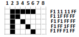
So, as all possible colors in a palette 16, then 4 bits are necessary to encode one point on the screen. One byte is a block of two points. The minimum sprite consists of one byte - it is a sprite of 2x1 (two points). Let's take a look at how to encode an 8x5 pixel sprite, considering that the white color in the standard palette is the color with the index 0xFh, and the black color with the index 0x1h
Total, 20 bytes. That is (8 x 5) / 2 = 20
If the new sprite overlaps any already existing pixels on the screen (with the exception of pixels with zero color - they are transparent), then the carry flag is set. Thus, it is possible to track collisions and collisions of objects on the screen in games.
To assign your own color palette instead of the standard, there is a special PAL processor command. Each color palette consists of 3 bytes, in RGB format. Since only 16 colors are used, the PAL command reads an array of 48 bytes from memory and assigns RGB components to colors with indices 0x0, 0x1, .., 0xF. The palette is replaced after the processor receives the VBLNK command .
Sound
In the initial versions there was an opportunity to play only three fixed tones (500Hz, 1000Hz, 1500Hz) for a certain number of milliseconds, but then the ability to use an ADSR sound generator was added
Input Devices (Joysticks)
Access to information from the joysticks is carried out by means of memory-mapped I / O ports. The first joystick at 0xFFF0, the second - 0xFFF2.
Bit [0] - Up (Up)
Bit [1] - Down (Down)
Bit [2] - Left (Left)
Bit [3] - Right (Right)
Bit [4] - Select
Bit [5] - Start (Start)
Bit [6] - A
Bit [7] - B
Bit [8 - 15] - Not used, always zero.
Thus, by reading the value from the memory at 0xFFF0 into the register and checking the corresponding bits set, you can track which buttons are currently pressed on the first joystick.
Image file format (ROM files)
The ROM file (standard .c16 extension) contains the header and binary data immediately after the header. Information from the header can be used to determine the version of the specification, etc. The header has a constant size of 16 bytes. Its format is:
| Bias | Purpose |
|---|---|
| 0x00 | Magic number 'CH16' |
| 0x04 | Reserved |
| 0x05 | The specification version (the first 4 bits = the main version, the second 4 bits = a sub version, that is, 0.7 = 0x07 and 1.0 = 0x10) |
| 0x06 | ROM file size (not including header, in bytes) |
| 0x0A | Start Address (PC Command Counter Value) |
| 0x0C | CRC32 checksum (not including header, polynomial = 0x04c11db7) |
Immediately behind him begin binary data, which must always be read into memory starting at address 0x0000. The command counter must be set according to the value in the header. As a rule, this is 0x0000.
ROM files may not have a header at all, since it was introduced into the specification relatively recently.
Flag register
| Bit [0] | Reserved |
| Bit [1] | c - carry flag (unsigned overflow) |
| Bit [2] | z - zero flag |
| Bit [3] | Reserved |
| Bit [4] | Reserved |
| Bit [5] | Reserved |
| Bit [6] | o - Overflow (overflow of signed numbers) |
| Bit [7] | n - negative (flag of a negative sign) |
Condition types for conditional jump instructions
Conditions are used for conditional jump (jumps) commands or conditional subroutine call commands. For example: “jle label” or “cno some_label2”. In brackets is the state of the flags when the condition is triggered.
| Z | 0x0 | [z == 1] | Equal (Zero) |
| Nz | 0x1 | [z == 0] | Not Equal (Non-Zero) |
| N | 0x2 | [n == 1] | Negative |
| Nn | 0x3 | [n == 0] | Not-Negative (Positive or Zero) |
| P | 0x4 | [n == 0 && z == 0] | Positive |
| O | 0x5 | [o == 1] | Overflow |
| NO | 0x6 | [o == 0] | No overflow |
| A | 0x7 | [c == 0 && z == 0] | Above (Unsigned Greater Than) |
| AE | 0x8 | [c == 0] | Above Equal (Unsigned Greater Than or Equal) |
| B | 0x9 | [c == 1] | Below (Unsigned Less Than) |
| BE | 0xA | [c == 1 || z == 1] | Below Equal (Unsigned Less Than or Equal) |
| G | 0xB | [o == n && z == 0] | Signed Greater Than |
| Ge | 0xC | [o == n] | Signed Greater Than or Equal |
| L | 0xD | [o! = n] | Signed less than |
| LE | 0xE | [o! = n || z == 1] | Signed Less Than or Equal |
You can also use alternative mnemonics:
| NC | 0x8 | [c == 0] | Not Carry (Same as AE) |
| C | 0x9 | [c == 1] | Carry (Same as B) |
Processor commands
Any CHIP16 opcode takes exactly 4 bytes (32 bits).
HH - high byte.
LL - Junior Fight.
N - nibble (4-bit value).
X, Y, Z - 4-bit register identifier.
| Opcode | Mnemonics | Using | |||||||
|---|---|---|---|---|---|---|---|---|---|
| 00 00 00 00 | NOP | No operation, just one processor cycle | |||||||
| 01 00 00 00 | CLS | Cleaning the screen (the main layer is cleared, the background color is set to the color with index 0) | |||||||
| 02 00 00 00 | VBLNK | Wait for vertical sync. If the frame did not have time to draw, then PC- = 4 | |||||||
| 03 00 0N 00 | BGC N | Set the background color with the index N. If the index is 0, then the background color is black | |||||||
| 04 00 LL HH | SPR HHLL | Set the size of the sprite: width (LL) and height (HH) | |||||||
| 05 YX LL HH | DRW RX, RY, HHLL | Draw a sprite from the address in the HHLL memory on the coordinates specified in the registers X and Y. The result affects the carry flag | |||||||
| 06 YX 0Z 00 | DRW RX, RY, RZ | Draw a sprite from the address in memory, which is indicated by the Z register according to the coordinates specified in the X and Y registers. The result affects the carry flag | |||||||
| 07 0X LL HH | RND RX, HHLL | Put a random number in register X. The maximum value is set to HHLL | |||||||
| 08 00 00 00 | FLIP 0, 0 | Set the display orientation of the sprite. Horizontal flip = NO, vertical flip = NO | |||||||
| 08 00 00 01 | FLIP 0, 1 | Set the display orientation of the sprite. Horizontal flip = NO, vertical flip = YES | |||||||
| 08 00 00 02 | FLIP 1, 0 | Set the display orientation of the sprite. Horizontal flip = YES, vertical flip = NO | |||||||
| 08 00 00 03 | FLIP 1, 1 | Set the display orientation of the sprite. Horizontal coup = YES, vertical coup = YES | |||||||
| 09 00 00 00 | Snd0 | Stop playing sound | |||||||
| 0A 00 LL HH | SND1 HHLL | Play 500Hz HHLL tone milliseconds | |||||||
| 0B 00 LL HH | Snd2 hhll | Play 1000Hz HHLL tone milliseconds | |||||||
| 0C 00 LL HH | SND3 HHLL | Play 1500Hz HHLL tone milliseconds | |||||||
| 0D 0X LL HH | SNP RX, HHLL | Play a sound tone for HHLL milliseconds, in accordance with the current sound generator, set at HHLL | |||||||
| 0E AD SR VT | SNG AD, VTSR | ADSR Sound Generator
| |||||||
| 10 00 LL HH | JMP HHLL | Go to the specified address HHLL | |||||||
| 12 0x LL HH | Jx hhll | Go to the specified HHLL address subject to the condition 'x'. (see Condition Types) | |||||||
| 13 YX LL HH | JME RX, RY, HHLL | Go to the specified address HHLL if the register X is equal to the register Y | |||||||
| 16 0X 00 00 | Jmp rx | Go to address specified in register X | |||||||
| 14 00 LL HH | CALL HHLL | Call a subroutine at HHLL. Saves PC to [SP], increases SP by 2 | |||||||
| 15 00 00 00 | RET | Return from subroutine. Decreases SP by 2 and recovers PC from [SP] | |||||||
| 17 0x LL HH | Cx hhll | If the 'x' condition is met, then the subroutine call. (see Condition Types) | |||||||
| 18 0X 00 00 | CALL RX | Call the subroutine at the address in register X. Saves the PC to [SP], increases the SP by 2 | |||||||
| 20 0X LL HH | LDI RX, HHLL | Put the immediate HHLL value in register X | |||||||
| 21 00 LL HH | LDI SP, HHLL | Set stack pointer to HHLL address. Does not move the old values in the stack to the new address | |||||||
| 22 0X LL HH | LDM RX, HHLL | Put in the register X 16-bit value from the memory at the address HHLL | |||||||
| 22 YX 00 00 | LDM RX, RY | Put in the register X 16-bit value from memory at the address pointed to by the register Y | |||||||
| 24 YX 00 00 | MOV RX, RY | Copy the value of the register Y to the register X | |||||||
| 30 0X LL HH | STM RX, HHLL | Store X register in memory at HHLL | |||||||
| 31 YX 00 00 | STM RX, RY | Store the value of register X in memory at the address in the register Y | |||||||
| 40 0X LL HH | ADDI RX, HHLL | Add the immediate HHLL value to the X register. Affects the flags [c, z, o, n] | |||||||
| 41 YX 00 00 | ADD RX, RY | Add the value of the register Y to the register X. The result is placed in the register X. Affects the flags [c, z, o, n] | |||||||
| 42 YX 0Z 00 | ADD RX, RY, RZ | Add the value of the register Y to the register X. The result is placed in the register Z. Affects the flags [c, z, o, n] | |||||||
| 50 0X LL HH | SUBI RX, HHLL | Subtract the immediate HHLL value from the X register. The result is in the X register. Affects the flags [c, z, o, n] | |||||||
| 51 YX 00 00 | SUB RX, RY | Subtract the value of the register Y from the register X. The result is placed in the register X. Affects the flags [c, z, o, n] | |||||||
| 52 YX 0Z 00 | SUB RX, RY, RZ | Subtract the value of the register Y from the register X. The result is placed in the register Z. Affects the flags [c, z, o, n] | |||||||
| 53 0X LL HH | CMPI RX, HHLL | Subtract the immediate HHLL value from register X. The result is not saved. Affects flags [c, z, o, n] | |||||||
| 54 YX 00 00 | CMP RX, RY | Subtract the value of register Y from register X. The result is not saved. Affects flags [c, z, o, n] | |||||||
| 60 0X LL HH | ANDI RX, HHLL | Logical operation 'And' immediate values of HHLL to the register X. The result in the register X. Affects the flags [z, n] | |||||||
| 61 YX 00 00 | AND RX, RY | Logical operation 'And' values in the register Y to the register X. The result is placed in the register X. Affects the flags [z, n] | |||||||
| 62 YX 0Z 00 | AND RX, RY, RZ | Logical operation 'And' values in the register Y to the register X. The result is placed in the register Z. Affects the flags [z, n] | |||||||
| 63 0X LL HH | TSTI RX, HHLL | Logical operation 'And' direct value HHLL to register X. The result is not saved. Affects flags [z, n] | |||||||
| 64 YX 00 00 | TST RX, RY | Logical operation 'And' values in the register Y to the register X. The result is not saved. Affects flags [z, n] | |||||||
| 70 0X LL HH | ORI RX, HHLL | Logical operation 'OR' immediate HHLL values to the register X. The result in the register X. Affects the flags [z, n] | |||||||
| 71 YX 00 00 | OR RX, RY | Logical operation 'OR' values in register Y to register X. The result is placed in register X. Affects flags [z, n] | |||||||
| 72 YX 0Z 00 | OR RX, RY, RZ | Logical operation 'OR' values in the register Y to the register X. The result is placed in the register Z. Affects the flags [z, n] | |||||||
| 80 0X LL HH | XORI RX, HHLL | The logical operation 'XOR' of the immediate value of the HHLL to the register X. The result in the register X. Affects the flags [z, n] | |||||||
| 81 YX 00 00 | XOR RX, RY | The logical operation 'XOR' values in the register Y to the register X. The result is placed in the register X. Affects the flags [z, n] | |||||||
| 82 YX 0Z 00 | XOR RX, RY, RZ | The logical operation 'XOR' values in the register Y to the register X. The result is placed in the register Z. Affects the flags [z, n] | |||||||
| 90 0X LL HH | MULI RX, HHLL | Multiply the immediate HHLL value by the X register. The result is in the X register. It affects the flags [c, z, n] | |||||||
| 91 YX 00 00 | MUL RX, RY | Multiplying the value in the Y register by the X register. The result is placed in the X register. Affects the flags [c, z, n] | |||||||
| 92 YX 0Z 00 | MUL RX, RY, RZ | The multiplication of the value in the register Y by the register X. The result is placed in the register Z. Affects the flags [c, z, n] | |||||||
| A0 0X LL HH | DIVI RX, HHLL | Division of register X by the immediate value of HHLL. Result in register X. Affects flags [c, z, n] | |||||||
| A1 YX 00 00 | DIV RX, RY | Division of register X by value in register Y. The result is placed in register X. Affects flags [c, z, n] | |||||||
| A2 YX 0Z 00 | DIV RX, RY, RZ | Division of register X by value in register Y. The result is placed in register X. Affects flags [c, z, n] | |||||||
| B0 0X 0N 00 | SHL RX, N | The logical shift of value in register X to the left is N times. Affects flags [z, n] | |||||||
| B1 0X 0N 00 | SHR RX, N | The logical shift of value in register X to the right is N times. Affects flags [z, n] | |||||||
| B0 0X 0N 00 | SAL RX, N | The arithmetic shift of the value in register X to the left is N times. Affects flags [z, n]. Same as SHL | |||||||
| B2 0X 0N 00 | SAR RX, N | The arithmetic shift of the value in register X to the right is N times. Affects flags [z, n] | |||||||
| B3 YX 00 00 | SHL RX, RY | The logical shift of the value in the X register to the left by the value in the Y register. Affects the flags [z, n] | |||||||
| B4 YX 00 00 | SHR RX, RY | The logical shift of the value in the register X to the right by the value in the register Y. Affects the flags [z, n] | |||||||
| B3 YX 00 00 | SAL RX, RY | Arithmetic shift of the value in the register X to the left by the value in the register Y. Affects the flags [z, n]. Same as SHL | |||||||
| B5 YX 00 00 | SAR RX, RY | Arithmetic shift of the value in the register X to the right by the value in the register Y. Affects the flags [z, n] | |||||||
| C0 0X 00 00 | Push rx | Put the value of the register X on the stack. Increases SP by 2. | |||||||
| C1 0X 00 00 | Pop rx | Decreases SP by 2. Restore the value of the X register from the stack. | |||||||
| C2 00 00 00 | Pushhall | Save the values of all general purpose registers (r0-rf) in the stack. Increases SP by 32. | |||||||
| C3 00 00 00 | Popall | Decreases SP by 32. Restore the values of all general registers (r0-rf) from the stack. | |||||||
| C4 00 00 00 | Pushhf | Save the state of the register flags in the stack. Bits 0-7 main flags, bits 8-15 are empty (always zero). Increases SP by 2. | |||||||
| C5 00 00 00 | Pushhf | Decreases SP by 2. Restore the state of the flag register from the stack. | |||||||
| D0 00 LL HH | Pal hhll | Download the palette located at HHLL, 16 * 3 bytes, RGB-format; will take effect immediately after the last VBlank | |||||||
| D1 0x 00 00 | PAL Rx | Download the palette located at the address in the register X, 16 * 3 bytes, RGB-format; will take effect immediately after the last VBlank |
Where to read more, how to "touch"?
You can read more, as I said, on the English-speaking forum.
- The first (and already outdated and closed) topic with a discussion of CHIP16
- The second topic with the discussion (main). Here all the information is collected in the first post of the topic. There is a specification, tools, examples of programs. Registration is required to download something from the forum.
A good RefCHIP16 emulator: code.google.com/p/refchip16/downloads/list C ++ sources, there is a possibility of both simple interpretation and AOT (Ahead Of Time) compilation, which undoubtedly delivers. Perhaps the only normal emulator that correctly processes specification 1.1 (especially ADSR sound).A bit outdated set of games, demos and test images for CHIP16. In the same place source codes on the assembler for the majority of programs: rghost.ru/38862474 New games and programs are laid out in the thread on the forum.
Development
Programs and games for CHIP16 are overwhelmingly written in assembler. You can download it here: code.google.com/p/tchip16/downloads/list For example, take our sprite from this topic (arrow) and display it on the screen. To do this, open any text editor, create an empty habr.asm file and write commands to it:
spr #0504 ; 8x5 ldi r0,10 ; r0 - X ldi r1,10 ; r1 - Y drw r0,r1,arrow ; (10,10) end: jmp end ; ; arrow: db #f1, #11, #11, #ff db #f1, #1f, #ff, #ff db #f1, #f1, #ff, #ff db #f1, #ff, #1f, #ff db #f1, #ff, #f1, #ff Then we compile the program using this command:
tchip16.exe habr.asm -o habr.c16Then open the resulting habr.c16 file in the emulator and enjoy the view of the black arrow on a white background :)
To debug complex algorithms, you can use my debugger chip16debugger: code.google.com/p/chip16debugger/downloads/list
While the alpha version, govnokod, certainly with bugs, but better than nothing. Sometimes it really helps to catch a bug.
Emulator ... And what else can you stir up?
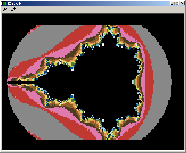
Well, for example, some compiler (or translator) from a high-level language. For example, I tried to write a translator from an Pascal-like language. Of course, something happened, but it is clearly not enough for a full-fledged language. Here such programs could write on it:
var xPixels, yPixels, xStart, yStart, Xsize, YSize, maxiter : integer; xStep, yStep : integer; ix,iy,x,y,x0,y0,iteration,xtemp : integer; dist : byte; temp : byte; xx,yy : byte; begin XPixels := 160; YPixels := 100; XStart := $FF9c; YStart := $FFce; XSize := 160; YSize := 100; MaxIter := 16; XStep := XSize div XPixels; YStep := YSize div YPixels; yy := 20; For iy := 0 to yPixels do begin xx := 0; For ix := 0 to xPixels do begin x := xStart + ix * xStep; y := yStart + iy * yStep; x0 := x; y0 := y; iteration := 0; Repeat xtemp := ((x*x) div 48) - ((y*y) div 48) + x0; y := 2*((x*y) div 48) + y0; x := xtemp; iteration := iteration + 1; dist := ((x*x) div 48) + ((y*y) div 48); If iteration = maxiter then dist := 4000; Until dist > 192; If iteration <> maxiter then If iteration > 1 then begin temp := ((iteration shl 4) or iteration) shl 8; temp := temp or ((iteration shl 4) or iteration); DrawSprite(xx,yy,$0201,^temp); end; xx := xx + 2; end; yy := yy + 2; end; end. The output was a ton of assembler govnokod, which was compiled by the above assembler tchip16. In the end, it somehow worked and gave the following picture:
Unfortunately, I scored, I didn’t have enough skill to bring everything to release or at least beta.
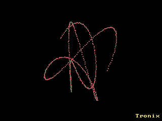
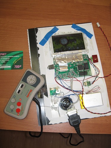
What else ... Oh yes, there was an interesting case - they wanted to stir up the CHIP16 demo component, such as writing demos for a subject. Well, what, old school, resources are limited, this is not a shooter with gigami operatives. In theory, you can completely spin the old effects, as though there is no frame buffer, but there are 32Kb operatives under the sprite the size of the whole screen. And 32Kb per code remains. It will be even without blinking the screen. My small demo sinedots (such points are spinning in space, it turns out to be three-dimensional). The truth is, I stepped here, and I’d output the dots exactly with dots (sprites of one byte) because of what the blink is.You can also create the entire platform in hardware (for fans of FPGAs and other transistors). And I might write my emulator for this piece of iron:
And let it not quite hardware in terms of hardware (there is a normal MIPS processor), but it is still interesting.
Good luck to all!
Source: https://habr.com/ru/post/146496/
All Articles