More about data transmission technology for optics. Wavelength multiplexing of signals
On Habré there are not so many articles devoted to technologies of optical communication lines. Recently, an article appeared on the optical budget , there were articles on high-power DWDM systems , and a brief article on the use of the CWDM system . I will try to supplement these materials and briefly tell you about all the most common and available in Russia ways to use the resource of fiber-optic communication lines in data networks and - quite a bit - cable television.
The most common single-mode optical fiber is SMF G.652 of various modifications. Almost certainly, if you have a fiber optic line, it is made of G.652 fiber. He has a number of important characteristics to keep in mind.
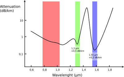
The specific (it is also called kilometric) attenuation - that is, the attenuation of one kilometer of fiber - depends on the radiation wavelength.
Wikipedia tells us the following distribution:
 .
.
')
In real life, the picture is now better, in particular, the specific attenuation in a 1310nm window usually fits into 0.35dB / km, in a 1550nm window it is about 0.22-0.25dB / km, and the so-called “water peak” around 1400-1450nm in modern fibers is not so pronounced or absent altogether.
Nevertheless, one must keep in mind this picture and the very existence of this dependence.
Historically, the wavelength range that is transmitted by optical fiber is divided into the following ranges:
O - 1260 ... 1360
E - 1360 ... 1460
S - 1460 ... 1530
C - 1530 ... 1565
L - 1565 ... 1625
U - 1625 ... 1675
(I quote for the same article on Wikipedia).
With an acceptable approximation, the fiber properties within each range can be considered approximately the same. The water peak usually occurs at the long-wave end of the E-band. We will also keep in mind that the specific (kilometric) attenuation in the O-range is about one and a half times higher than in the S- and C-ranges, specific chromatic dispersion - on the contrary, has a zero minimum at a wavelength of 1310nm and a non-zero in C -range.
Initially, the duplex fiber-optic communication line required two fibers for operation: one fiber transmitted information in one direction, the other fiber - in the other. This is convenient for its obviousness, but rather wasteful in relation to the use of the resource of the laid cable.
Therefore, as soon as the technology began to allow, solutions began to appear for the transfer of information in both directions along a single fiber. The names of such solutions are “single-fiber transceivers”, “WDM”, “bi-directional”.
In the most common variants, wavelengths of 1310 and 1550 nm are used, respectively, from the O- and C-bands. "In the wild" transceivers for these wavelengths are found for lines up to 60km. More “long-range” options are made for other combinations - 1490/1550, 1510/1570 and similar options using transparency windows with a lower specific attenuation than in the O-range.
In addition to the above pairs of wavelengths, it is possible to encounter a combination of 1310 / 1490nm - it is used if a cable television signal is transmitted simultaneously with the data on the same fiber at a wavelength of 1550nm; or 1270 / 1330nm - it is used to transmit 10 Gbit / s streams.
Since I have touched on the topic of KTV, I will talk about it a little more.
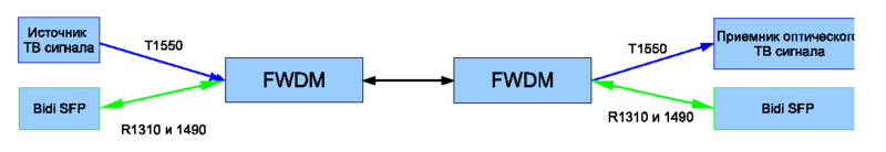
Optics are now also used to deliver cable television signal from the head station to the apartment building. For it, either a wavelength of 1310nm is used - here the minimum chromatic dispersion, that is, signal distortion; or a wavelength of 1550 nm - here the minimum specific attenuation and the use of pure-optical amplification using EDFA is possible. If there is a need for delivery to one house at the same time and the data stream (Internet) and sinal KTV, you must either use two separate fibers, or an uncomplicated passive device - an FWDM filter.
This reversible device (that is, the same device is used both for multiplexing and for demultiplexing streams) with three outputs: for CATV, a single-fiber transceiver, and a common output (see diagram). Thus, it is possible to build a PON or Ethernet network using wavelengths of 1310/1490 for data transmission, and 1550nm for cable TV.
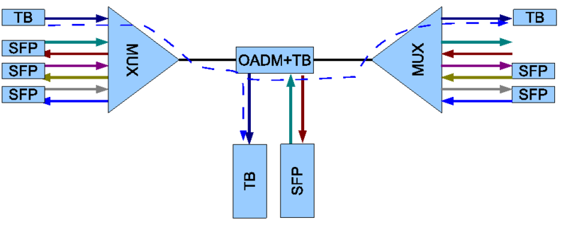
About sealing CWDM already briefly told theslim . From myself I will add only that the channels specified in the article for receiving and transmitting data are pure convention, the multiplayer doesn't care at all which way the signal goes in each channel; and optical receivers are broadband, they respond to radiation of any wavelength. Of the important points to keep in mind when designing a CWDM line is the difference in the specific attenuation in the fiber on different channels (see the first section of this article), as well as the difference in the attenuation introduced by the multiplexer itself. The multiplexer is made of series-connected filters, and if for the first channel in the chain the attenuation can be less than one decibel, then for the latter it will be closer to four (these values are given for the multiplexer 1x16, 16 wavelengths). It is also useful to remember that no one forbids building two-fiber CWDM lines by simply combining two pairs of multiplexers into one functional unit.
In addition, I note that it is quite possible to allocate part of the frequency resource for cable TV, transmitting up to seven duplex data streams over a single fiber simultaneously with analog television.
The DWDM system is fundamentally no different from CWDM, but - as they say - "the devil is in the details." If the channel pitch in CWDM is 20nm, then for DWDM it is much narrower and measured in gigahertz (the most common option now is 100 GHz, or about 0.8 nm; an outdated version with a 200 GHz band is also possible and the more modern 50 and 25 GHz are gradually spreading). The frequency range of DWDM lies in the C-and L-band, 40 channels in 100 GHz each. From this follows several important properties of DWDM systems.
Firstly, they are much more expensive than CWDM. To use them, lasers with a strict wavelength tolerance and multiplexers of very high selectivity are required.
Secondly, the ranges used are in the working areas of EDFA optical amplifiers. This allows you to build long lines with pure optical amplification without the need for opto-electronic signal conversion. It is this property that has led many to immediately imagine the complex systems of monsters of the telecom market at the word “DWDM”, although such equipment can also be used in simpler systems.
And thirdly, the attenuation in the C- and L-bands is minimal from the entire transparency window of the optical fiber, which allows even without amplifiers to build lines of greater length than when using CWDM.
DWDM multiplexers are just as passive devices as CWDM multiplexers. For the number of channels up to 16, they are also made up of separate filters, and these are fairly simple devices. However, multiplexers for more channels are made using Arrayed Wavelength Grating technology , which is extremely sensitive to temperature changes. Therefore, such multiplexers are available either with an electronic thermal stabilization circuit (Thermal AWG) or using special autocompensation methods that do not require energy (Athermal AWG). This makes such multiplexers more expensive and gentle to use.
In conclusion, I will talk a little about the limitations that we have to deal with when organizing communications in optics.
As comrade saul quite rightly pointed out , the first constraint is the optical budget.
I will supplement it with some clarifications.
If we are talking about two-fiber communication lines, it is enough to calculate the optical budget for one wavelength - the one on which the transmission will take place.
As soon as we have a wave compaction (especially in the case of single-fiber transceivers or CWDM systems), we must immediately recall the unevenness of the specific attenuation of the fiber at different wavelengths and the attenuation introduced by the multiplexers.
If we build a system with intermediate branches on the OADM - do not forget to calculate the attenuation on the OADM. By the way, it is different for end-to-end channel and output wavelengths.
Do not forget to leave a few decibels of operating margin.
The second thing to deal with is the chromatic dispersion. It really becomes relevant for 10Gbit / s lines, and generally speaking, the manufacturer of equipment thinks about it first of all. By the way, it is the variance that gives physical meaning to the mentioning of kilometers in the marketing names of transceivers. It is simply useful for an operation specialist to understand that there is such a property of the fiber and that apart from the attenuation of the signal in the fiber, the picture is also spoiled by the dispersion.
For simple systems without amplifiers, the calculation of the line basically boils down to calculating the optical budget, and the topic of calculating the line with amplifiers is well worth a separate article.
Here, in brief, is the engineering basis for compaction technologies in optical lines. I hope this information will be useful to readers; I will be happy to answer your questions.
Start. Properties of standard single mode G.652 fiber
The most common single-mode optical fiber is SMF G.652 of various modifications. Almost certainly, if you have a fiber optic line, it is made of G.652 fiber. He has a number of important characteristics to keep in mind.
The specific (it is also called kilometric) attenuation - that is, the attenuation of one kilometer of fiber - depends on the radiation wavelength.
Wikipedia tells us the following distribution:
.')
In real life, the picture is now better, in particular, the specific attenuation in a 1310nm window usually fits into 0.35dB / km, in a 1550nm window it is about 0.22-0.25dB / km, and the so-called “water peak” around 1400-1450nm in modern fibers is not so pronounced or absent altogether.
Nevertheless, one must keep in mind this picture and the very existence of this dependence.
Historically, the wavelength range that is transmitted by optical fiber is divided into the following ranges:
O - 1260 ... 1360
E - 1360 ... 1460
S - 1460 ... 1530
C - 1530 ... 1565
L - 1565 ... 1625
U - 1625 ... 1675
(I quote for the same article on Wikipedia).
With an acceptable approximation, the fiber properties within each range can be considered approximately the same. The water peak usually occurs at the long-wave end of the E-band. We will also keep in mind that the specific (kilometric) attenuation in the O-range is about one and a half times higher than in the S- and C-ranges, specific chromatic dispersion - on the contrary, has a zero minimum at a wavelength of 1310nm and a non-zero in C -range.
Simplest compaction systems - bidirectional single fiber transmission
Initially, the duplex fiber-optic communication line required two fibers for operation: one fiber transmitted information in one direction, the other fiber - in the other. This is convenient for its obviousness, but rather wasteful in relation to the use of the resource of the laid cable.
Therefore, as soon as the technology began to allow, solutions began to appear for the transfer of information in both directions along a single fiber. The names of such solutions are “single-fiber transceivers”, “WDM”, “bi-directional”.
In the most common variants, wavelengths of 1310 and 1550 nm are used, respectively, from the O- and C-bands. "In the wild" transceivers for these wavelengths are found for lines up to 60km. More “long-range” options are made for other combinations - 1490/1550, 1510/1570 and similar options using transparency windows with a lower specific attenuation than in the O-range.
In addition to the above pairs of wavelengths, it is possible to encounter a combination of 1310 / 1490nm - it is used if a cable television signal is transmitted simultaneously with the data on the same fiber at a wavelength of 1550nm; or 1270 / 1330nm - it is used to transmit 10 Gbit / s streams.
Data and cable TV multiplexing
Since I have touched on the topic of KTV, I will talk about it a little more.
Optics are now also used to deliver cable television signal from the head station to the apartment building. For it, either a wavelength of 1310nm is used - here the minimum chromatic dispersion, that is, signal distortion; or a wavelength of 1550 nm - here the minimum specific attenuation and the use of pure-optical amplification using EDFA is possible. If there is a need for delivery to one house at the same time and the data stream (Internet) and sinal KTV, you must either use two separate fibers, or an uncomplicated passive device - an FWDM filter.
This reversible device (that is, the same device is used both for multiplexing and for demultiplexing streams) with three outputs: for CATV, a single-fiber transceiver, and a common output (see diagram). Thus, it is possible to build a PON or Ethernet network using wavelengths of 1310/1490 for data transmission, and 1550nm for cable TV.
CWDM and DWDM
About sealing CWDM already briefly told theslim . From myself I will add only that the channels specified in the article for receiving and transmitting data are pure convention, the multiplayer doesn't care at all which way the signal goes in each channel; and optical receivers are broadband, they respond to radiation of any wavelength. Of the important points to keep in mind when designing a CWDM line is the difference in the specific attenuation in the fiber on different channels (see the first section of this article), as well as the difference in the attenuation introduced by the multiplexer itself. The multiplexer is made of series-connected filters, and if for the first channel in the chain the attenuation can be less than one decibel, then for the latter it will be closer to four (these values are given for the multiplexer 1x16, 16 wavelengths). It is also useful to remember that no one forbids building two-fiber CWDM lines by simply combining two pairs of multiplexers into one functional unit.
In addition, I note that it is quite possible to allocate part of the frequency resource for cable TV, transmitting up to seven duplex data streams over a single fiber simultaneously with analog television.
The DWDM system is fundamentally no different from CWDM, but - as they say - "the devil is in the details." If the channel pitch in CWDM is 20nm, then for DWDM it is much narrower and measured in gigahertz (the most common option now is 100 GHz, or about 0.8 nm; an outdated version with a 200 GHz band is also possible and the more modern 50 and 25 GHz are gradually spreading). The frequency range of DWDM lies in the C-and L-band, 40 channels in 100 GHz each. From this follows several important properties of DWDM systems.
Firstly, they are much more expensive than CWDM. To use them, lasers with a strict wavelength tolerance and multiplexers of very high selectivity are required.
Secondly, the ranges used are in the working areas of EDFA optical amplifiers. This allows you to build long lines with pure optical amplification without the need for opto-electronic signal conversion. It is this property that has led many to immediately imagine the complex systems of monsters of the telecom market at the word “DWDM”, although such equipment can also be used in simpler systems.
And thirdly, the attenuation in the C- and L-bands is minimal from the entire transparency window of the optical fiber, which allows even without amplifiers to build lines of greater length than when using CWDM.
DWDM multiplexers are just as passive devices as CWDM multiplexers. For the number of channels up to 16, they are also made up of separate filters, and these are fairly simple devices. However, multiplexers for more channels are made using Arrayed Wavelength Grating technology , which is extremely sensitive to temperature changes. Therefore, such multiplexers are available either with an electronic thermal stabilization circuit (Thermal AWG) or using special autocompensation methods that do not require energy (Athermal AWG). This makes such multiplexers more expensive and gentle to use.
Practical limitations in fiber-optic communications
In conclusion, I will talk a little about the limitations that we have to deal with when organizing communications in optics.
As comrade saul quite rightly pointed out , the first constraint is the optical budget.
I will supplement it with some clarifications.
If we are talking about two-fiber communication lines, it is enough to calculate the optical budget for one wavelength - the one on which the transmission will take place.
As soon as we have a wave compaction (especially in the case of single-fiber transceivers or CWDM systems), we must immediately recall the unevenness of the specific attenuation of the fiber at different wavelengths and the attenuation introduced by the multiplexers.
If we build a system with intermediate branches on the OADM - do not forget to calculate the attenuation on the OADM. By the way, it is different for end-to-end channel and output wavelengths.
Do not forget to leave a few decibels of operating margin.
The second thing to deal with is the chromatic dispersion. It really becomes relevant for 10Gbit / s lines, and generally speaking, the manufacturer of equipment thinks about it first of all. By the way, it is the variance that gives physical meaning to the mentioning of kilometers in the marketing names of transceivers. It is simply useful for an operation specialist to understand that there is such a property of the fiber and that apart from the attenuation of the signal in the fiber, the picture is also spoiled by the dispersion.
For simple systems without amplifiers, the calculation of the line basically boils down to calculating the optical budget, and the topic of calculating the line with amplifiers is well worth a separate article.
Here, in brief, is the engineering basis for compaction technologies in optical lines. I hope this information will be useful to readers; I will be happy to answer your questions.
Source: https://habr.com/ru/post/146484/
All Articles