Intellectual SCS. Molex MIIM system
Among specialists in the field of SCS, systems for automatic monitoring of the physical layer of switching are called intelligent SCS. If you use more accessible terms - these are dispatching field switching systems that automatically register all the switching cord connections / disconnections and provide a graphic display of the cross on the system administrator's computer. Under habrakatom review of such a system.

')
Requests for the development of such systems appeared in the operational services of IT departments and manufacturers of SCS components in the mid-1990s. Due to the rapid spread of networks on twisted pair and the emergence of cross with a capacity of hundreds and thousands of ports, cable management "in manual mode" has become a very routine and time-consuming process. Moreover, in our country, taking into account the human factor, real records are kept at best during the first few months after the installation of the cable system. An exception may be companies where a separate engineer is identified for these needs, or the traditions of the Soviet school of communications specialists are observed in the key of pedantic accounting of everything and everyone. But no one wants to single out employees, but traditions are forgotten.
How can you automatically keep track of all changes? How can I determine the connection patch cord plugs to the patch panel ports?
The first way is to use contact-type sensors located in or near the connector, which close when the plug is connected. The event is read by the controller and recorded in its internal memory. After that, the controller through the LAN transmits information to the administrator's computer, where it is processed and displayed in the graphical interface.
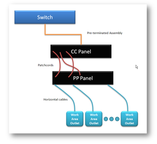
Optimal use of the system involves the use of a cross-connect scheme. Ports of active equipment are intersected on an intermediate patch panel. Those. By analogy with telephony there is a station and subscriber parts of the cross. All switching takes place exclusively on it.
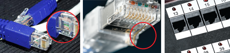
This decision was the basis for the first development of these systems. They were introduced to RIT and iTracs with the only difference that RIT had additional contacts for the sensor circuit integrated directly into the plug connector, and ITracs made a little bit of a side. Additional pins were connected with the ninth conductor, also integrated into the patch cord. Those. With conventional patch cords system can not work.
In the system from RIT, each port was equipped with an LED indicator to highlight the work orders for switching.
Over time, licensed copies of these systems appeared in the main SCS players: AMP Netconnect (currently TE Connectivity), Molex PN, Panduit, etc.
A somewhat similar solution was implemented in the iPatch system from Systimax. There, a photo element is used to register the connection event. This eliminated the need to use specialized patch cords, but made it impossible for the system to automatically detect the port-port connection when it is done in a chaotic manner. In this case, the configuration is adjusted by the administrator after each switch.
In general, these systems allowed to provide:
1. Monitoring of all physical connections on the cross.
2. Alarm on all unauthorized connections / disconnections.
3. Graphic display of the cross on the system administrator's computer.
4. Forming a snapshot of the system and exporting a cable log.
5. LED indications of individual ports (implemented in systems from RIT, Systimax, Panduit) for “highlighting” work orders for switching.
The main disadvantage of these systems is the use of non-standard patch cords, the cost of which far exceeds the cost of ordinary ones.
Molex PN, which initially promoted a licensed copy of the Itracs system under the Molex RealTime trademark, developed and introduced in 2008 a completely new system with a new expanded functionality, a minimum number of components and a new graphical interface.
The system is called MIIM (Molex Intelligent Infrastructure Manager).
The main functions and competitive advantages realized in this system:
1. Using standard patch cords
2. Control of the entire channel, from the switch port to the device network card port at the workplace
3. Continuous monitoring and mapping of physical network connections (Layer 1)
4. Determination of the network device connection to the port of the subscriber outlet, even when it is disconnected from the power source, indicating the physical location
5. Detection of horizontal cable break
6. Determination of IP and MAC addresses connected to the workplace devices
7. Signaling the change in configuration by means of SNMP messages
8. New graphical interface
9. Advanced reporting tools
The system consists of only four components: the MIIM switching panels, the controller, the terminators of the sockets of the subscriber sockets and software.
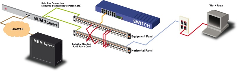
The scheme of the "implementation" of the MIIM system is as follows:
Consider each of the components of the system separately.
MIIM panels are no different from the standard Molex patch panels, except for the presence of an additional RJ45 port (for connection to the analyzer) and port LEDs.
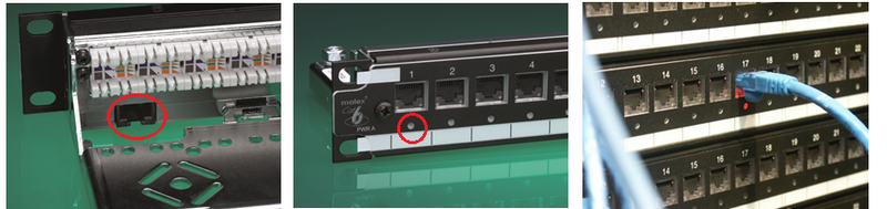
According to the manufacturer, the electronic “filling” of the panel is nothing more than a conventional electrical cable tester. Using the cores of the standard patch cord (roughly speaking, cutting into the channel), the system records changes in the physical characteristics of the ports when the patch cord is connected / disconnected, thereby recording the event.
Each panel is connected to the controller with standard RJ45-RJ45 category 5e patch cord. Panels are not network devices, data transmission is carried out using a specialized protocol. The limit on the length of the patch cord 100m.
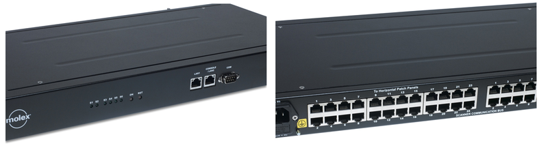
In the MIIM system, the controller is named by the scanner. This device is “19”, 1U high. Power consumption not more than 30W. It is possible to connect 24 panels of the display of ports of the active equipment and 24 panels on which the cables from workplaces are embroidered to one analyzer. Thus, 1 analyzer can control 576 channels using a cross-connect scheme. The number of analyzers in the system is unlimited. The scanner connects to the software server via LAN. The figure shows the front and back of the scanner.

The device is a plastic nozzle on the pins of the subscriber outlet with a special built-in component. The terminator allows you to monitor the integrity of the horizontal SCS cable as well as determine whether any device is connected at the workplace or the port is free. The presence of the terminator allows the MIIM analyzer to monitor the entire stationary line up to the workplace. If you don’t need this functionality, you can stop buying terminators
MIIM software runs on MS Windows 2008 Server platform in conjunction with MS SQL Server 2008. The graphical interface is developed using MS Silver light technology. Thus, a web browser window is used to access the graphical interface.
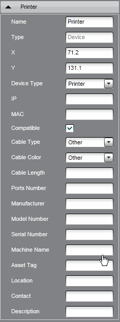
Below is a screenshot of the main window of the system, the so-called working area. On the left is the hierarchical structure of the system objects. It includes: buildings, floors, rooms, wiring closets with equipment, ports of subscriber sockets, network devices (printer, PC, laptop, VoIP phone, etc.). Access to any object and its properties (tabs on the right) takes a matter of seconds.
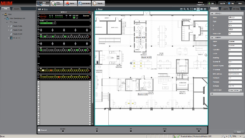
For example, for the subscriber outlet, the port number, the length and type of the horizontal cable, the IP and MAC address of the connected device are indicated (MIIM is put in automatic mode).
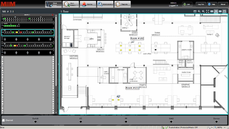
You can minimize the extra bookmarks and work directly with the floor plan, where, in accordance with the project, the ports of subscriber sockets and the switching cabinet “serving” the specified zone are placed.
Depending on the state of connections, each port is filled with one color or another. The table below shows the legend for each of the colors.
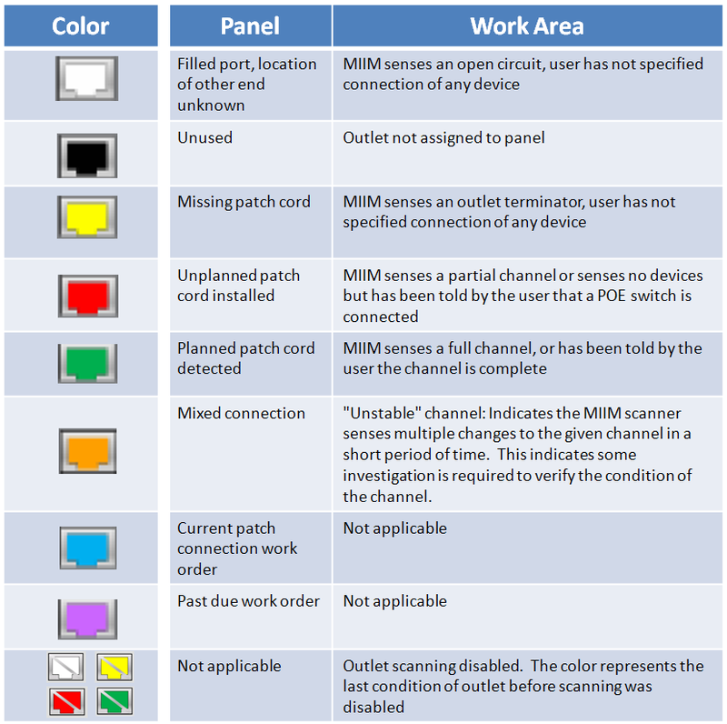
For example, on the ports of the switching panels, green means that the switching is performed in accordance with the specified configuration, yellow indicates an unauthorized disconnection of the patch cord, red, on the contrary, an unauthorized connection.
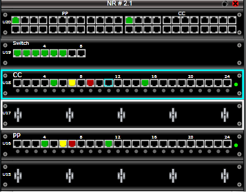
If you want to add / remove a new connection to the configuration, you need to create a so-called work order. To do this, just mark the ports on the panels that need to be switched / reconnected. After that, the system will paint the selected ports in accordance with the legend with a turquoise color, and on the panels themselves in the cabinet light bulbs above the specified ports. After that, you can send to the engineer of the cross, it will be difficult for him to make a mistake. But even if this happens, the system will detect an error, and the lights will remain on until the moment of correct switching.
Separately, I would like to mention that you can bind a network device, such as a printer, to a specific port of the subscriber outlet, setting its data in the properties tab. If you have switches of the 3rd level, then MIIM after simple settings will automatically pull up its IP and MAC address here. And it really works.
On the basis of MIIM you can build an inventory system of all network equipment. Using the stored database of MAC addresses, you can find where a network device is physically located.
The system constantly records all changes. Configuration backup is performed automatically according to the schedule set by the administrator. The backup includes data on the entire structure of the objects of the system, their location (exact binding on the plans) and all the switching on the cross.
SNMP is used to communicate with other network infrastructure management systems. Messages are sent to the IP address specified by the administrator. Using this mechanism, it is possible to implement automatic blocking of ports by the switch when unauthorized connection of the patch cord at the cross-country or at the workplace.
A separate module is responsible for generating reports. The toolkit is quite large. You can create more than 15 report templates and select a schedule for their automatic generation. Reports are saved in PDF format.
In general, the work of software in conjunction with the iron does not cause any complaints. All declared functions work regularly.
The implementation of MIIM for the cable system, which is built from scratch, is not particularly difficult due to the minimum range of components. However, we will have to face a double increase in the number of patch panels for organizing a cross-connect scheme, as well as cross-connect patch cords to connect MIIM panels to switch ports.
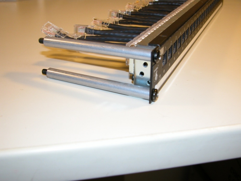
True, at the factory you can order ready-made preterminated panels with cords of a given length. This solution is extremely convenient when upgrading an already functioning SCS. With the help of a special bracket, the existing switching panels are recessed into the rack / cabinet and connected to the MIIM panels. However, this operation takes no more than 5 minutes.

The initial software setup takes 2-3 hours. All the rest of the time it takes to arrange ports on the plans and bind them to the ports of the panels. Depending on the size of the project, this can take from several hours to several days. But given the fact that this work is not highly qualified, anyone who has ever sat at a computer can handle it.
Summing up, I can say that the system is fully operational, but given the additional cost (to the main SCS), it is applicable primarily in high-budget and high-tech projects. Although in the near future, along with an increase in the number of successful implementations, interest from end customers will also grow.
MUK-Service - all types of IT repair: warranty, non-warranty repair, sale of spare parts, contract service
A bit of history
')
Requests for the development of such systems appeared in the operational services of IT departments and manufacturers of SCS components in the mid-1990s. Due to the rapid spread of networks on twisted pair and the emergence of cross with a capacity of hundreds and thousands of ports, cable management "in manual mode" has become a very routine and time-consuming process. Moreover, in our country, taking into account the human factor, real records are kept at best during the first few months after the installation of the cable system. An exception may be companies where a separate engineer is identified for these needs, or the traditions of the Soviet school of communications specialists are observed in the key of pedantic accounting of everything and everyone. But no one wants to single out employees, but traditions are forgotten.
How can you automatically keep track of all changes? How can I determine the connection patch cord plugs to the patch panel ports?
The first way is to use contact-type sensors located in or near the connector, which close when the plug is connected. The event is read by the controller and recorded in its internal memory. After that, the controller through the LAN transmits information to the administrator's computer, where it is processed and displayed in the graphical interface.
Optimal use of the system involves the use of a cross-connect scheme. Ports of active equipment are intersected on an intermediate patch panel. Those. By analogy with telephony there is a station and subscriber parts of the cross. All switching takes place exclusively on it.
This decision was the basis for the first development of these systems. They were introduced to RIT and iTracs with the only difference that RIT had additional contacts for the sensor circuit integrated directly into the plug connector, and ITracs made a little bit of a side. Additional pins were connected with the ninth conductor, also integrated into the patch cord. Those. With conventional patch cords system can not work.
In the system from RIT, each port was equipped with an LED indicator to highlight the work orders for switching.
Over time, licensed copies of these systems appeared in the main SCS players: AMP Netconnect (currently TE Connectivity), Molex PN, Panduit, etc.
A somewhat similar solution was implemented in the iPatch system from Systimax. There, a photo element is used to register the connection event. This eliminated the need to use specialized patch cords, but made it impossible for the system to automatically detect the port-port connection when it is done in a chaotic manner. In this case, the configuration is adjusted by the administrator after each switch.
In general, these systems allowed to provide:
1. Monitoring of all physical connections on the cross.
2. Alarm on all unauthorized connections / disconnections.
3. Graphic display of the cross on the system administrator's computer.
4. Forming a snapshot of the system and exporting a cable log.
5. LED indications of individual ports (implemented in systems from RIT, Systimax, Panduit) for “highlighting” work orders for switching.
The main disadvantage of these systems is the use of non-standard patch cords, the cost of which far exceeds the cost of ordinary ones.
Molex PN, which initially promoted a licensed copy of the Itracs system under the Molex RealTime trademark, developed and introduced in 2008 a completely new system with a new expanded functionality, a minimum number of components and a new graphical interface.
The system is called MIIM (Molex Intelligent Infrastructure Manager).
The main functions and competitive advantages realized in this system:
1. Using standard patch cords
2. Control of the entire channel, from the switch port to the device network card port at the workplace
3. Continuous monitoring and mapping of physical network connections (Layer 1)
4. Determination of the network device connection to the port of the subscriber outlet, even when it is disconnected from the power source, indicating the physical location
5. Detection of horizontal cable break
6. Determination of IP and MAC addresses connected to the workplace devices
7. Signaling the change in configuration by means of SNMP messages
8. New graphical interface
9. Advanced reporting tools
The system consists of only four components: the MIIM switching panels, the controller, the terminators of the sockets of the subscriber sockets and software.
The scheme of the "implementation" of the MIIM system is as follows:
Consider each of the components of the system separately.
1. MIIM Patch Panels
MIIM panels are no different from the standard Molex patch panels, except for the presence of an additional RJ45 port (for connection to the analyzer) and port LEDs.
According to the manufacturer, the electronic “filling” of the panel is nothing more than a conventional electrical cable tester. Using the cores of the standard patch cord (roughly speaking, cutting into the channel), the system records changes in the physical characteristics of the ports when the patch cord is connected / disconnected, thereby recording the event.
Each panel is connected to the controller with standard RJ45-RJ45 category 5e patch cord. Panels are not network devices, data transmission is carried out using a specialized protocol. The limit on the length of the patch cord 100m.
2. Controller
In the MIIM system, the controller is named by the scanner. This device is “19”, 1U high. Power consumption not more than 30W. It is possible to connect 24 panels of the display of ports of the active equipment and 24 panels on which the cables from workplaces are embroidered to one analyzer. Thus, 1 analyzer can control 576 channels using a cross-connect scheme. The number of analyzers in the system is unlimited. The scanner connects to the software server via LAN. The figure shows the front and back of the scanner.
3. MIIM terminator exit
The device is a plastic nozzle on the pins of the subscriber outlet with a special built-in component. The terminator allows you to monitor the integrity of the horizontal SCS cable as well as determine whether any device is connected at the workplace or the port is free. The presence of the terminator allows the MIIM analyzer to monitor the entire stationary line up to the workplace. If you don’t need this functionality, you can stop buying terminators
4. Software
MIIM software runs on MS Windows 2008 Server platform in conjunction with MS SQL Server 2008. The graphical interface is developed using MS Silver light technology. Thus, a web browser window is used to access the graphical interface.
Below is a screenshot of the main window of the system, the so-called working area. On the left is the hierarchical structure of the system objects. It includes: buildings, floors, rooms, wiring closets with equipment, ports of subscriber sockets, network devices (printer, PC, laptop, VoIP phone, etc.). Access to any object and its properties (tabs on the right) takes a matter of seconds.
For example, for the subscriber outlet, the port number, the length and type of the horizontal cable, the IP and MAC address of the connected device are indicated (MIIM is put in automatic mode).
You can minimize the extra bookmarks and work directly with the floor plan, where, in accordance with the project, the ports of subscriber sockets and the switching cabinet “serving” the specified zone are placed.
Depending on the state of connections, each port is filled with one color or another. The table below shows the legend for each of the colors.
For example, on the ports of the switching panels, green means that the switching is performed in accordance with the specified configuration, yellow indicates an unauthorized disconnection of the patch cord, red, on the contrary, an unauthorized connection.
If you want to add / remove a new connection to the configuration, you need to create a so-called work order. To do this, just mark the ports on the panels that need to be switched / reconnected. After that, the system will paint the selected ports in accordance with the legend with a turquoise color, and on the panels themselves in the cabinet light bulbs above the specified ports. After that, you can send to the engineer of the cross, it will be difficult for him to make a mistake. But even if this happens, the system will detect an error, and the lights will remain on until the moment of correct switching.
Separately, I would like to mention that you can bind a network device, such as a printer, to a specific port of the subscriber outlet, setting its data in the properties tab. If you have switches of the 3rd level, then MIIM after simple settings will automatically pull up its IP and MAC address here. And it really works.
On the basis of MIIM you can build an inventory system of all network equipment. Using the stored database of MAC addresses, you can find where a network device is physically located.
The system constantly records all changes. Configuration backup is performed automatically according to the schedule set by the administrator. The backup includes data on the entire structure of the objects of the system, their location (exact binding on the plans) and all the switching on the cross.
SNMP is used to communicate with other network infrastructure management systems. Messages are sent to the IP address specified by the administrator. Using this mechanism, it is possible to implement automatic blocking of ports by the switch when unauthorized connection of the patch cord at the cross-country or at the workplace.
A separate module is responsible for generating reports. The toolkit is quite large. You can create more than 15 report templates and select a schedule for their automatic generation. Reports are saved in PDF format.
In general, the work of software in conjunction with the iron does not cause any complaints. All declared functions work regularly.
The implementation of MIIM for the cable system, which is built from scratch, is not particularly difficult due to the minimum range of components. However, we will have to face a double increase in the number of patch panels for organizing a cross-connect scheme, as well as cross-connect patch cords to connect MIIM panels to switch ports.
True, at the factory you can order ready-made preterminated panels with cords of a given length. This solution is extremely convenient when upgrading an already functioning SCS. With the help of a special bracket, the existing switching panels are recessed into the rack / cabinet and connected to the MIIM panels. However, this operation takes no more than 5 minutes.
The initial software setup takes 2-3 hours. All the rest of the time it takes to arrange ports on the plans and bind them to the ports of the panels. Depending on the size of the project, this can take from several hours to several days. But given the fact that this work is not highly qualified, anyone who has ever sat at a computer can handle it.
Summing up, I can say that the system is fully operational, but given the additional cost (to the main SCS), it is applicable primarily in high-budget and high-tech projects. Although in the near future, along with an increase in the number of successful implementations, interest from end customers will also grow.
MUK-Service - all types of IT repair: warranty, non-warranty repair, sale of spare parts, contract service
Source: https://habr.com/ru/post/146199/
All Articles