Meet FreeCAD
FreeCAD is a parametric three-dimensional editor that allows you to create three-dimensional models and drawings of their projections.
The current version of FreeCAD is 0.12, but you can also download the beta version 0.13 and try to compile it.
FreeCAD supports several different document formats for both import and export, and also allows you to save "screenshots" (including in pdf format).
Documentation for FreeCAD is quite abundant, but still not as complete as you would like. Questions about using this product can be discussed on the FreeCAD forum .
')
For ease of drawing, FreeCAD has the ability to write scripts on python, and for small operations you can use the python console. The console, however, is elementary: it has no command history.
I will not rewrite the multi-volume FreeCAD user guide, but simply give an example of what can be done with it.
But first, let me explain how to force FreeCAD to “see” your scripts. Before each launch, FreeCAD looks at the contents of the system directories, as well as the ~ / .FreeCAD / Mod / directories. He will use the scripts there in the future.
The scripts in FreeCAD are divided into two categories: scripts called from the command line (to start, you must first load the module containing the python with the import command), as well as scripts launched from the GUI. You can always reload the first with the reload command, but to reboot the second (if you made any changes to the sources), you will need to restart FreeCAD. First consider the work with the first.
Create a sketch in the XY-plane and draw the profile of the “half” of our wheel on it.
To do this, first "by eye" draw the basic shapes in the form of a broken line.
Next, in the right places cut the chamfer (tool «fillet»). And after that - we will place the bindings of points. We will tie the starting points absolutely. Parallel objects will be limited by parallelism, we will set the distances between the parts of the profile and the curvature radii.
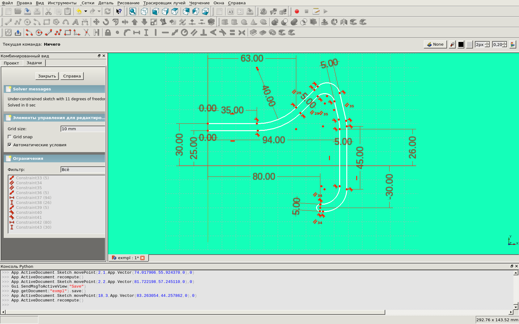
Then we finish editing the sketch, select it in the list of objects (on the left) and click the "rotate the selected sketch" button. We get the following wheel:
Now we will create notches in the “disk”. To do this, we make another sketch in the XZ plane. In it we make a cut of segments and arcs. To make our hole exactly symmetrical about the center, let's bind to two invisible lines.

Let's extend our sketch to 100 units (so that it will most certainly cross the wheel) and move it (Plasement.Position) 50 units along the Y axis:

Now we need to "multiply" the resulting shape around the circumference, then to make cuts in the "wheel". For "reproduction" we will write the NCopy.py script:
Save it in any subdirectory of ~ / .FreeCAD / Mod /.
The CopyObj function has an auxiliary value (it will be useful to us later): this function simply creates a copy of this object.
The copyCirc function has six arguments, all of which are assigned default values, so you can only call it by specifying arguments that have different values. Her arguments are:
We do not need the radius of the circle - we consider the distance from the object to the center of the circle. Object [s] to copy ber [e | y] from selection. If nothing is selected, simply issue the error text and terminate the function. Next, we create the “CircularCopy” group as a function and begin to iterate over all the objects from the selection. Each of them (N-1) is copied around the circle, and then placed in a group.
Now let's estimate: the normal to the circle, along which it is necessary to “multiply” objects, has a value (0.1.0), make the angle between copies equal to 30 degrees, the center is located by default (at the origin), fill the entire circle. So we need to give commands
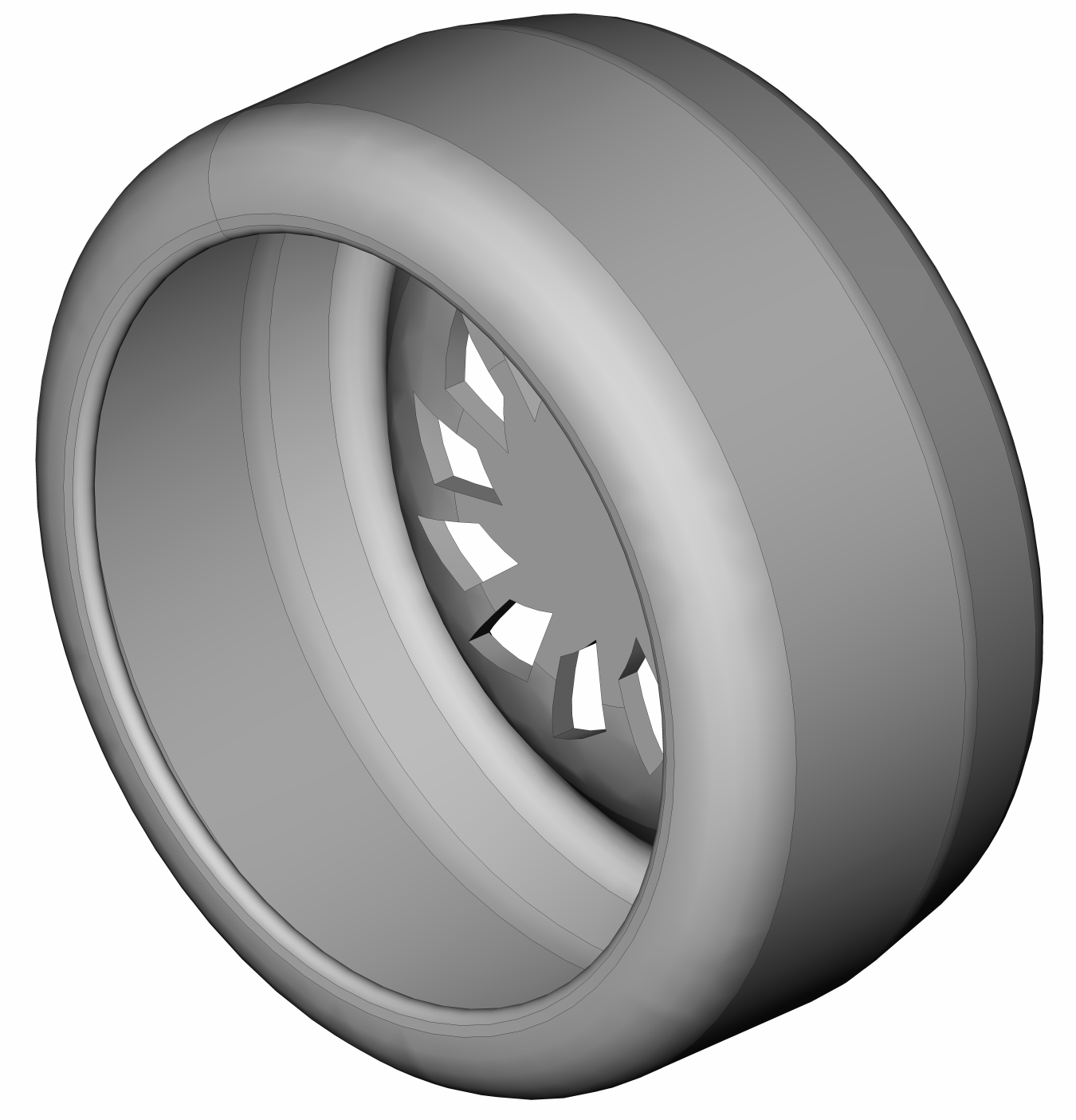
Open the “CircularCopy” group that appears, select all the objects in it and execute their union, the “Fusion” object will appear. Now select our “wheel” (“Revolution”) and this union by pressing the Ctrl key, and select the “intersection” operation. As a result, cuts will appear in our “wheel”:
And this is how the “wheel” exported in pdf will look like:
I will add some more functions for copying objects.
Copying an object to a specified location (mv is the displacement vector, ax is the axis of rotation, rot is the angle of rotation):
Copy N times to vector V:
Copying N times along the path - B-spline:
Now, like a “wheel”, we can draw a simple bearing without a separator.
To begin with we will draw shells. Again, “on the eye” we first draw the outlines of broken lines, then draw a circle between them, which we will immediately make inactive. Next, we will impose restrictions on our figures: the positions of the points, the verticality and horizontality of the sections, the equality of identical lines, the tangential restriction of one point of the furrow in the shells and the surface of the ball, we will introduce some dimensions. As a result, we get the following sketch:

Let's exit the sketch editing mode, select it on the general view and activate the sketch rotation operation. As a result, we get this nice thing:

Now we need to add balls. To do this, activate the “Draw Sphere” icon to get the default sphere. Select it and correct the parameters: make the radius equal to 15 units, and in the position (Placement.Position) make the X coordinate equal to 58 units. In order to “propagate” the balls, we still need to calculate the angular diameter of one ball. The easiest way to do this is to open our sketch again (now it belongs to the “Revolution” object). To prevent the shell from interfering, select it and press the spacebar - it will become invisible. Now draw a segment from the origin to our ball. Let's make restrictions: we will tie one end of the segment strictly to the origin of coordinates, and the second we will make a tangent to the ball. Selecting this segment, we activate the angle limit (of course, FreeCAD will swear on an excessive amount of restrictions, but we only need to look). So, this angle is 14.9882 degrees, roughly speaking - 15 degrees. Immediately remove this restriction so that FreeCAD does not swear and return toour sheep a general view. Select the ball and distribute copies of it around the circle every 30 degrees. By luck, we will need to enter commands similar to the previous item:
Now let's color our objects a bit. To make it easier to paint the balls, combine them into one object. For “beauty”, change the style of displaying objects from “Flat Lines” to “Shaded”. I made the color of the balls “gold” (255, 214, 0), and the color of the shell - “silver” (192, 192, 192). You can change the color not through the GUI, but on the command line (only the RGB components must be normalized by one). If the document is called “bearing,” it will look like this:
Similarly, you can change the type of display:

And you can make a drawing and export it to SVG:

As I have already said, in order to make it possible to launch your commands from the FreeCAD console, you only need to place the files (python modules) with these commands in the ~ / .FreeCAD / Mod / directory or its subdirectories. However, to make it possible to launch commands from the GUI (“buttons”, “menus”, etc.), you need to do a little more.
First, you need to create an initiation script InitGui.py and place it in a script subdirectory. This FreeCAD script will launch when viewing the contents of our script directory.
The minimum content of this file is:
"Lists of items" list contain string variables - the names of the classes provided by our toolkit. Accordingly, for each line of these lists, we must create a corresponding command or class. When you activate a thumbnail on the taskbar or menu item, the designer of this class will be launched, performing some action. The minimum content of this class is:
The last line tells FreeCAD that our OneAction class will correspond to the line “Item name” (accordingly, we will put this line in the lists of the initializer class of our toolkit).
In order to create new objects, we need to create a separate class for these objects. The minimum content of this class is:
The provider class provides the GUI with resources (icons, etc.).
Examples of scripts can be viewed in the FreeCAD resource directories and in the official documentation.
Finally, I will give examples. The first example is drawn without using the command console:

The second example is with simple scripts that allow you to draw lenses. That's where, as they say, "it is better to lose a day, but then in an hour to fly." Here is the code:
allows you to get this:

In the video you can see how this model looks.
Interested advise to go here and see more many different examples.
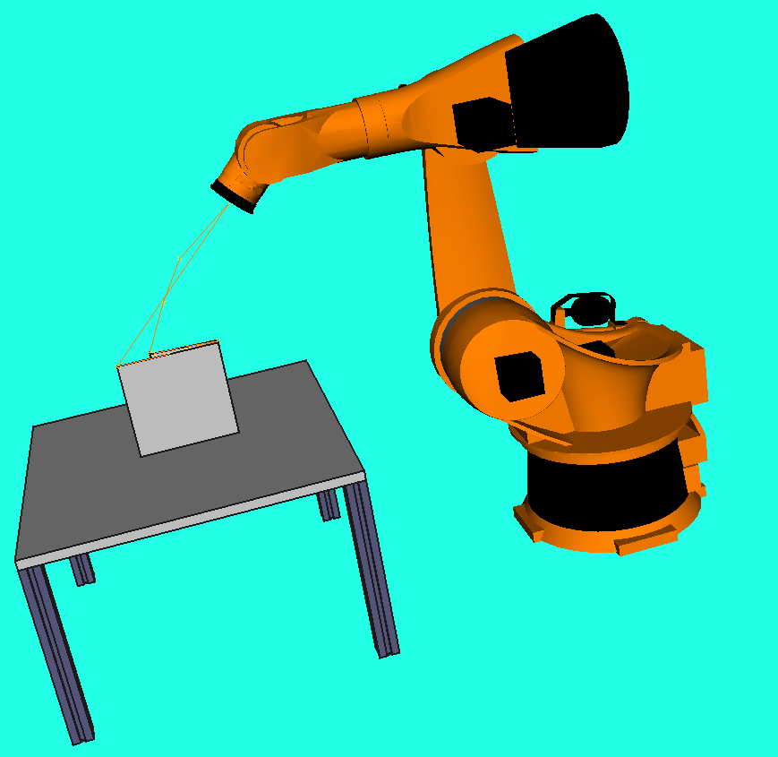
UPD: here is an example of real work performed in a fricade (cryostat).
The current version of FreeCAD is 0.12, but you can also download the beta version 0.13 and try to compile it.
FreeCAD supports several different document formats for both import and export, and also allows you to save "screenshots" (including in pdf format).
Documentation for FreeCAD is quite abundant, but still not as complete as you would like. Questions about using this product can be discussed on the FreeCAD forum .
')
For ease of drawing, FreeCAD has the ability to write scripts on python, and for small operations you can use the python console. The console, however, is elementary: it has no command history.
I will not rewrite the multi-volume FreeCAD user guide, but simply give an example of what can be done with it.
But first, let me explain how to force FreeCAD to “see” your scripts. Before each launch, FreeCAD looks at the contents of the system directories, as well as the ~ / .FreeCAD / Mod / directories. He will use the scripts there in the future.
The scripts in FreeCAD are divided into two categories: scripts called from the command line (to start, you must first load the module containing the python with the import command), as well as scripts launched from the GUI. You can always reload the first with the reload command, but to reboot the second (if you made any changes to the sources), you will need to restart FreeCAD. First consider the work with the first.
Draw the "wheel"
Create a sketch in the XY-plane and draw the profile of the “half” of our wheel on it.
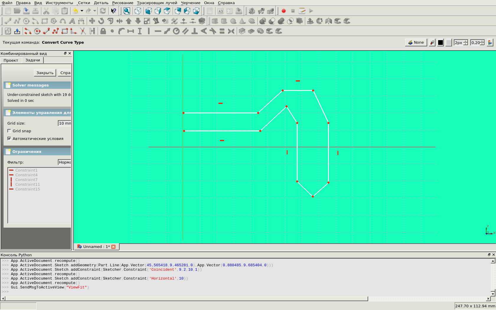
To do this, first "by eye" draw the basic shapes in the form of a broken line.
Next, in the right places cut the chamfer (tool «fillet»). And after that - we will place the bindings of points. We will tie the starting points absolutely. Parallel objects will be limited by parallelism, we will set the distances between the parts of the profile and the curvature radii.
Then we finish editing the sketch, select it in the list of objects (on the left) and click the "rotate the selected sketch" button. We get the following wheel:
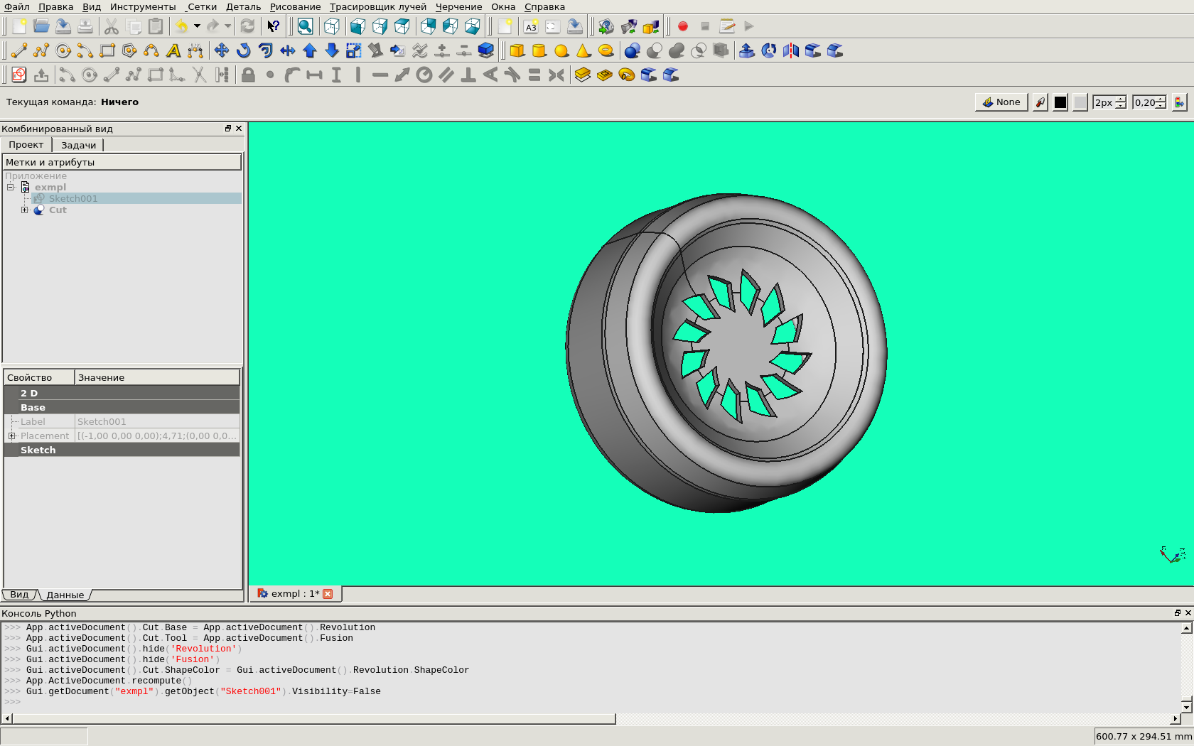
Now we will create notches in the “disk”. To do this, we make another sketch in the XZ plane. In it we make a cut of segments and arcs. To make our hole exactly symmetrical about the center, let's bind to two invisible lines.
Let's extend our sketch to 100 units (so that it will most certainly cross the wheel) and move it (Plasement.Position) 50 units along the Y axis:
Now we need to "multiply" the resulting shape around the circumference, then to make cuts in the "wheel". For "reproduction" we will write the NCopy.py script:
import FreeCAD, FreeCADGui, Part from FreeCAD import Base def CopyObj(obj): name = obj.Name shape = obj.Shape newshape = shape.copy() newobject = FreeCAD.ActiveDocument.addObject("Part::Feature",name) newobject.Shape = newshape return newobject def copyCirc(C=Base.Vector(0,0,0), A=Base.Vector(0,0,1), Ang=90, N=4, rot=True, moveOriToGrp=False): Ang %= 360 if (N > 360/Ang or N == 0): N = int(360/Ang) sel = FreeCADGui.Selection.getSelection() if (not sel): FreeCAD.Console.PrintError("Error: you should select some objects") return None doc = FreeCAD.activeDocument() grp = doc.addObject("App::DocumentObjectGroup", "CircularCopy") for Obj in sel: A0 = Ang for i in range (1, N): newobject = CopyObj(Obj) S = newobject.Shape S.rotate(C, A, A0) if (not rot): S.rotate(S.Placement.Base, A, -A0) grp.addObject(newobject) A0 += Ang if (moveOriToGrp): grp.addObject(Obj) return grp Save it in any subdirectory of ~ / .FreeCAD / Mod /.
The CopyObj function has an auxiliary value (it will be useful to us later): this function simply creates a copy of this object.
The copyCirc function has six arguments, all of which are assigned default values, so you can only call it by specifying arguments that have different values. Her arguments are:
- C - coordinates of the center of the circle on which the copying takes place;
- A is the normal to the plane of the circle;
- Ang is the angle between the copies;
- N - the number of copies (0 - if you need to place objects around the entire circle);
- rot - whether the object itself rotates when copying: if this parameter is False, the object will be distributed around the circle by parallel translation, and not by rotation;
- moveOriToGrp - whether to place the copied original in the general group of created objects.
We do not need the radius of the circle - we consider the distance from the object to the center of the circle. Object [s] to copy ber [e | y] from selection. If nothing is selected, simply issue the error text and terminate the function. Next, we create the “CircularCopy” group as a function and begin to iterate over all the objects from the selection. Each of them (N-1) is copied around the circle, and then placed in a group.
Now let's estimate: the normal to the circle, along which it is necessary to “multiply” objects, has a value (0.1.0), make the angle between copies equal to 30 degrees, the center is located by default (at the origin), fill the entire circle. So we need to give commands
import NCopy NCopy.copyCirc(A=App.Vector(0,1,0), N=0, Ang=30, moveOriToGrp=True) Open the “CircularCopy” group that appears, select all the objects in it and execute their union, the “Fusion” object will appear. Now select our “wheel” (“Revolution”) and this union by pressing the Ctrl key, and select the “intersection” operation. As a result, cuts will appear in our “wheel”:
And this is how the “wheel” exported in pdf will look like:
miscellanea
I will add some more functions for copying objects.
Copying an object to a specified location (mv is the displacement vector, ax is the axis of rotation, rot is the angle of rotation):
def CopyObjAt(obj, mv=Base.Vector(0,0,0), axe=Base.Vector(0,0,0), rot=0): obj = CopyObj(obj) obj.Placement = FreeCAD.Placement(mv, axe, rot) return obj Copy N times to vector V:
def copyVec(N=2, V=Base.Vector(0,0,1), moveOriToGrp=False): sel = FreeCADGui.Selection.getSelection() if sel: doc = FreeCAD.activeDocument() grp = doc.addObject("App::DocumentObjectGroup", "VectorCopy") for Obj in sel: R0 = V for i in range (1, N): newobject = CopyObj(Obj) newobject.Shape.translate(R0) grp.addObject(newobject) R0 += V if (moveOriToGrp): grp.addObject(Obj) else: FreeCAD.Console.PrintError("Error: you should select some objects") return grp Copying N times along the path - B-spline:
def copyByTrajectory(N=4): sel = FreeCADGui.Selection.getSelection() def prErr(): FreeCAD.Console.PrintError("Error: you should select a traectory and one object\n") if (not sel): prErr(); return None L = len(sel) if(L != 2): prErr(); return None if(N < 2): FreeCAD.Console.PrintError("Error: N shold be more than 1\n"); return None Traj = sel[0].Shape #(a, b) = Traj.ParameterRange Obj = sel[1] TLen = Traj.Length / (N - 1) curPos = 0 doc = FreeCAD.activeDocument() grp = doc.addObject("App::DocumentObjectGroup", "BSplineCopy") try: for i in range(0, N): v = Traj.valueAt(curPos); curPos += TLen newobj = CopyObjAt(Obj, v) grp.addObject(newobj) except: FreeCAD.Console.PrintError("Error: bad selection\n") return None We draw the bearing
Now, like a “wheel”, we can draw a simple bearing without a separator.
To begin with we will draw shells. Again, “on the eye” we first draw the outlines of broken lines, then draw a circle between them, which we will immediately make inactive. Next, we will impose restrictions on our figures: the positions of the points, the verticality and horizontality of the sections, the equality of identical lines, the tangential restriction of one point of the furrow in the shells and the surface of the ball, we will introduce some dimensions. As a result, we get the following sketch:
Let's exit the sketch editing mode, select it on the general view and activate the sketch rotation operation. As a result, we get this nice thing:
Now we need to add balls. To do this, activate the “Draw Sphere” icon to get the default sphere. Select it and correct the parameters: make the radius equal to 15 units, and in the position (Placement.Position) make the X coordinate equal to 58 units. In order to “propagate” the balls, we still need to calculate the angular diameter of one ball. The easiest way to do this is to open our sketch again (now it belongs to the “Revolution” object). To prevent the shell from interfering, select it and press the spacebar - it will become invisible. Now draw a segment from the origin to our ball. Let's make restrictions: we will tie one end of the segment strictly to the origin of coordinates, and the second we will make a tangent to the ball. Selecting this segment, we activate the angle limit (of course, FreeCAD will swear on an excessive amount of restrictions, but we only need to look). So, this angle is 14.9882 degrees, roughly speaking - 15 degrees. Immediately remove this restriction so that FreeCAD does not swear and return to
import NCopy NCopy.copyCirc(A=App.Vector(0,1,0), N=0, Ang=30, moveOriToGrp=True) Now let's color our objects a bit. To make it easier to paint the balls, combine them into one object. For “beauty”, change the style of displaying objects from “Flat Lines” to “Shaded”. I made the color of the balls “gold” (255, 214, 0), and the color of the shell - “silver” (192, 192, 192). You can change the color not through the GUI, but on the command line (only the RGB components must be normalized by one). If the document is called “bearing,” it will look like this:
FreeCADGui.getDocument("bearing").getObject("Fusion").ShapeColor = (1.00,0.84,0.00) FreeCADGui.getDocument("bearing").getObject("Revolution").ShapeColor = (0.75,0.75,0.75) Similarly, you can change the type of display:
FreeCADGui.getDocument("bearing").getObject("Revolution").DisplayMode = "Shaded" FreeCADGui.getDocument("bearing").getObject("Fusion").DisplayMode = "Shaded" And you can make a drawing and export it to SVG:
More about script writing
As I have already said, in order to make it possible to launch your commands from the FreeCAD console, you only need to place the files (python modules) with these commands in the ~ / .FreeCAD / Mod / directory or its subdirectories. However, to make it possible to launch commands from the GUI (“buttons”, “menus”, etc.), you need to do a little more.
First, you need to create an initiation script InitGui.py and place it in a script subdirectory. This FreeCAD script will launch when viewing the contents of our script directory.
The minimum content of this file is:
class MyWorkbench ( Workbench ): import Icon = () MenuText = " " ToolTip = " " def Initialize(self): # ToolBar list = [ ] self.appendToolbar(" ",list) # Menu list = [ ] self.appendMenu(" ",list) Gui.addWorkbench(MyWorkbench()) "Lists of items" list contain string variables - the names of the classes provided by our toolkit. Accordingly, for each line of these lists, we must create a corresponding command or class. When you activate a thumbnail on the taskbar or menu item, the designer of this class will be launched, performing some action. The minimum content of this class is:
class OneAction: def Activated(self): #Initialize import , def GetResources(self): import IconPath = ( ) MenuText = " " ToolTip = "" return {'Pixmap' : IconPath, 'MenuText': MenuText, 'ToolTip': ToolTip} FreeCADGui.addCommand(' ', OneAction()) The last line tells FreeCAD that our OneAction class will correspond to the line “Item name” (accordingly, we will put this line in the lists of the initializer class of our toolkit).
In order to create new objects, we need to create a separate class for these objects. The minimum content of this class is:
class MyObject: def __init__(self, obj, ): ''' Add new properties to partfeature ''' obj.addProperty(" "," ","","").= obj.Proxy = self obj.Shape = -(obj.ViewObject) def onChanged(self, obj, prop): , prop, obj - -(obj.ViewObject) def execute(self, obj): , "" -(obj.ViewObject) The provider class provides the GUI with resources (icons, etc.).
Examples of scripts can be viewed in the FreeCAD resource directories and in the official documentation.
Finally, I will give examples. The first example is drawn without using the command console:
The second example is with simple scripts that allow you to draw lenses. That's where, as they say, "it is better to lose a day, but then in an hour to fly." Here is the code:
import Lens a=[[8,6,1,6,3], [10,-15,2.5,8,5], [-16,10,0.5,6,7], [-8,-6,0.5,4,3], [3,3,0.2,2,1], [0,0,0.1,1,0.1], [0,3,.3,1]] Lens.makeLensBench(a) b=[[-10,8,0.1,6], [8,16,0.5,6], [16,-9,1,6]] Lens.makeLensBench(b,App.Vector(0,10,0)) allows you to get this:
In the video you can see how this model looks.
Interested advise to go here and see more many different examples.
UPD: here is an example of real work performed in a fricade (cryostat).
Source: https://habr.com/ru/post/145985/
All Articles