Compensation angle demolition platform aerial camera
Hello! Today I will talk about how I helped my surveyors and aerial photo surveyors not so long ago. My friends are engaged, in simple terms, shooting the Earth from the aircraft, for this they have some equipment and software, and some of it would like them to improve. This year the idea arose to create a software module for automatic compensation of the angle of demolition of the platform on which the aerial camera was installed. Previously, this was done in some manual mode (the platform is very old); calculating the drift angle, it was possible to make an amendment to the platform through some device. The problem was in the calculation and further compensation of this angle ... in fact, if the interest in this article has not disappeared, then I ask for the cut (carefully 7 MB gif'ok) ...
The angle of demolition is the angle between the axis of the aircraft and the coordinate route along which the aircraft flies; it occurs due to weather conditions, namely wind.
For example, when ideal conditions exist, aerial photography proceeds in a similar way:
But such conditions are of course extremely rare, usually the wind speed at an altitude of 10 to 20 km / h and schematically aerial photography will look like this:

That is, the plane seems to resist the force of the wind in order to fly clearly along a given route.
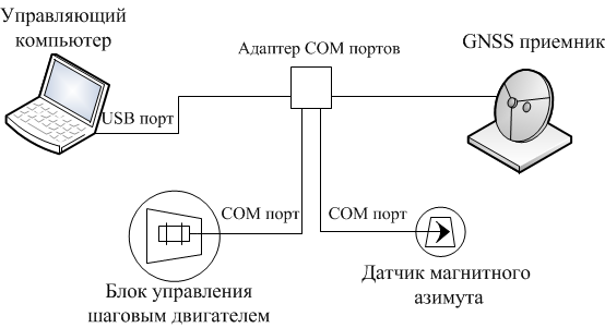
To solve this problem I was provided with the following equipment:
• Magnetic azimuth sensor, more simply - a compass.
• And the control unit of the stepping motor paired with the stepping motor itself.
The software implementation was decided to do on the .Net Framework platform.
Wiring diagram of equipment to the control computer:
To solve the problem in a first approximation, the KVH Azimuth 1000 digital compass with a built-in sensor was selected, its main useful function is to transmit data in NMEA 0183 format using the parallel port protocol.

I previously covered this transmission format in my articles on data emulation from a navigation receiver. In the case of azimuth data from the sensor, a line comes in which you can find the angle value (data refresh rate is 10 Hz, which is quite enough for the implementation of the compensation task). Detailed specifications:
Due to the fact that the data were transmitted in NMEA format, and with it I had previously worked, a module on .Net was written to receive this data.
')
Implementing a stepping motor control system from scratch is too expensive, especially since there are domestic manufacturers providing control units that are programmed controllers that can convert more understandable commands into a control signal for a stepping motor. Commands are transmitted via the parallel port protocol.
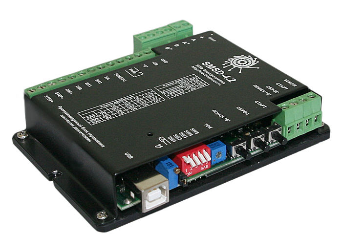
SMSD-4.2 was chosen, it can work autonomously, from a computer (LPT port or USB port) or from an external master controller.
Functions and features of the device:
Specifications:
To implement the module of interaction with the stepper motor control unit, the commands and their order of execution were studied. Commands are mini programs:
The module of work with the control unit was implemented, with the help of it you can set only the angle, if speed is required (if not specified, then the most optimal speed is chosen) and direction.
And as a result, combining the above solutions was created module for automatic compensation of the angle of demolition. Below the demo video , it shows how the platform is compensated at a given angle when the magnetic azimuth changes.
And this is how the process of aerial photography with automatic compensation of the angle of demolition will look like.

I hope that it was not for nothing that I spent the minutes reading my articles, waiting for feedback ...
Introduction
The angle of demolition is the angle between the axis of the aircraft and the coordinate route along which the aircraft flies; it occurs due to weather conditions, namely wind.
For example, when ideal conditions exist, aerial photography proceeds in a similar way:
But such conditions are of course extremely rare, usually the wind speed at an altitude of 10 to 20 km / h and schematically aerial photography will look like this:
That is, the plane seems to resist the force of the wind in order to fly clearly along a given route.
To solve this problem I was provided with the following equipment:
• Magnetic azimuth sensor, more simply - a compass.
• And the control unit of the stepping motor paired with the stepping motor itself.
The software implementation was decided to do on the .Net Framework platform.
Wiring diagram of equipment to the control computer:
Magnetic azimuth sensor
To solve the problem in a first approximation, the KVH Azimuth 1000 digital compass with a built-in sensor was selected, its main useful function is to transmit data in NMEA 0183 format using the parallel port protocol.
I previously covered this transmission format in my articles on data emulation from a navigation receiver. In the case of azimuth data from the sensor, a line comes in which you can find the angle value (data refresh rate is 10 Hz, which is quite enough for the implementation of the compensation task). Detailed specifications:
- ± 0.5 ° accuracy with autocompensation;
- diameter 16 cm;
- height 7 cm;
- sensitivity to a field of 6.5–65 μT;
- weight 340 g;
- cable length 2 m;
- operating temperature range from -20 to 70 ° C;
- frequency data in NMEA 0183 10 Hz;
- supply voltage 12 V.
Due to the fact that the data were transmitted in NMEA format, and with it I had previously worked, a module on .Net was written to receive this data.
')
Stepper motor control unit
Implementing a stepping motor control system from scratch is too expensive, especially since there are domestic manufacturers providing control units that are programmed controllers that can convert more understandable commands into a control signal for a stepping motor. Commands are transmitted via the parallel port protocol.
SMSD-4.2 was chosen, it can work autonomously, from a computer (LPT port or USB port) or from an external master controller.
Functions and features of the device:
- control of stepper motors according to the program stored in the device;
- write, change or read the control program to / from the internal non-volatile ROM;
- autonomous work without the participation of a PC or an external controller;
- control from a computer via LPT or USB port (virtual COM port);
- TTL signal acquisition and control of stepper motors by means of logical signals "Step", "Direction" and "Resolution";
- receiving ASCII commands from a PC and controlling a stepper motor using a complex algorithm;
- the ability to work in manual mode;
- automatic shutdown of a stepper motor when a signal is received from an emergency sensor;
- automatic switching of the direction of rotation of the engine when a signal is received from the reverse sensor;
- two additional inputs for receiving signals from external devices (sensors);
- one additional input - to search for the initial position;
- the ability to synchronize the work of several blocks of SMSD.
Specifications:
- number of control channels for stepper motors - 1;
- the frequency range of the pulses moving the stepper motor is from 1 to 10,000 Hz;
- frequency setting accuracy - not worse than 0.2%;
- supply voltage - 12–48 V;
- maximum output current - 4.2 A;
- the number of additional inputs for receiving signals from external devices and sensors - 3 (two for synchronization with external devices and one for finding the initial position);
- Crushing modes of a step - 1, 1/2, 1/4, 1/16.
To implement the module of interaction with the stepper motor control unit, the commands and their order of execution were studied. Commands are mini programs:
- title;
- list of specific parameters, such as direction, speed, acceleration, number of steps;
- launch performance.
The module of work with the control unit was implemented, with the help of it you can set only the angle, if speed is required (if not specified, then the most optimal speed is chosen) and direction.
Conclusion
And as a result, combining the above solutions was created module for automatic compensation of the angle of demolition. Below the demo video , it shows how the platform is compensated at a given angle when the magnetic azimuth changes.
And this is how the process of aerial photography with automatic compensation of the angle of demolition will look like.
I hope that it was not for nothing that I spent the minutes reading my articles, waiting for feedback ...
Source: https://habr.com/ru/post/145799/
All Articles