Implementing a Verilog Digital IIR Filter
Greetings Habr. Not so long ago, there have already appeared articles on this topic Verilog. Digital filter on RAM and Construction of a digital filter with finite impulse response . I also want to make my modest contribution and bring to your attention the implementation of a digital IIR filter on Verilog.
Despite the fact that those who deal with this topic know everything from the below described, I want to give a start, to give quite a bit of theory for a wide circle of readers.
IIR filter (IIR filter) - filter with infinite impulse response (infinite impulse response). A distinctive feature of this type of filter from the FIR filter (filter with finite impulse response) is the presence of feedback when the value at the output of the filter depends not only on the input data, but also on the output data obtained by the filter on previous iterations. The structure of the IIR filter can be represented as follows:

I will not dwell on the methods of calculating the coefficients of the analog filter, this topic can be found in a large number of publications, such as Analog and Digital Filters. Calculation and implementation of G. Lem or Synthesis of filters. Herrero J. Willoner G. There are also many programs to do this. I will describe briefly only the process of converting an analog filter to digital.
Any filter can be represented using an analog transfer function. For example, for a second-order IIR filter, it will look like this:
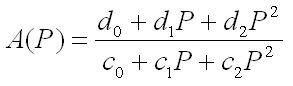
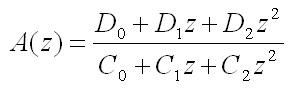
Substituting in this expression instead of the normalized complex variable

get the transfer function A (z) , which can be implemented in a digital filter:
The coefficients for the filter of the 2nd order will be determined by the following formulas:
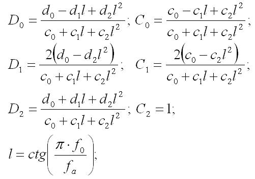
Where
 - clock frequency
 - filter cutoff frequency
d 0 ... 2 and c 0 ... 2 are the coefficients of the analog filter, it is assumed that you calculated them in advance.
Using these simple calculations and knowing the corresponding coefficients for the analog filter, we can calculate the coefficients for the digital transfer function of the filter of any order. (True, I only had enough up to the 4th order at one time, and there is no difficulty in it, I just have to write a lot of long formulas, simplifying using abbreviated multiplication formulas. But I remembered the distant school years). Before me, for example, was the task of implementing a filter with tunable characteristics, so all coefficients were calculated on a PC and transferred to the FPGA as 32-bit numbers converted to this in floating-point format.
So, having the coefficients of the digital transfer function, we substitute them into the difference equation of the IIR filter:

on the basis of which it is no longer difficult to write an implementation on Verilog.
The program is a complete module, ready for inclusion in an existing project. Input data is transmitted to it in the form of 18-bit integers. (It may be strange for someone to have such a bit depth, I will explain right away that the developed board uses an 18-bit AD764 ADC). Then they are converted to a 32-bit floating point format. This is done by means of the standard alter mega function int18_to_float32 . Addition and multiplication are implemented in the same way by standard functions sum_float32 and mul_float32, respectively. After performing the necessary calculations, the result is converted into an integer 18-bit number by the float32_to_int18 function. With the help of pre-calculated coefficients, this module can be turned into a low-pass, high-pass or band-pass filter.
Quartus II Project Archive 9.1
In addition to the books and data from Wikipedia already mentioned in the text, the reference manual Semiconductor Circuitry was used when writing the topic . Titze U., Schenk K. and Digital Filter Structures and Their Characteristics
I apologize for some confusion, because literary talent has never been my hallmark, and thank you for your attention.
Despite the fact that those who deal with this topic know everything from the below described, I want to give a start, to give quite a bit of theory for a wide circle of readers.
IIR filter (IIR filter) - filter with infinite impulse response (infinite impulse response). A distinctive feature of this type of filter from the FIR filter (filter with finite impulse response) is the presence of feedback when the value at the output of the filter depends not only on the input data, but also on the output data obtained by the filter on previous iterations. The structure of the IIR filter can be represented as follows:
I will not dwell on the methods of calculating the coefficients of the analog filter, this topic can be found in a large number of publications, such as Analog and Digital Filters. Calculation and implementation of G. Lem or Synthesis of filters. Herrero J. Willoner G. There are also many programs to do this. I will describe briefly only the process of converting an analog filter to digital.
Any filter can be represented using an analog transfer function. For example, for a second-order IIR filter, it will look like this:
Substituting in this expression instead of the normalized complex variable
get the transfer function A (z) , which can be implemented in a digital filter:
The coefficients for the filter of the 2nd order will be determined by the following formulas:
Where
- clock frequency - filter cutoff frequencyd 0 ... 2 and c 0 ... 2 are the coefficients of the analog filter, it is assumed that you calculated them in advance.
Using these simple calculations and knowing the corresponding coefficients for the analog filter, we can calculate the coefficients for the digital transfer function of the filter of any order. (True, I only had enough up to the 4th order at one time, and there is no difficulty in it, I just have to write a lot of long formulas, simplifying using abbreviated multiplication formulas. But I remembered the distant school years). Before me, for example, was the task of implementing a filter with tunable characteristics, so all coefficients were calculated on a PC and transferred to the FPGA as 32-bit numbers converted to this in floating-point format.
So, having the coefficients of the digital transfer function, we substitute them into the difference equation of the IIR filter:
on the basis of which it is no longer difficult to write an implementation on Verilog.
Module text
module LP_FILTER ( mhz_clk,RESET, D0,D1,D2,C0,C1, X,Y, COUNT ); // low pass filter INPUT32 OUTPUT32 /* y(i) = D2 * x(i) + D1 * x(i-1) + D0 * x(i-2) + C1 * y(i-1) + C0 * y(i-2) A(z) = (D0+D1*z+D2*z*z)/(C0+C1*z+z*z) <==> A(P) = (d0+d1*P+d2*P*P)/(c0+c1*P+c2*P*P) A(P) = 1/(1+1.4*P+P*P) LPF D0 = ( d0 - d1*l + d2*l*l)/(c0 + c1*l + c2*l*l) D1 = (2*d0 - 2*d2*l*l)/(c0 + c1*l + c2*l*l) D2 = ( d0 + d1*l + d2*l*l)/(c0 + c1*l + c2*l*l) C0 = -( c0 - c1*l + c2*l*l)/(c0 + c1*l + c2*l*l) C1 = -(2*c0 - 2*c2*l*l)/(c0 + c1*l + c2*l*l) l = ctg ( 3.14 * f_filt / f_samp ) */ input mhz_clk; input RESET; input [17:0] X; input [31:0] D0; input [31:0] D1; input [31:0] D2; input [31:0] C0; input [31:0] C1; output [17:0] Y; output [5:0] COUNT; // adc-filter counter reg [5:0] COUNT; always @( posedge mhz_clk,negedge RESET ) if (~RESET) COUNT[5:0] = 0; //49 count else if (COUNT[5:0] == 6'h31) COUNT[5:0] = 0; else COUNT[5:0] = COUNT[5:0] + 6'b1; // input - COUNT[4:0] = 24:49 // output - COUNT[4:0] = 6 reg [31:0] c0_y2; reg [31:0] c1_y1; reg [31:0] d0_x2; reg [31:0] d1_x1; reg [31:0] d2_x0; reg [31:0] y0; reg [31:0] y1; reg [31:0] y2; reg [31:0] x0; reg [31:0] x1; reg [31:0] x2; // y(i) = D2 * x(i) + D1 * x(i-1) + D0 * x(i-2) + C1 * y(i-1) + C0 * y(i-2) reg [31:0] mul_a; reg [31:0] mul_b; always @(*) if ( ( COUNT[5:0] >= 0 ) & ( COUNT[5:0] <= 4 ) | ( COUNT[5:0] == 49 ) ) mul_a[31:0] = x0[31:0]; else if ( ( COUNT[5:0] >= 5 ) & ( COUNT[5:0] <= 10 ) ) mul_a[31:0] = x1[31:0]; else if ( ( COUNT[5:0] >= 11 ) & ( COUNT[5:0] <= 16 ) ) mul_a[31:0] = x2[31:0]; else if ( ( COUNT[5:0] >= 17 ) & ( COUNT[5:0] <= 22 ) ) mul_a[31:0] = y1[31:0]; else mul_a[31:0] = y2[31:0]; always @(*) if ( ( COUNT[5:0] >= 0 ) & ( COUNT[5:0] <= 4 ) | ( COUNT[5:0] == 49 ) ) mul_b[31:0] = D2[31:0]; else if ( ( COUNT[5:0] >= 5 ) & ( COUNT[5:0] <= 10 ) ) mul_b[31:0] = D1[31:0]; else if ( ( COUNT[5:0] >= 11 ) & ( COUNT[5:0] <= 16 ) ) mul_b[31:0] = D0[31:0]; else if ( ( COUNT[5:0] >= 17 ) & ( COUNT[5:0] <= 22 ) ) mul_b[31:0] = C1[31:0]; else mul_b[31:0] = C0[31:0]; wire [31:0] mul_out; mul_float32 ( 1, mhz_clk, mul_a[31:0], mul_b[31:0], mul_out[31:0] ); reg [31:0] outmul; always @(*) outmul[31:0]=mul_out[31:0]; always @( posedge mhz_clk,negedge RESET ) if (~RESET) d2_x0[31:0] = 32'h0; else if ( COUNT[5:0] == 4 ) d2_x0[31:0] = mul_out[31:0]; always @( posedge mhz_clk,negedge RESET ) if (~RESET) d1_x1[31:0] = 32'h0; else if ( COUNT[5:0] == 10 ) d1_x1[31:0] = mul_out[31:0]; always @( posedge mhz_clk,negedge RESET ) if (~RESET) d0_x2[31:0] = 32'h0; else if ( COUNT[5:0] == 16 ) d0_x2[31:0] = mul_out[31:0]; always @( posedge mhz_clk,negedge RESET ) if (~RESET) c1_y1[31:0] = 32'h0; else if ( COUNT[5:0] == 22 ) c1_y1[31:0] = mul_out[31:0]; always @( posedge mhz_clk,negedge RESET ) if (~RESET) c0_y2[31:0] = 32'h0; else if ( COUNT[5:0] == 28 ) c0_y2[31:0] = mul_out[31:0]; // y(i) = D2 * x(i) + D1 * x(i-1) + D0 * x(i-2) + C1 * y(i-1) + C0 * y(i-2) reg [31:0] sum_a; reg [31:0] sum_b; always @(*) if ( ( COUNT[5:0] >= 0 ) & ( COUNT[5:0] <= 18 ) | ( COUNT[5:0] == 49 ) ) sum_a[31:0] = d2_x0[31:0]; else if ( ( COUNT[5:0] >= 19 ) & ( COUNT[5:0] <= 26 ) ) sum_a[31:0] = d0_x2[31:0]; else if ( ( COUNT[5:0] >= 27 ) & ( COUNT[5:0] <= 34 ) ) sum_a[31:0] = c1_y1[31:0]; else sum_a[31:0] = c0_y2[31:0]; always @(*) if ( ( COUNT[5:0] >= 0 ) & ( COUNT[5:0] <= 18 ) | ( COUNT[5:0] == 49 ) ) sum_b[31:0] = d1_x1[31:0]; else sum_b[31:0] = y0[31:0]; wire [31:0] sum_out; sum_float32 ( 1, mhz_clk, sum_a[31:0], sum_b[31:0], sum_out[31:0] ); reg [31:0] outsum; always @(*) outsum[31:0]=sum_out[31:0]; always @( posedge mhz_clk,negedge RESET ) if (~RESET) y0[31:0] = 32'h0; else if ( ( COUNT[5:0] == 18 ) | ( COUNT[5:0] == 26 ) | ( COUNT[5:0] == 34 ) | ( COUNT[5:0] == 42 ) ) y0[31:0] = sum_out[31:0]; reg [17:0] int_to_float_in; always @(*) begin int_to_float_in[17:0] = X[17:0];end wire [31:0] int_to_float_out; int18_to_float32 ( 1, mhz_clk, int_to_float_in[17:0], int_to_float_out[31:0] ); always @( posedge mhz_clk,negedge RESET ) if (~RESET) x0[31:0] = 32'h0; else if ( COUNT[5:0] == 49 ) x0[31:0] = int_to_float_out[31:0]; always @( posedge mhz_clk,negedge RESET ) if (~RESET) x1[31:0] = 32'h0; else if ( COUNT[5:0] == 49 ) x1[31:0] = x0[31:0]; always @( posedge mhz_clk,negedge RESET ) if (~RESET) x2[31:0] = 32'h0; else if ( COUNT[5:0] == 49 ) x2[31:0] = x1[31:0]; always @( posedge mhz_clk,negedge RESET ) if (~RESET) y1[31:0] = 32'h0; else if ( COUNT[5:0] == 49 ) y1[31:0] = sum_out[31:0]; always @( posedge mhz_clk,negedge RESET ) if (~RESET) y2[31:0] = 32'h0; else if ( COUNT[5:0] == 49 ) y2[31:0] = y1[31:0]; wire [17:0] float_to_int_out; wire nan; wire overflow; wire underflow; float32_to_int18 ( 1, mhz_clk, y0[31:0], nan, overflow, float_to_int_out[17:0], underflow ); reg [17:0] Y; always @( posedge mhz_clk ) if ( COUNT[4:0] == 6 ) Y[17:0] = float_to_int_out[17:0]; endmodule
module LP_FILTER ( mhz_clk,RESET, D0,D1,D2,C0,C1, X,Y, COUNT ); // low pass filter INPUT32 OUTPUT32 /* y(i) = D2 * x(i) + D1 * x(i-1) + D0 * x(i-2) + C1 * y(i-1) + C0 * y(i-2) A(z) = (D0+D1*z+D2*z*z)/(C0+C1*z+z*z) <==> A(P) = (d0+d1*P+d2*P*P)/(c0+c1*P+c2*P*P) A(P) = 1/(1+1.4*P+P*P) LPF D0 = ( d0 - d1*l + d2*l*l)/(c0 + c1*l + c2*l*l) D1 = (2*d0 - 2*d2*l*l)/(c0 + c1*l + c2*l*l) D2 = ( d0 + d1*l + d2*l*l)/(c0 + c1*l + c2*l*l) C0 = -( c0 - c1*l + c2*l*l)/(c0 + c1*l + c2*l*l) C1 = -(2*c0 - 2*c2*l*l)/(c0 + c1*l + c2*l*l) l = ctg ( 3.14 * f_filt / f_samp ) */ input mhz_clk; input RESET; input [17:0] X; input [31:0] D0; input [31:0] D1; input [31:0] D2; input [31:0] C0; input [31:0] C1; output [17:0] Y; output [5:0] COUNT; // adc-filter counter reg [5:0] COUNT; always @( posedge mhz_clk,negedge RESET ) if (~RESET) COUNT[5:0] = 0; //49 count else if (COUNT[5:0] == 6'h31) COUNT[5:0] = 0; else COUNT[5:0] = COUNT[5:0] + 6'b1; // input - COUNT[4:0] = 24:49 // output - COUNT[4:0] = 6 reg [31:0] c0_y2; reg [31:0] c1_y1; reg [31:0] d0_x2; reg [31:0] d1_x1; reg [31:0] d2_x0; reg [31:0] y0; reg [31:0] y1; reg [31:0] y2; reg [31:0] x0; reg [31:0] x1; reg [31:0] x2; // y(i) = D2 * x(i) + D1 * x(i-1) + D0 * x(i-2) + C1 * y(i-1) + C0 * y(i-2) reg [31:0] mul_a; reg [31:0] mul_b; always @(*) if ( ( COUNT[5:0] >= 0 ) & ( COUNT[5:0] <= 4 ) | ( COUNT[5:0] == 49 ) ) mul_a[31:0] = x0[31:0]; else if ( ( COUNT[5:0] >= 5 ) & ( COUNT[5:0] <= 10 ) ) mul_a[31:0] = x1[31:0]; else if ( ( COUNT[5:0] >= 11 ) & ( COUNT[5:0] <= 16 ) ) mul_a[31:0] = x2[31:0]; else if ( ( COUNT[5:0] >= 17 ) & ( COUNT[5:0] <= 22 ) ) mul_a[31:0] = y1[31:0]; else mul_a[31:0] = y2[31:0]; always @(*) if ( ( COUNT[5:0] >= 0 ) & ( COUNT[5:0] <= 4 ) | ( COUNT[5:0] == 49 ) ) mul_b[31:0] = D2[31:0]; else if ( ( COUNT[5:0] >= 5 ) & ( COUNT[5:0] <= 10 ) ) mul_b[31:0] = D1[31:0]; else if ( ( COUNT[5:0] >= 11 ) & ( COUNT[5:0] <= 16 ) ) mul_b[31:0] = D0[31:0]; else if ( ( COUNT[5:0] >= 17 ) & ( COUNT[5:0] <= 22 ) ) mul_b[31:0] = C1[31:0]; else mul_b[31:0] = C0[31:0]; wire [31:0] mul_out; mul_float32 ( 1, mhz_clk, mul_a[31:0], mul_b[31:0], mul_out[31:0] ); reg [31:0] outmul; always @(*) outmul[31:0]=mul_out[31:0]; always @( posedge mhz_clk,negedge RESET ) if (~RESET) d2_x0[31:0] = 32'h0; else if ( COUNT[5:0] == 4 ) d2_x0[31:0] = mul_out[31:0]; always @( posedge mhz_clk,negedge RESET ) if (~RESET) d1_x1[31:0] = 32'h0; else if ( COUNT[5:0] == 10 ) d1_x1[31:0] = mul_out[31:0]; always @( posedge mhz_clk,negedge RESET ) if (~RESET) d0_x2[31:0] = 32'h0; else if ( COUNT[5:0] == 16 ) d0_x2[31:0] = mul_out[31:0]; always @( posedge mhz_clk,negedge RESET ) if (~RESET) c1_y1[31:0] = 32'h0; else if ( COUNT[5:0] == 22 ) c1_y1[31:0] = mul_out[31:0]; always @( posedge mhz_clk,negedge RESET ) if (~RESET) c0_y2[31:0] = 32'h0; else if ( COUNT[5:0] == 28 ) c0_y2[31:0] = mul_out[31:0]; // y(i) = D2 * x(i) + D1 * x(i-1) + D0 * x(i-2) + C1 * y(i-1) + C0 * y(i-2) reg [31:0] sum_a; reg [31:0] sum_b; always @(*) if ( ( COUNT[5:0] >= 0 ) & ( COUNT[5:0] <= 18 ) | ( COUNT[5:0] == 49 ) ) sum_a[31:0] = d2_x0[31:0]; else if ( ( COUNT[5:0] >= 19 ) & ( COUNT[5:0] <= 26 ) ) sum_a[31:0] = d0_x2[31:0]; else if ( ( COUNT[5:0] >= 27 ) & ( COUNT[5:0] <= 34 ) ) sum_a[31:0] = c1_y1[31:0]; else sum_a[31:0] = c0_y2[31:0]; always @(*) if ( ( COUNT[5:0] >= 0 ) & ( COUNT[5:0] <= 18 ) | ( COUNT[5:0] == 49 ) ) sum_b[31:0] = d1_x1[31:0]; else sum_b[31:0] = y0[31:0]; wire [31:0] sum_out; sum_float32 ( 1, mhz_clk, sum_a[31:0], sum_b[31:0], sum_out[31:0] ); reg [31:0] outsum; always @(*) outsum[31:0]=sum_out[31:0]; always @( posedge mhz_clk,negedge RESET ) if (~RESET) y0[31:0] = 32'h0; else if ( ( COUNT[5:0] == 18 ) | ( COUNT[5:0] == 26 ) | ( COUNT[5:0] == 34 ) | ( COUNT[5:0] == 42 ) ) y0[31:0] = sum_out[31:0]; reg [17:0] int_to_float_in; always @(*) begin int_to_float_in[17:0] = X[17:0];end wire [31:0] int_to_float_out; int18_to_float32 ( 1, mhz_clk, int_to_float_in[17:0], int_to_float_out[31:0] ); always @( posedge mhz_clk,negedge RESET ) if (~RESET) x0[31:0] = 32'h0; else if ( COUNT[5:0] == 49 ) x0[31:0] = int_to_float_out[31:0]; always @( posedge mhz_clk,negedge RESET ) if (~RESET) x1[31:0] = 32'h0; else if ( COUNT[5:0] == 49 ) x1[31:0] = x0[31:0]; always @( posedge mhz_clk,negedge RESET ) if (~RESET) x2[31:0] = 32'h0; else if ( COUNT[5:0] == 49 ) x2[31:0] = x1[31:0]; always @( posedge mhz_clk,negedge RESET ) if (~RESET) y1[31:0] = 32'h0; else if ( COUNT[5:0] == 49 ) y1[31:0] = sum_out[31:0]; always @( posedge mhz_clk,negedge RESET ) if (~RESET) y2[31:0] = 32'h0; else if ( COUNT[5:0] == 49 ) y2[31:0] = y1[31:0]; wire [17:0] float_to_int_out; wire nan; wire overflow; wire underflow; float32_to_int18 ( 1, mhz_clk, y0[31:0], nan, overflow, float_to_int_out[17:0], underflow ); reg [17:0] Y; always @( posedge mhz_clk ) if ( COUNT[4:0] == 6 ) Y[17:0] = float_to_int_out[17:0]; endmodule
The program is a complete module, ready for inclusion in an existing project. Input data is transmitted to it in the form of 18-bit integers. (It may be strange for someone to have such a bit depth, I will explain right away that the developed board uses an 18-bit AD764 ADC). Then they are converted to a 32-bit floating point format. This is done by means of the standard alter mega function int18_to_float32 . Addition and multiplication are implemented in the same way by standard functions sum_float32 and mul_float32, respectively. After performing the necessary calculations, the result is converted into an integer 18-bit number by the float32_to_int18 function. With the help of pre-calculated coefficients, this module can be turned into a low-pass, high-pass or band-pass filter.
Quartus II Project Archive 9.1
In addition to the books and data from Wikipedia already mentioned in the text, the reference manual Semiconductor Circuitry was used when writing the topic . Titze U., Schenk K. and Digital Filter Structures and Their Characteristics
I apologize for some confusion, because literary talent has never been my hallmark, and thank you for your attention.
')
Source: https://habr.com/ru/post/145703/
All Articles