Programmable light switch with remote control
Continuation of previously published articles, first , second .
This article will focus on a programmable light switch with a remote control. Like past projects for debugging and prototyping, I use Carduino Nano V.7
Required functionality
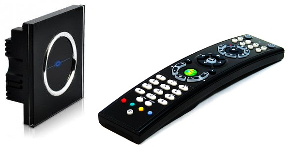
The ability to control the switch with any household IR remote control.
Program the switch to any button of the household IR remote control.
Turn on / off the light, both from the switch key and from the remote, regardless of each other.
Scheme and accessories
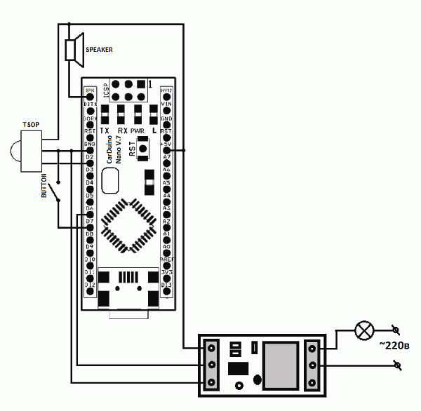
To build the prototype used the following components:
Carduino Nano V.7 Controller
Relay Module
IR receiver TSOP
Bread board
Sound Emitter
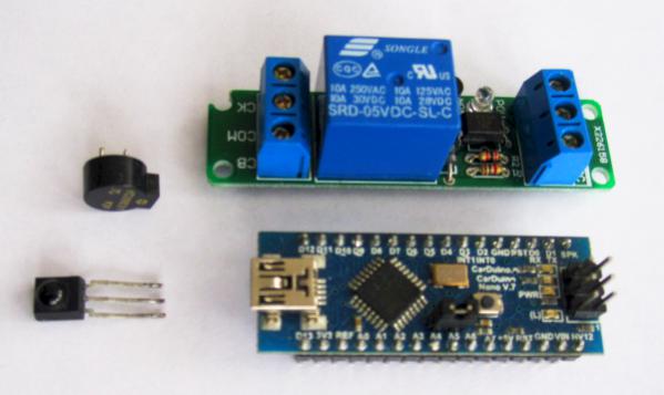
')
Photograph of components
Switch operation description
At first we add the code of the button of the control panel to the memory of the switch. To do this, we take the most suitable remote control for us (the remote control from the air conditioner will not work) and select a free button on it that you never use (usually the colored teletext buttons). We enter the switch programming mode, for this you need to press the on / off key and hold for 5 seconds, a long beep will sound, then it remains to press the previously selected remote control button and your switch is ready for operation. Now the light switch will understand the command of your IR remote control added to it. The button code is stored in the non-volatile memory of the controller and will be stored in memory even after the power supply to the circuit is turned off.
The operation of the prototype switch, see the video
Code for Arduino controller
#include <IRremote.h> #include <avr/delay.h> #include <EEPROM.h> #define button 7 #define speaker 11 #define lamp 6 IRrecv irrecv(2); // decode_results results; unsigned long ir_command; uint8_t swt, count, state = 0; // void setup() { pinMode(speaker, OUTPUT);// pinMode(button, INPUT);// digitalWrite(button,HIGH);// pinMode(lamp, OUTPUT);// irrecv.enableIRIn(); // } void loop() { swt=digitalRead(button); count=0; while(swt==0) { if(count>30) { beep(100,400); for(unsigned long i=0; i<2000000; i++) { if (irrecv.decode(&results)) { SaveEEPROM(results.value); irrecv.resume(); break; } } beep(30,900); break; } count++; swt=digitalRead(button); _delay_ms(100); } ir_command=LoadEEPROM(); if (irrecv.decode(&results)) { if(ir_command==results.value) { state=~state; digitalWrite(lamp, state); beep(10,300); _delay_ms(700); } irrecv.resume(); } else if(count>1) { state=~state; digitalWrite(lamp, state); beep(10,500); _delay_ms(100); } } void SaveEEPROM(unsigned long ir_code) { EEPROM.write(0, ir_code & 0xFF); EEPROM.write(1, (ir_code & 0xFF00) >> 8); EEPROM.write(2, (ir_code & 0xFF0000) >> 16); EEPROM.write(3, (ir_code & 0xFF000000) >> 24); } unsigned long LoadEEPROM() { byte val = EEPROM.read(3); unsigned long ir_code=val; val = EEPROM.read(2); ir_code= (ir_code << 8) | val; val = EEPROM.read(1); ir_code= (ir_code << 8) | val; val = EEPROM.read(0); ir_code= (ir_code << 8) | val; return ir_code; } void beep(byte dur, word frq) { dur=(1000/frq)*dur; for(byte i=0; i<dur; i++) { digitalWrite(speaker, HIGH); _delay_us(frq); digitalWrite(speaker, LOW); _delay_us(frq); } } To compile the code you need to add the library IRemote . The library is different from the original, as I added several protocols to it, including the new protocol of Samsung LED TVs
Circuit Breaker
After debugging the device on the arduino, I drew the final circuit of the future switch. Since I already wrote earlier that Arduino is a convenient tool for debugging and writing code, but it will not work for the final circuit.
Hex file for Atmega168 controller firmware
The power supply can be used from a mobile phone charger.
Power supply circuits.
If you have questions, ask, I will answer them with pleasure.
Source: https://habr.com/ru/post/145653/
All Articles