Cisco UCS Blade: a new approach to building a data center
Almost every year in the IT world comes a new trend. For example, in 2007 it was data consolidation on the storage system, in 2008-2009 - the blade systems, 2010 was a year of virtualization, and since 2011, the idea of consolidating data networks has been actively developing. UCS includes all of the above features, and also has improved fault tolerance and scalability.
First, let's look at the Cisco blade system architecture:

')
Highlight the main components:
1) Fabric Interconnect - Nexus 5000 based switches with built-in UCS Manager functionality that allows you to manage all servers, BIOS settings, component firmware, switches, routing, virtualization, and automation. They also allow working with Ethernet and SAN networks and fully support the FCoE protocol.
2) UCS 5108 Blade Chassis - the chassis into which the blade servers (blade servers) are installed. It is used as a centralized cooling system for servers and power supply to servers.
3) Fabric Extender (FEX) - extends Fabric Interconnect to the blade chassis by paging multiple 10 Gbps connections between the blade servers and Fabric Interconnect. Not a switch. Managed as an extender to the Fabric Interconnect switch. Manages power supplies and fans. Mounted on the back of the blade chassis.
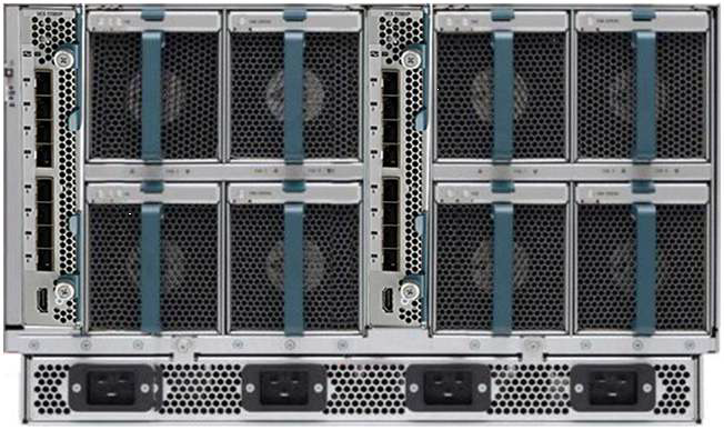
Based on the architecture, we can connect up to 40 blade chassis to one pair of Fabric Interconnect switches, managing all of them from a single point (UCS Manager). We also do not need to buy separate switches for each blade chassis, which allows us to save when expanding the fleet of blade servers.
4) Virtual Interface Card (VIC) - specialized network adapters from Cisco. Allow to pass several network links through a single communication channel. In this case, the processing of all network traffic is done by the adapter itself. A detailed diagram is shown in the figure:
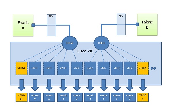
Each adapter, be it 10, 20 or 40 Gbps, can be divided into 128 virtual ones. The technology is based on the IEEE 802.1bn standard. Creating a new network adapter, you can specify it:
- speed, with a stroke of 1Mbps.
- QoS priority.
- type: Ethernet or FCoE.
- The mechanism of the Failover.
- VLAN / VSAN.
What do we have in the end? Easy administration of each adapter, reducing the number of cables for the connection between the server and the switch, and a flexible system for adding new devices to the server.
This system is ideal for virtualization tasks. After all, with a large number of network adapters in the server, we do not need to use a virtual switch hypervisor. It is enough to make a direct forwarding of each of the adapters to the virtual machines.
To understand the principles of Cisco UCS failover, let's look at the basic structure of server traffic transmission. The UCS consists of a blade chassis and fabric interconnect (FI). The blade chassis holds the blade servers, and FI performs LAN switching, SAN, and controls the chassis / servers.
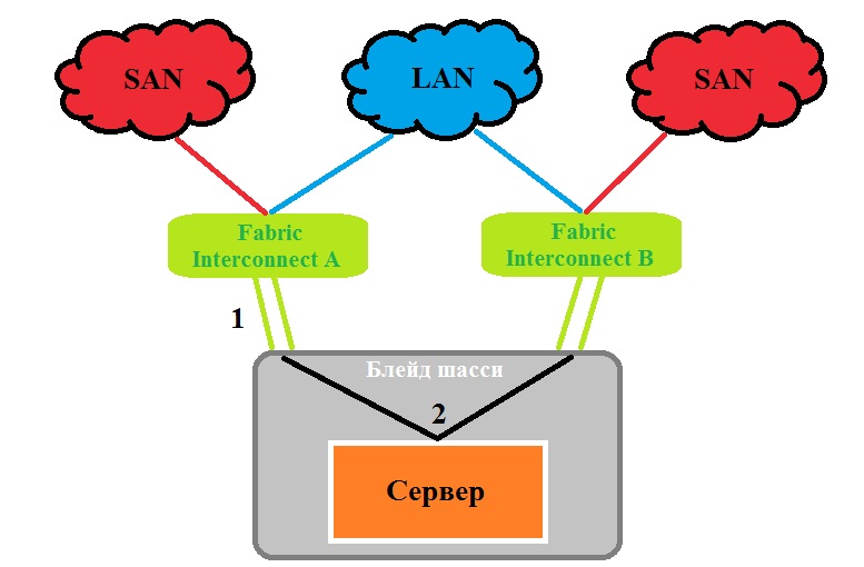
The number 1 denotes connections between FEX and FI, which can be from one to eight. Each connection has a speed of 10 Gbit / s. Thus, eight servers located within each chassis can be routed from 20 to 160 Gbps from central Fabric Interconnect switches.
Connections can be configured to work in EtherChannel mode or to allocate a separate interface for each server. Depending on the type of task, network adapters with speeds of 20, 40 or 80 Gb / s can be installed in the server. In any case, if one of the links fails, its traffic will be distributed between adjacent links. The speed of each virtual adapter can be limited by the Quality of Service (QoS) and Enhanced Transmission Selection (ETS) mechanisms.
UCS has a unique feature, available on some VIC adapters, that allows you to identify a broken network section and perform a “failover” to the neighboring Fabric Interconnect. Some mezzanine cards (VIC) have a built-in mini-switch that allows you to switch gears from path A to path B and back. This is schematically shown in the figure:
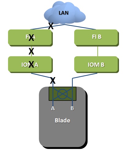
Hardware UCS failover provides better fault tolerance than traditional NIC-teaming, thanks to the intelligent switching system built into FI. In the picture above, the HW Failover determines: a breakdown in the chassis, in the FEX, or in the interface of the network adapter. In addition, if FI loses an external connection to a LAN network, it will send a message to the VIC adapter and allow switching to the backup path. In the picture, any failure in places marked X will cause Ethernet traffic to be switched to path B. Hardware UCS failover applies only to Ethernet networks, since SAN networks have their own failover mechanism, thanks to the multipath mechanism.
MUK-Service - all types of IT repair: warranty, non-warranty repair, sale of spare parts, contract service
Scalability
First, let's look at the Cisco blade system architecture:
')
Highlight the main components:
1) Fabric Interconnect - Nexus 5000 based switches with built-in UCS Manager functionality that allows you to manage all servers, BIOS settings, component firmware, switches, routing, virtualization, and automation. They also allow working with Ethernet and SAN networks and fully support the FCoE protocol.
2) UCS 5108 Blade Chassis - the chassis into which the blade servers (blade servers) are installed. It is used as a centralized cooling system for servers and power supply to servers.
3) Fabric Extender (FEX) - extends Fabric Interconnect to the blade chassis by paging multiple 10 Gbps connections between the blade servers and Fabric Interconnect. Not a switch. Managed as an extender to the Fabric Interconnect switch. Manages power supplies and fans. Mounted on the back of the blade chassis.
Based on the architecture, we can connect up to 40 blade chassis to one pair of Fabric Interconnect switches, managing all of them from a single point (UCS Manager). We also do not need to buy separate switches for each blade chassis, which allows us to save when expanding the fleet of blade servers.
4) Virtual Interface Card (VIC) - specialized network adapters from Cisco. Allow to pass several network links through a single communication channel. In this case, the processing of all network traffic is done by the adapter itself. A detailed diagram is shown in the figure:
Each adapter, be it 10, 20 or 40 Gbps, can be divided into 128 virtual ones. The technology is based on the IEEE 802.1bn standard. Creating a new network adapter, you can specify it:
- speed, with a stroke of 1Mbps.
- QoS priority.
- type: Ethernet or FCoE.
- The mechanism of the Failover.
- VLAN / VSAN.
What do we have in the end? Easy administration of each adapter, reducing the number of cables for the connection between the server and the switch, and a flexible system for adding new devices to the server.
This system is ideal for virtualization tasks. After all, with a large number of network adapters in the server, we do not need to use a virtual switch hypervisor. It is enough to make a direct forwarding of each of the adapters to the virtual machines.
fault tolerance
To understand the principles of Cisco UCS failover, let's look at the basic structure of server traffic transmission. The UCS consists of a blade chassis and fabric interconnect (FI). The blade chassis holds the blade servers, and FI performs LAN switching, SAN, and controls the chassis / servers.
The number 1 denotes connections between FEX and FI, which can be from one to eight. Each connection has a speed of 10 Gbit / s. Thus, eight servers located within each chassis can be routed from 20 to 160 Gbps from central Fabric Interconnect switches.
Connections can be configured to work in EtherChannel mode or to allocate a separate interface for each server. Depending on the type of task, network adapters with speeds of 20, 40 or 80 Gb / s can be installed in the server. In any case, if one of the links fails, its traffic will be distributed between adjacent links. The speed of each virtual adapter can be limited by the Quality of Service (QoS) and Enhanced Transmission Selection (ETS) mechanisms.
UCS has a unique feature, available on some VIC adapters, that allows you to identify a broken network section and perform a “failover” to the neighboring Fabric Interconnect. Some mezzanine cards (VIC) have a built-in mini-switch that allows you to switch gears from path A to path B and back. This is schematically shown in the figure:
Hardware UCS failover provides better fault tolerance than traditional NIC-teaming, thanks to the intelligent switching system built into FI. In the picture above, the HW Failover determines: a breakdown in the chassis, in the FEX, or in the interface of the network adapter. In addition, if FI loses an external connection to a LAN network, it will send a message to the VIC adapter and allow switching to the backup path. In the picture, any failure in places marked X will cause Ethernet traffic to be switched to path B. Hardware UCS failover applies only to Ethernet networks, since SAN networks have their own failover mechanism, thanks to the multipath mechanism.
MUK-Service - all types of IT repair: warranty, non-warranty repair, sale of spare parts, contract service
Source: https://habr.com/ru/post/145473/
All Articles