Aircraft control systems architecture
"We work so that you are not afraid to fly"

Figure 1. Model Bombardier BD 500 in a wind tunnel
This is the slogan I somehow came up with for my work. It is the best way to express the essence of the development of aircraft control systems. And, honestly, I would like this to be the motto of all developers of modern aircraft control systems around the world. Because, despite the fact that you can often hear that the plane is one of the safest modes of transport, thousands of people around the world are afraid to fly, cling to the arms of their seats ... And often the cause of all fears is uncertainty. When you need to trust such a fragile design, dangling kilometers above the ground, such a fragile interlacing of wires and bits of code, a hidden curtain of smiles of flight attendants and secrets of program code. And which should be opened.
')
To my surprise, my previous article caused an unexpectedly large response both on Habré and beyond. I was asked a series of questions and expressed a number of discontent, rightfully calling it a “closed area”. Contrary to this opinion, everything that I talked about in the article and what it will be about in this one can be found on the Internet. It may be in separate pieces, perhaps in different languages, but no fact is know-how. The task of my article is to acquaint the reader with the wonderful field of aviation and classify all the experience and knowledge that I was able to accumulate. As for the problematic issues and questions raised by me, I would like to recall a similar case described by Mr. Feynman in the wonderful book “What do you care about what others think of you?”. If someone has not read, be sure to read. There Richard talks about the problems at NASA. About the problems that led to the crash of the shuttle. And that the equipment, programs, programmers who wrote them are not always to blame, and often tolerances, concealment of facts and conservative decisions made are often to blame. And you know what? NASA because of this case and publicity did not become worse, but only learned from its sad though, but experience. Prestige not only did not fall, but grew, NASA proved to be an organization that knows how to solve problems and recognize them. Because, like space, as well as aviation, are splendid areas in which great companies and dedicated people work. And do not believe those who say that after installing toilets in airplanes, the sky has ceased to be a place for romantics.
Automation is great. It's essential. It reduces fatigue, and enhances safety. But what if it breaks?
All of you, of course, know that Murphy's laws work, and one of them says that anything that can break will break. Anything that can not break - also breaks. Whatever the percentage of equipment failure, the probability of failure exists. But there are methods to minimize these failures. And, first of all, these are the architectural features of the software and hardware complex.

Figure 2. T-4
Modern aircraft is controlled by the so-called EDSU - Electro Distance Control System. In fact, this is not so new. For the first time such a system was installed on the Soviet Maxim Gorky aircraft, controlling the surfaces by transmitting electric current (analogue EDSU). Later, in military technology, it will appear in a fully digital form on the Soviet T-4 , and in civil aviation on the Airbus A320 and Tu-204 . However, nothing stands still and technologies are being improved, new approaches are being developed and new levels of security are being achieved.
What is EDSU? First of all, it is a software and hardware complex consisting of:
Each system is usually at least duplicated once. Depending on the required control laws, pricing and layout decisions, the architecture may vary - contain more contours of duplication, control, power circuits, or, conversely, less. As well as possible combinations of EDSU and mechanical, hydromechanical control systems.
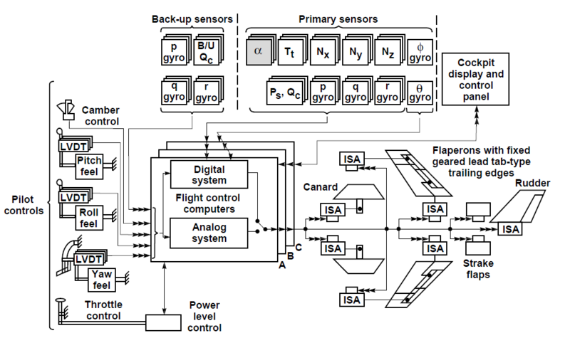
Fig 3. block diagram of the EDSU
The use of EDSU in the first place provides a significant reduction in the weight of the control system, which is of critical importance on large aircraft. It also gives more flexible layout options, often allows you to locate the control system in almost any available location of the aircraft. By the way, therefore, wire -by-wire ( fly-by-wire ) is still the most popular, because it is not as complicated and capricious as fly-by-light (using optics) or fly-by-wireless (with using wireless technologies). Reducing the weight and simplifying the layout allows you to enter additional circuits to ensure the normal control of the aircraft in a state of failure of one of the previously worked circuits. It allows you to reduce the human factor whenever possible by controlling the flight parameters in automatic mode and correcting the commands of the pilots. Monitors the status of critical aircraft systems in real time, which allows to detect, track and, if possible, correct the error in the shortest possible time.
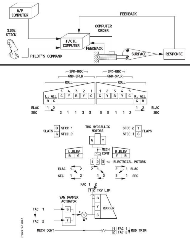
Fig 4. functional diagram of the EMF
However, in the process of designing such systems, it is crucial to create the right architecture. This is the most vulnerable spot of the EDSU. The most classic cases of errors are:
Whatever the architecture of control systems, they are united by the following things:
Unfortunately, I have no idea about the technologies that were used in Soviet aircraft, but I think it is similar to the modern approach, which is valid for both foreign and Russian projects.
A typical control system consists of:

Figure 5. EDS Boeing 777
Depending on the complexity of the system, additional devices may be added \ existing ones. In any case, with proper duplication and design of the system, the main principle is the observance of the principle of “dissimilarity”, which means that for each element working in the duplication mode different electronic components, processors, programming languages should be applied, different code written and the connecting wires are laid independently in different ways.
Management computers (PFCs) and executive units (ACEs) consist of several independent channels. In the simplest case, they consist of a control channel that calculates a command for execution (Control Channel) and a control channel that checks the correctness of commands (Monitor Channel). For simplicity, we can say that the first should produce the most accurate data calculated using complex control laws based on dynamic models of aircraft behavior, and the second should give a correct assessment based on an assessment of the environment coming from the sensors with accepting and assuming some “average variant ”, But doing it faster than the control channel, having the ability to block a new incorrect signal before the command is executed and the error is processed.
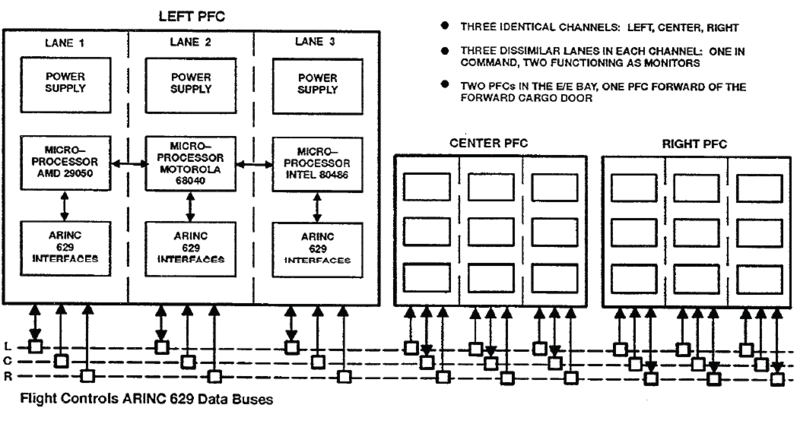
Figure 6. PFC architecture diagram for Boeing 777
Depending on the project, a different number of modules and different combinations of channels within them are used. In Boeing-777, for example, three main computers with three channels each. And each channel can play different roles, but invariably one of them is the control channel, and the other two are controls. In Boeing, for example, a circuit with 1 MC, 1 CC and 1 hot-swap channel (standby) is popular. In other layouts, a channel can also be made separately for controlling power electronics, or for commissioning and design purposes, such as an Extender Board or Fault Insertion Board. The communication between the channels usually takes place over the CAN bus or any other reasonably fast bus such as spacewire , 1394 , etc. ... The main criterion is the data transfer rate.
Communication between control and periphery modules in aviation is traditionally carried out via the ARINC bus. In general, the main criterion is reliability even at large distances.
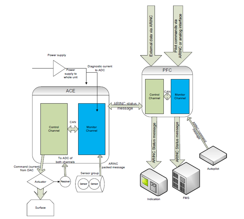
Figure 7. Simplified diagram of a typical implementation of the control system
Also used directly analog and digital signals. The classic layout is the use of ADC \ DAC (analog-digital and digital-analog converters) inside the ACE for interrogating sensors and for commanding drives, as well as using Resolvers for their sensitive control. Use of discrete signals - for synchronization (including from the clock generators), pin-coding (determining the position and role of the module) modules. Modules are usually aware of each other’s state and in many cases the architecture implies a “hot” start when the backup module picks up the main state and goes into active mode, replacing the previous main module within a couple of seconds. ACE and PFC are LRU (Line Replaceable Unit) modules, i.e., linear replacement modules, which implies the possibility of replacing one module (as an expansion card) with a similar one without the need to replace (modify) the entire communication system. A similar architecture is used for components of the system separately, for such a system for controlling the chassis, hydraulics, and hatches.
Making decisions based on the collaboration of various devices is a complex question that cannot be answered unambiguously. There are different solutions: synchronization, solution using the average method using state (error) data, ways to detect faulty modules and disable them, scripts. For example, when using three PFCs in the presence of two identical commands and one excellent one, the excellent one will be rejected. With three different - the system will be disabled, as with different readings in a system using only two PFCs. There can be a lot of different logics, as well as including work algorithms for duplicating the EDSU with a mechanical control system. In the latter case, the probability of failure increases, because when the mechanical control system fails, the EDSU should be informed of the failure and react to this by switching to emergency mode.
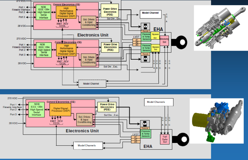
Fig. 8. Pairing design of ACE for electro-hydraulic system
Depending on the environment, the system can operate in different modes . Typical modes are:
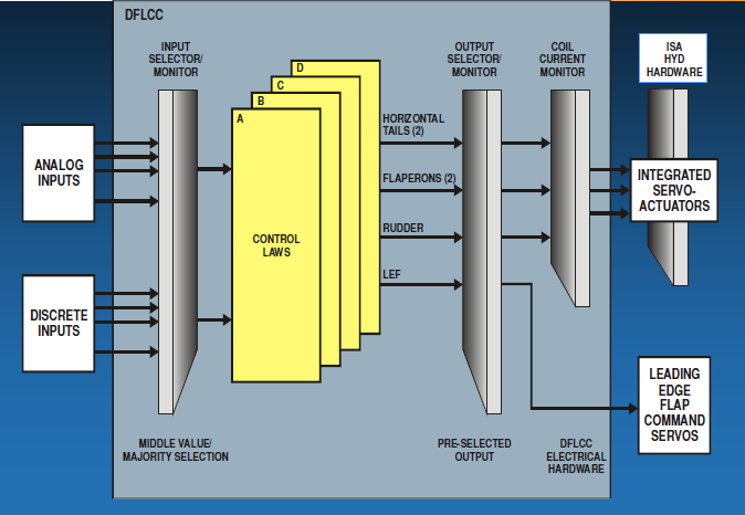
Figure 9. The scheme of work with four PFC.
In order not to go into technical details and specific implementations, I will briefly summarize: each system is duplicated. So, in addition to the control modules, power supply circuits (three and more), magnetic locks, sensors, messages from devices, control knobs are duplicated. Each information requires confirmation. So, to diagnose an error depending on its criticality, it takes time to confirm it (so as not to shut down the system ahead of time due to interference), usually from different devices at once. Even in the event of a failure or even multiple failures, it is possible to operate in an alternative mode. This is achieved through the use of various hardware and software. So, for the same device, different processors and a circuit board for different channels are used. For example, for the Control Channel - a processor from Motorola, and for the Monitor - from Infineon, for another LRU - from Texas Instruments, etc ... Different compilers are used, different code is written. Ideally, for different PFC \ ACE there should also be different software and hardware solutions, but in the simple case (it is not always possible and feasible both technically and financially) dissimilarity is achieved by different pin-coding and different arrangement of modules in space. The system is ideally protected from fools. In the first place - from the human factor. Subsequent - from critical conditions (short circuit modes, power loss, high and low temperatures), as well as from an impossible event according to Murphy. In the code, this translates, for example, into paronoidal programming .
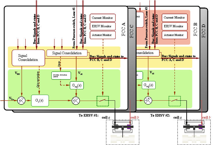
Figure 10. Four PFCs are paired up.
Familiar with the typical Coding Standard will recognize the implementation of the usual rules in this code. In general, this code is not the best and most optimal, however, it guarantees the exclusion of impossible situations:
On this, perhaps, it is necessary to complete the article and this topic in particular. In conclusion, I want to say that whatever the system, solutions are complex like Boeing or simple, like in the beginning Chinese aviation industry, the systems are developing in the direction of convenience and safety. And every protected wire and bit is the work of many people, often enthusiasts, working in this field, as well as you, citizens and passengers, who with their love for him and his criticism of human imperfection makes this life better.
PS By the way, at the time of this writing, it turned out that the Boeing 777 management software was written on ada.
Figure 1. Model Bombardier BD 500 in a wind tunnel
This is the slogan I somehow came up with for my work. It is the best way to express the essence of the development of aircraft control systems. And, honestly, I would like this to be the motto of all developers of modern aircraft control systems around the world. Because, despite the fact that you can often hear that the plane is one of the safest modes of transport, thousands of people around the world are afraid to fly, cling to the arms of their seats ... And often the cause of all fears is uncertainty. When you need to trust such a fragile design, dangling kilometers above the ground, such a fragile interlacing of wires and bits of code, a hidden curtain of smiles of flight attendants and secrets of program code. And which should be opened.
')
To my surprise, my previous article caused an unexpectedly large response both on Habré and beyond. I was asked a series of questions and expressed a number of discontent, rightfully calling it a “closed area”. Contrary to this opinion, everything that I talked about in the article and what it will be about in this one can be found on the Internet. It may be in separate pieces, perhaps in different languages, but no fact is know-how. The task of my article is to acquaint the reader with the wonderful field of aviation and classify all the experience and knowledge that I was able to accumulate. As for the problematic issues and questions raised by me, I would like to recall a similar case described by Mr. Feynman in the wonderful book “What do you care about what others think of you?”. If someone has not read, be sure to read. There Richard talks about the problems at NASA. About the problems that led to the crash of the shuttle. And that the equipment, programs, programmers who wrote them are not always to blame, and often tolerances, concealment of facts and conservative decisions made are often to blame. And you know what? NASA because of this case and publicity did not become worse, but only learned from its sad though, but experience. Prestige not only did not fall, but grew, NASA proved to be an organization that knows how to solve problems and recognize them. Because, like space, as well as aviation, are splendid areas in which great companies and dedicated people work. And do not believe those who say that after installing toilets in airplanes, the sky has ceased to be a place for romantics.
Automation is great. It's essential. It reduces fatigue, and enhances safety. But what if it breaks?
All of you, of course, know that Murphy's laws work, and one of them says that anything that can break will break. Anything that can not break - also breaks. Whatever the percentage of equipment failure, the probability of failure exists. But there are methods to minimize these failures. And, first of all, these are the architectural features of the software and hardware complex.
Figure 2. T-4
Modern aircraft is controlled by the so-called EDSU - Electro Distance Control System. In fact, this is not so new. For the first time such a system was installed on the Soviet Maxim Gorky aircraft, controlling the surfaces by transmitting electric current (analogue EDSU). Later, in military technology, it will appear in a fully digital form on the Soviet T-4 , and in civil aviation on the Airbus A320 and Tu-204 . However, nothing stands still and technologies are being improved, new approaches are being developed and new levels of security are being achieved.
EDSU
What is EDSU? First of all, it is a software and hardware complex consisting of:
- Drives control surfaces of the aircraft
- Control sensors
- Control systems
- Display systems and auxiliary systems
- Communication and power systems
Each system is usually at least duplicated once. Depending on the required control laws, pricing and layout decisions, the architecture may vary - contain more contours of duplication, control, power circuits, or, conversely, less. As well as possible combinations of EDSU and mechanical, hydromechanical control systems.
Fig 3. block diagram of the EDSU
The use of EDSU in the first place provides a significant reduction in the weight of the control system, which is of critical importance on large aircraft. It also gives more flexible layout options, often allows you to locate the control system in almost any available location of the aircraft. By the way, therefore, wire -by-wire ( fly-by-wire ) is still the most popular, because it is not as complicated and capricious as fly-by-light (using optics) or fly-by-wireless (with using wireless technologies). Reducing the weight and simplifying the layout allows you to enter additional circuits to ensure the normal control of the aircraft in a state of failure of one of the previously worked circuits. It allows you to reduce the human factor whenever possible by controlling the flight parameters in automatic mode and correcting the commands of the pilots. Monitors the status of critical aircraft systems in real time, which allows to detect, track and, if possible, correct the error in the shortest possible time.
Fig 4. functional diagram of the EMF
However, in the process of designing such systems, it is crucial to create the right architecture. This is the most vulnerable spot of the EDSU. The most classic cases of errors are:
- the dependence of the system on the power supply, which in the case of mechanical control is a disaster, but does not lead to the loss of control of the entire aircraft ( landing Tu-154 ).
- incorrect duplication of the management system ( incident with the An-148 )
- "Stupid" software errors, such as a change of sign when crossing the equator or time zones , the possibility of a negative speed on a civilian plane, etc.
Whatever the architecture of control systems, they are united by the following things:
- management duplication
- the presence of a response signal ( feedback )
- self-control system (division into the control and monitoring part).
Unfortunately, I have no idea about the technologies that were used in Soviet aircraft, but I think it is similar to the modern approach, which is valid for both foreign and Russian projects.
Control system
A typical control system consists of:
- PFC - Primary Flight Computer - central control computer, which includes all control laws and which is able to analyze all incoming data from sensors and feedback and give the data to the execution of electronics. PFC in airplanes is like 1 (in the most either simple or cheap systems), both 2 and 3. PFC work in a regular mode together and simultaneously.
- ACE - Actuator Control Electronic - executive control modules by actuators (drives). They include part of the surface control logic in case of failure of the main computer. Transmit directly to the execution command of the actuators. Depending on the types, they are designed to control both electric and hydraulic drives. Any ACE is also duplicated depending on the architecture. AACE with alternate substitute works alternately.
- Control knobs (steering wheel / knob (sidestick), pedals, etc.).
- Indicators \ information screens.
- Actuators.
- Power electronics (if not included in the control modules).
Figure 5. EDS Boeing 777
Depending on the complexity of the system, additional devices may be added \ existing ones. In any case, with proper duplication and design of the system, the main principle is the observance of the principle of “dissimilarity”, which means that for each element working in the duplication mode different electronic components, processors, programming languages should be applied, different code written and the connecting wires are laid independently in different ways.
Control electronics
Management computers (PFCs) and executive units (ACEs) consist of several independent channels. In the simplest case, they consist of a control channel that calculates a command for execution (Control Channel) and a control channel that checks the correctness of commands (Monitor Channel). For simplicity, we can say that the first should produce the most accurate data calculated using complex control laws based on dynamic models of aircraft behavior, and the second should give a correct assessment based on an assessment of the environment coming from the sensors with accepting and assuming some “average variant ”, But doing it faster than the control channel, having the ability to block a new incorrect signal before the command is executed and the error is processed.
Figure 6. PFC architecture diagram for Boeing 777
Depending on the project, a different number of modules and different combinations of channels within them are used. In Boeing-777, for example, three main computers with three channels each. And each channel can play different roles, but invariably one of them is the control channel, and the other two are controls. In Boeing, for example, a circuit with 1 MC, 1 CC and 1 hot-swap channel (standby) is popular. In other layouts, a channel can also be made separately for controlling power electronics, or for commissioning and design purposes, such as an Extender Board or Fault Insertion Board. The communication between the channels usually takes place over the CAN bus or any other reasonably fast bus such as spacewire , 1394 , etc. ... The main criterion is the data transfer rate.
Communication between control and periphery modules in aviation is traditionally carried out via the ARINC bus. In general, the main criterion is reliability even at large distances.
Figure 7. Simplified diagram of a typical implementation of the control system
Also used directly analog and digital signals. The classic layout is the use of ADC \ DAC (analog-digital and digital-analog converters) inside the ACE for interrogating sensors and for commanding drives, as well as using Resolvers for their sensitive control. Use of discrete signals - for synchronization (including from the clock generators), pin-coding (determining the position and role of the module) modules. Modules are usually aware of each other’s state and in many cases the architecture implies a “hot” start when the backup module picks up the main state and goes into active mode, replacing the previous main module within a couple of seconds. ACE and PFC are LRU (Line Replaceable Unit) modules, i.e., linear replacement modules, which implies the possibility of replacing one module (as an expansion card) with a similar one without the need to replace (modify) the entire communication system. A similar architecture is used for components of the system separately, for such a system for controlling the chassis, hydraulics, and hatches.
Making decisions based on the collaboration of various devices is a complex question that cannot be answered unambiguously. There are different solutions: synchronization, solution using the average method using state (error) data, ways to detect faulty modules and disable them, scripts. For example, when using three PFCs in the presence of two identical commands and one excellent one, the excellent one will be rejected. With three different - the system will be disabled, as with different readings in a system using only two PFCs. There can be a lot of different logics, as well as including work algorithms for duplicating the EDSU with a mechanical control system. In the latter case, the probability of failure increases, because when the mechanical control system fails, the EDSU should be informed of the failure and react to this by switching to emergency mode.
Fig. 8. Pairing design of ACE for electro-hydraulic system
Modes of operation.
Depending on the environment, the system can operate in different modes . Typical modes are:
- Init Mode - device boot mode, which usually includes determining the state of the device by synchronizing and conducting embedded and external tests.
- Normal Mode - a regular mode in which the flight process is controlled by the main computers and the pilot commands are adjusted in accordance with the laws of control. For example, it allows you to prohibit unacceptable combinations of commands - prohibits critical angles of attack, heel, gas, prohibits unacceptable commands (for example, landing gear in the air), as well as damping surfaces depending on external parameters (wind, engine thrust, airframe features). In normal mode, commands from the PFC are sent to the unconditional execution of the ACE with the proviso that the ACE checks the validity of the signals by polling the status of the PFC. It is also sometimes divided into the normal mode of flight mode (in air) and the mode on the ground (weight on wheel), which can in turn be divided into the mode of parking, taxi, takeoff / landing. According to the modern classification, some control systems in the Normal Mode can be referred to as IFCS (Intelligent Flight Control System). As a matter of pride, I can say that one of the first and best in civil aviation, to ensure flight as designed on rails, was developed for the Sukhoi Superjet, and not in its more famous colleagues. In the future, I hope, such systems will use all the power of artificial intelligence under their control.
- Alternative \ Secondary law is a special mode that allows combining ACE and PFC logic, or replacing normal control laws with pre-calibrated ones. This is a special mode (s), which is typical for Airbus \ Boeing airplanes in the case when it is necessary to achieve an atypical behavior of the aircraft or in special, but noncritical cases (in the low-power mode, surface defect).
- Direct mode - direct control mode. This control mode without the use of PFC, by transmitting direct commands from the controls to the ACE. In fact, it is virtually direct, because if ACEs are functional, then they have limited control and transformation laws for signals received from pilots. In case of loss of ACE, the surface is also completely lost.
- Mechanical law - mechanical control mode. Possible if there is a backup mechanical control system. It can be seen less and less on airplanes, but, nevertheless, it provides control of some surfaces even in the event of loss of ACE.
- Failsafe mode - a failure mode that signals a device failure or critical systems that relate to it. It is usually the result of a failure both inside the equipment (hardware or software) or controlled devices. However, it can be divided into critical - when the output is possible only by ground maintenance and / or equipment replacement, and to a fixable failure that can be returned to the operating mode (Direct, Normal, Alternative - depending on the logic) by diagnosing the system or its flight restart.
- Rigging (Calibration) Mode - maintenance mode, calibration of equipment on the ground - changing the calibration parameters of the aircraft (for example, depending on the geometry or having previously had failures on the aircraft). It is usually initiated on the ground in a regular manner (maintenance) or after an error (falling in Failsafe mode). Maintenance is performed both with the removal of the module and data reading through internal ports (RS232, USB), and directly on the aircraft using the terminal (RS232, LAN), or OMS (Onboard Maintenance System) via USB, COM, LAN.
Figure 9. The scheme of work with four PFC.
Once again about duplication and protection
In order not to go into technical details and specific implementations, I will briefly summarize: each system is duplicated. So, in addition to the control modules, power supply circuits (three and more), magnetic locks, sensors, messages from devices, control knobs are duplicated. Each information requires confirmation. So, to diagnose an error depending on its criticality, it takes time to confirm it (so as not to shut down the system ahead of time due to interference), usually from different devices at once. Even in the event of a failure or even multiple failures, it is possible to operate in an alternative mode. This is achieved through the use of various hardware and software. So, for the same device, different processors and a circuit board for different channels are used. For example, for the Control Channel - a processor from Motorola, and for the Monitor - from Infineon, for another LRU - from Texas Instruments, etc ... Different compilers are used, different code is written. Ideally, for different PFC \ ACE there should also be different software and hardware solutions, but in the simple case (it is not always possible and feasible both technically and financially) dissimilarity is achieved by different pin-coding and different arrangement of modules in space. The system is ideally protected from fools. In the first place - from the human factor. Subsequent - from critical conditions (short circuit modes, power loss, high and low temperatures), as well as from an impossible event according to Murphy. In the code, this translates, for example, into paronoidal programming .
Figure 10. Four PFCs are paired up.
Code
static bool_t CANInterface_StripStatusData (CanMsgFrm_t * CanRxMsg_ip) { /*#FUNCTION_SIGNATURE# CANInterface_StripStatusData */ bool_t bSuccess = TRUE; /* Extract data from message ID 0xN using following layout: */ /* ------------------------------------------------------------------------------------- */ /* | Layout | Range | Name | Unit Ident | Description | */ /* |-----------------------------------------------------------------------------------| */ /* | Byte 0 | 0, 1 | ConsNgWow | 1, 2 | Consolidated Nose Gear | */ /* | Bit 0 | | | | Weight on Wheel | */ /* |-----------------------------------------------------------------------------------| */ /* If data is send trough valid pointer */ if (CanRxMsg_ip EQU_C NULL_C) { bSuccess = FALSE; } else { /* Process, only if unit is valid */ /* There is no data clipping and loss, we extracting only actual bits from message. */ if (cUnitIdent_g EQU_C UNIT_IDENT_UNIT1_E) { bConsNgWow_g = (bool_t)(CanRxMsg_ip->Message.cUint8_a[ZERO_C] & BITMASK_ONE_BIT_C); /* … */ /* Other bits are spare here, not used in this message */ } else if (cUnitIdent_g EQU_C UNIT_IDENT_UNIT2_E) { bConsNgWow_g = (bool_t)(CanRxMsg_ip->Message.cUint8_a[ZERO_C] & BITMASK_ONE_BIT_C); } else { bSuccess = FALSE; } } return(bSuccess); /*#end ACD# CANInterface_StripStatusData */ } Familiar with the typical Coding Standard will recognize the implementation of the usual rules in this code. In general, this code is not the best and most optimal, however, it guarantees the exclusion of impossible situations:
- the function cannot be called with a null pointer, since it is passed the address of the object. However, there is a check for pointer differences from zero. In my practice, there were errors with invalid pointers more than once that could appear on one machine even during normal operation of the stack, and on the other never under any circumstances.
- All magic numbers are replaced by constants in the event that if the architecture changes some time, there will be no need to track changes, as well as the fact that it is more difficult to break something by performing a random contextual replacement.
- Mandatory type casting is a MISRA rule that, along with its frequent unjustifiability, allows for capturing signed \ unsigned conversion and sign loss.
- Bitmask for one bit looks like idiocy, for bool in this case can only be true or false. But, nevertheless, with a subsequent change of the code, it is possible to guarantee that even if something else is recorded in this area of memory, it will remain the expected 0 or 1, and even if you shift several bits of the current position, this is isolation from other significant bits. .
- returning the status, even if the function does nothing at all and its operation does not affect the system, it allows to diagnose the arisen problem with the accuracy of the function.
- description of all options, even if it is duplicate code. In addition to the requirements for software A, due to the nature of the compilers, the code using a single if-else statement can be interpreted differently than expected, especially when making changes, an error can be made or the situation with an impossible PFC identifier is not worked out. If the code is duplicated, usually the compiler optimizations build it themselves. Dead Code, on the contrary, should be avoided by all possible means, with the exception of the deactivated \ conditional (project \ build-specific) code.
- standard types should not be used to prevent errors associated with platform and compiler features
- Hungarian notation must be observed to ensure a sufficient level of code clarity even without the use of special IDEs.
- the code should contain clear comments
- the code must be fast and not resource demanding
/* convert label */ nTmp = (uint16_t)ArincData.Octet.nByte0; nTmp = ((nTmp & 0x55U) << ONE_U_C) | ((nTmp & 0xAAU) >> ONE_U_C); nTmp = ((nTmp & 0x33U) << TWO_U_C) | ((nTmp & 0xCCU) >> TWO_U_C); nTmp = ((nTmp & 0x0FU) << FOUR_U_C) | ((nTmp & 0xF0U) >> FOUR_U_C); /* write converted label back */ ArincData.Octet.nByte0 = nTmp; Invert bits with the Warren algorithm.findings
On this, perhaps, it is necessary to complete the article and this topic in particular. In conclusion, I want to say that whatever the system, solutions are complex like Boeing or simple, like in the beginning Chinese aviation industry, the systems are developing in the direction of convenience and safety. And every protected wire and bit is the work of many people, often enthusiasts, working in this field, as well as you, citizens and passengers, who with their love for him and his criticism of human imperfection makes this life better.
PS By the way, at the time of this writing, it turned out that the Boeing 777 management software was written on ada.
Source: https://habr.com/ru/post/145371/
All Articles