Grounding What it is and how to do it (part 3)

1 part. Grounding
(general information, terms and definitions)
2 part. Traditional construction methods for grounding devices
(description, calculation, installation)
3 part. Modern methods of building grounding devices
(description, calculation, installation)
In this part, I will talk about modern methods of building earthing, which have the advantages of traditional methods of construction and are deprived of their disadvantages.
')
D. Main construction methods
D1. Modular grounding (for conventional soils)
D1.1. Solution features
D1.1.1. Versatility and ease of use
D1.1.2. Long service life
D1.1.3. The dependence of the decrease in earth resistance on the increase in the depth of the electrode
D1.1.4. Super compact
D1.1.5. No weldingD1.2. Calculation of the received grounding resistance
D1.3. Installation
D1.4. Advantages and disadvantagesD 2. Electrolytic grounding (for permafrost or stony ground)
D2.1. Solution features
D2.1.1. Easy to use in permafrost or stony ground
D2.1.2. Compactness
D2.1.3. Talik formation
D2.1.4. No weldingD2.2. Calculation of the received grounding resistance
D2.3. Installation
D2.4. Advantages and disadvantages
D. Main construction methods
Let me remind you of the advantages and disadvantages of the traditional methods of construction of earthing, described in the last part:| Several short electrodes (p. G1.4 ) Advantages:
Disadvantages:
| Single depth electrode (p. G2.4 ) Advantages:
Disadvantages:
|
At the end of the twentieth century, a solution was developed that has the merits of both methods described above, with no inherent flaws.
In addition, the strong influence of soil salinization on the reduction of grounding resistance (Section G1.5.) So attracted the attention of engineers that a “cure” was found for the shortcomings of this method - salt leaching out of the soil and corrosion of electrodes. It gave rise to a very interesting method of building a grounding conductor, applicable even where simple metal electrodes are grazing - in permafrost as well as stony soils.
D1. Modular grounding (for conventional soils)
The ideal combination of the above-described properties of the methods of construction would be some method having such a set:Advantages:
- simplicity
- low cost of materials and installation
- availability of materials and installation
- high efficiency
- compactness
- Seasonal Independence of Grounding Quality
Disadvantages:
- not
Alas, miracles do not happen! :-)
However, what we would like:
- reduce the length (depth) of mounted grounding electrodes for ease of manual mounting (so as not to block these electrodes from the stepladder)
- leave a greater length (depth) of grounding electrodes
- remove the rig
- remove the sledgehammer
- remove welding
- increase the service life of the electrodes without increasing the size to ... well, let it be 100 years :-)
- keep adequate cost of materials.
A little fantastic, but the solution turned out to be simple: a technology called “modular pin grounding” reduced “modular grounding”
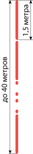 With this method of construction, the grounding electrode of the required length (depth) is a prefabricated structure of several short (1.5 meters) steel pins with small transverse dimensions (diameter less than 20 mm) with a zinc or copper coating, which are connected in series one after the other. a friend . For deepening using conventional household electric jackhammer with sufficient impact energy.
As in the case of the “casing” (Section G2 ) - a large area of contact of the grounding conductor with the ground is achieved by a large length (depth) of the electrode. Due to the achievement of the deep layers of soil, in most cases having less electrical resistivity, this method has greater efficiency (less ground resistance).
Connecting pins to each other can be done in several ways:
- “Blind hole + thorn” . On one side of the pin there is a blind hole 50-70 mm deep, and on the other side there is a spike 50-70 mm long, having a diameter slightly larger than the groove. When mounting the spike is pressed into the hole.

- “Blind hole + pin + blind hole” . The pin on both sides has a blind hole 50-70 mm deep. The pin length 100-140 mm is used as a separate additional part. During installation, it is inserted between the pins and pressed into both holes.
It is considered a very unreliable method of connection.
- "Thread + coupling + thread" . The pin on both sides has a thread length of 50 mm. Coupling, pipe section with internal thread, is used as a separate additional part. During installation, it is screwed onto the recessed pin, after which the next pin is screwed into it.
As the long-term practice has shown, this is the most reliable method of connection, allowing to assemble precast grounding electrodes up to 40 meters deep with guaranteed preservation of the necessary electrical and anti-corrosion properties along all lengths.
This depth is a compromise between the maximum impact energy of the jackhammer, the friction force between the mounted electrode and the ground, the mechanical strength of the coupling (its cost). Without an increase in the impact energy, it is impossible for the electrode to become even deeper due to the friction force. With increasing impact energy, it is necessary to increase the strength of the coupling, which causes an increase in its cost.
D1.1. Solution features. Anti-corrosion properties.
D1.1.1. Versatility and ease of use
This solution can be called a “constructor”, because any necessary construction is assembled from unified elements. For example, a deep electrode at 30 meters.All parts have industrial production, which eliminates the need to “finish” something on the object. At the same time, they have the same quality and the same properties, which plays a role when carrying out a large amount of installation work on many similar objects, and also has a positive effect on the predictability of results.
The handling of pins is facilitated because They are only 1.5 meters long and weigh no more than 3 kilograms. This allows you to transport them in a small car.
D1.1.2. Long service life
Coating a steel pin with a layer of zinc or copper increases its service life up to several times (relative to the service life of a pin of the same size without coating).Methods of protecting steel from corrosion in coatings vary greatly due to the different participation of these metals in electrochemical reactions, which have the most destructive effect on the pin. Due to the difference in these reactions, the difference in production, the difference in the cost of production, there are constant disputes over which coating is still better.
Zinc coating
In the pair of “zinc-iron” zinc is a reducing / donor ( wiki ). Oxidized / corroded primarily zinc, thus protecting iron.
When all of its mass learns about the reaction (oxidizes), it begins to corrode steel.
Advantages:
- no need for mechanical protection of the coating during installation. Damage to the integrity of the coating does not lead to consequences, since zinc still protects the iron, being close.
- cheap, well-established and widespread production of galvanized products with a standard coating thickness of 5 to 30 microns (“hot” and “cold” galvanizing)
- corrosion protection of not only the pins, but also all metal structures in the zone of action. However, these steel structures often do not need such protection.
Disadvantages:
- a relatively small increase in the service life of the pin due to the small thickness of the coating - up to 15-25 years.
- A thick layer of zinc coating is expensive. In addition, it is very rare to find a production that has the technical capability for this.
- reduction of the life of the pins in the presence of a large number of metal structures located next to them
Copper coating
In the copper-iron pair, copper is an oxidizing agent, and iron is a reducing / donor ( wiki ). Iron is primarily oxidized / corroded by iron, thus protecting copper.
Strange ... we need the opposite action. But here lies the peculiarity of the electrochemical reaction: it is possible only in the presence of electrolyte / water. If iron is isolated from it, the reaction stops.
Therefore, the copper coating must be thick and uniform in order to prevent its deep damage during installation and thus prevent electrolyte / water from entering the iron.
At the same time, the softness / plasticity of pure copper has a positive effect: it greatly reduces the friction force when scratching, which does not allow the sharp element in the ground (for example, stone) to completely scratch the coating in depth to the steel core. The stone simply glides over the surface, removing a small outer layer. This behavior of copper can be compared with soap, used to remove a ring stuck on a finger.
Advantages:
- very long service life of copper-coated pin - up to 100 years (subject to the integrity of the coating)
Disadvantages:
- the need to create a coating of large thickness (200 microns) to protect it from deep damage during installation. This coating is more expensive thinner.
- expensive and rare production of copper-coated products with a large coating thickness
My subjective opinion
Once we add a coating to protect against corrosion, it should provide the longest service life at the same cost of production (in comparison with other options).
In this plane, I believe that the best choice are copper-clad pins, subject to the unconditional quality of the coating, expressed in:
- thickness not less than 200 microns
- high adhesion ( wiki ) ensuring the preservation of the protective layer when bending the pin (sometimes occurs during installation)
Moreover, copper-clad pins are much more profitable than galvanized due to the high prices for the manufacture of the latter, while striving to achieve a comparable service life.
Tests conducted by one of the laboratories experimentally showed that the service life of a copper-coated pin with a coating thickness of 250 microns in aggressive soil (acid or alkaline) is at least 30 years, and in ordinary loam it will reach 100 years.
Also known is a test conducted from 1910 to 1955 by the National Institute of Standards and Technology (The National Institute of Standards and Technology (NIST)). An extensive study of underground corrosion was carried out, during which 36,500 samples representing 333 varieties of ferrous and non-ferrous metals and protective materials were tested at 128 sites throughout the United States.
One of the results of this study was the fact that the ground pin, coated with 254 microns of copper, retains its technical characteristics for more than 40 years in most types of soil. And rod electrodes, coated with 99.06 microns of zinc, in the same soils can retain their qualities only for 10-15 years.
Underground corrosion (United States. National Bureau of Standards. Circular 579)
Posted by: Melvin Romanoff; Publisher: US Govt. Print. Off., 1957)
Separately, I want to note the use of stainless steel pins as a material. This material has excellent anti-corrosion properties combined with excellent mechanical properties to facilitate the production of parts. His only drawback is the high cost .
D1.1.3. The dependence of the decrease in earth resistance on the increase in the depth of the electrode
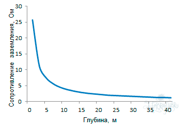
Because This solution has all the properties of the deep earthing remind its feature (from p. G2.1 ).When increasing the electrode depth, it is necessary to take into account that in a uniform ground the grounding resistance decreases not in proportion to this increase (more depth -> less decrease in resistance).
Therefore, in the absence of soil layers with a lower specific electrical resistance at a depth, it is worth considering the issue of increasing the number of electrodes, rather than increasing the depth of a single electrode. The solution of this issue will be affected by the cost of installing additional electrodes, and the availability of space for their placement.
In practice, in more than 70% of cases, the soil at a depth of more than 5 meters has several times less electrical resistivity than at the surface, due to greater humidity and density.
D1.1.4. Super compact
The small length of the pins and the use of a small-sized power tool allows you to install the deep earthing where before it was in principle impossible: at sites with the most constrained building construction and even in the basements of buildings. When working outside the building, a “patch” of earth with a diameter of 20 cm is enough to deepen the electrode.Such compactness is especially relevant in light of the need to obtain a large number of documents for opening coverage, carrying out work and the subsequent refining of the territory.
D1.1.5. No welding
All elements of the design are securely mated without electric or gas welding. Used either permanent or threaded connections. A special bolt clamp made of brass or stainless steel is used to attach the grounding conductor to the mounted electrode.D1.2. Calculation of the received grounding resistance
The calculation almost completely repeats the calculation of a single electrode from Section G2.2. with the exception of transverse dimensions - with modular grounding the diameter of the electrode does not exceed 20 mmOn the example of a thirty- meter composite electrode of copper-plated pins with a diameter of 14 mm , mounted in a ditch with a depth of 0.5 meters . The soil in which this electrode will be mounted will be, to simplify the calculation, homogeneous loam, common to Russia, with a specific electrical resistance of 100 Ohm * m .R1 will be 4.7 Ohm (at p = 100 Ohm * m, L = 30 m, d = 0.014 m (14 mm), T = 15.5 m (T is the distance from the upper ground level to the middle of the recessed electrode) ).
The calculation is carried out in 1 stage.
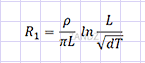
The grounding resistance of a single vertical grounding electrode is calculated by the formula:
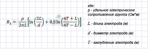
This result is worse than that of an electrode having a diameter of 100 mm, but I note that a decrease in the diameter of the electrode by 7 times (700%) caused an increase in the grounding resistance of only 27%.
D1.3. Installation
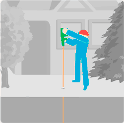
Installation of modular grounding is very easy and is available even to the girl.The pins are driven into the ground one by one with a jackhammer, gradually increasing the depth of the grounding electrode. Jackhammer is located above the pin.
The installer’s tasks: to keep the hammer evenly above the pin (not “on weight”, ie, the hammer with its weight presses not on the hands, but on the mounted pin) and to build up the electrode - to install the next pin above the already recessed one.
If the installation is performed outside the building, the installation of the modular grounding / earthing switch is made in a ditch of a small length and a depth of 0.5 meters, which also contains the grounding conductor (copper wire or traditional steel strip) that goes to the object (electrical panel).
If the installation is carried out inside the building (in the basement), then the installation of the earthing switch is made at the floor level. Next, the copper wire obtained earthing connects to the shield.
Both when using steel strip and when using copper wire, a bolt clamp in brass or stainless steel is mainly used to connect them to the pin.
Sometimes you can find a way to connect using exothermic welding (a mixture of combustible material with copper dust fills the point of contact between the conductor and the pin, welding them together). But this is exotic.
More information about mounting threaded pins can be found on YouTube ( link ).UPD: A jackhammer can be rented for a day (from 500-700 rubles) or purchased at almost any power tool store (from 9-10 thousand rubles).
D1.4. Advantages and disadvantages
Advantages:- simplicity and ease of installation. All operations are performed without serious physical labor by one person without much preparation.
- high efficiency grounding for low grounding resistance
- supercompact, allowing to mount the grounding on a very small platform or in the basement
- long service life of the grounding electrode (up to 100 years in loam)
- Seasonal Independence of grounding quality. In winter, due to freezing of the soil, the resistance of such a grounding conductor almost does not change due to being in the zone of freezing soil no more than 5-10% of the length of the electrode.
- no need welding. Structural elements mate securely without it.
Disadvantages:
- impossibility of mounting the electrode in stony ground. The nail does not hammer into the stone.
The pin due to the high mechanical strength of the structure can push back a small stone encountered in its path. Maybe, having bent away from the contact on a tangent with a large stone, continue the deepening not on the vertical axis. But hitting a large enough stone without the ability to deviate - it will rise. - relatively high price of copper-clad pins (about 380 rubles per square meter) and additional equipment for them. The price is much lower than the cost of drilling, but it is definitely higher than the price of black metal used in the construction of a traditional multielectrode earthing switch.
However, it is more objective to compare not the “bare” cost of materials, but the cost of all costs during the construction of the earthing switch. It often turns out that the total costs are comparable or even lower just at modular grounding (for example, due to the banal savings on the delivery of materials to an object).
D 2. Electrolytic grounding (for permafrost or stony ground)
D2.1. Solution features
D2.1.1. Easy to use in permafrost or stony ground
D2.1.2. Compactness
D2.1.3. Talik formation
D2.1.4. No weldingD2.2. Calculation of the received grounding resistance
D2.3. Installation
D2.4. Advantages and disadvantages
Let me remind you of the noted in paragraph G1.5. method sometimes used to significantly reduce grounding resistance .
Salinization of soil at the location of the electrodes by adding a large amount of sodium chloride salt to it. When it dissolves in the soil (leaching ( wiki )), the concentration of ions involved in charge transfer sharply increases, and hence its (soil) electrical resistance decreases.
With the undeniable positive advantage of this method, as well as its simplicity and cheapness - it has two huge drawbacks:
- due to the salt leaching from the ground (rain, spring snow melting), the ion concentration drops to its natural level in 2-3 years
- Salts cause severe corrosion of steel, destroying electrodes and grounding conductor in 3-5 years. These shortcomings threaten to restore the grounding almost from scratch.
Needed measures to counter these shortcomings and they became:
- constant maintenance of the concentration of ions in the soil. In other words, their replenishment with new portions.
- use in the construction of materials that are minimally exposed to salt, and less aggressive components of these salts
As a result, a solution was developed that was called “electrolytic grounding” (electrolyte - salt solution) .
An electrode of this type is a tube of short length (usually 2-3 meters) made of stainless steel, which has a perforation almost along its entire length. Inside this tube are granules (not powder) of a mixture of salts.
In addition to the usual NaCl, there are 3 more components in the mixture. The composition is supposedly a secret of the manufacturers, but we know how it happens :-)
Industrially produced two types of pipes. Vertically and horizontally (in the form of a rotated letter “G” - like this “I ___”.
Such an electrode is placed in the ground: vertical execution - in a pre-made well of the required depth (2.5 - 3.5 meters); horizontal execution - into a previously dug ditch 0.7 meters deep 2.5 meters long.

Moisture from the soil is absorbed by salts in the electrode and comes out in the form of a solution (electrolyte) into the same soil, impregnating it and causing a decrease in its specific electrical resistance.
Because of this, the grounding resistance of the electrode (pipe) placed in this ground is reduced.
Because a mixture of salts is in the granules and in its composition there is a special additive, it does not dissolve in its entirety in the springtime, when the soil is saturated with water. In this way, a long-term and uniform electrolyte output from the electrode is achieved, gradually increasing (and not just preserving) the concentration of ions in the surrounding soil. Usually, the factory “charging” of the electrode lasts for 15 years, after which repeated “refueling” is possible .
The use of a stainless steel pipe as a material and the use of a salt mixture less aggressive than NaCl ensure the service life of the “shell” of such an electrode for at least 50 years.
D2.1. Solution features
D2.1.1. Easy to use in permafrost or stony ground
The design of the electrolytic grounding electrode allows it to be used in “problem” soils.Permafrost soils are constantly (year-round for hundreds of years) frozen. Meet in the north of our country. The depth of freezing of such soil reaches 2 kilometers (near Yakutsk). Permafrost begins from 1-2 meters above ground level, i.e. from the depths that can not warm the sun in the summer.To install an electrode of this type in a horizontal version, only a shallow depth (0.7 meter) is needed, which is relatively easy to dig in both types of soil. Placing the electrode in the top layer of soil above the permafrost eliminates the effect of “pushing”.
Permafrost soil is very difficult for building earthing: it has a very high electrical resistance (100-300 times more loam) and has the property of “pushing” metal electrodes out of itself due to the effect of water expansion during freezing. This occurs after summer thawing of the soil (the transition of ground moisture into a liquid state) under these electrodes.
Stony soil containing a large number of stones ranging in size from a fist to meter-high boulders is no less difficult for the construction of earthing due to the fact that it is difficult to submerge electrodes in the usual way - stones interfere.

The small penetration of the electrode makes it possible to use it limitedly in the rock shoes - if there is at least a meter layer of loose (above the “impregnation” with the electrolyte) soil above the stone monolith.
D2.1.2. Compactness
Electrolytic grounding electrode is up to 12 times more efficient than a conventional steel electrode of the same size. This means a 12-fold reduction in the required number of grounding elements, and therefore the area occupied by them is significantly reduced.At the same time, the dependence of ground resistance on the season is very weakened due to a decrease in the freezing point of water with an increase in salt concentration in it to -5 degrees (the temperature of the usual soil under the snow cap). This removes the need to use additional grounding electrodes to compensate for the increase in resistance in winter.
D2.1.3. Talik formation
The property of the electrode to reduce the soil freezing temperature has a negative point. A talik zone ( wiki ) is formed near the electrode, which may pose a danger to the foundation of a nearby building or pavement. The talik zone on the ground surface is an oval measuring about 3x6 meters. Therefore, in the course of design work, it is necessary to take this into account and distance the electrodes from objects that may be damaged.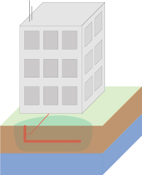
D2.1.4. No welding
A special bolt clamp made of brass or stainless steel is used to attach the grounding conductor to the mounted electrode.D2.2. Calculation of the received grounding resistance
I will give an example of calculating the grounding resistance of an electrode of horizontal execution, since This is the most common variant in practice, having a horizontal length of 2.4 meters and its diameter of 65 mm . The soil, as usual, will be a homogeneous loam with a specific electrical resistance of 100 Ohm * m .The grounding resistance of a single horizontal grounding electrode is calculated by the formula:
In the case of an electrolytic grounding electrode, a factor is added to the formula that describes the concentration of electrolyte in the soil around this electrode:
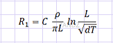
The coefficient varies from 0.5 to 0.05. Gradually, it decreases, because electrolyte penetrates the ground to a larger volume, while increasing its concentration. In ordinary soil, it is 0.125 after 1-2 months of salt leaching. The process can be accelerated by adding water to the electrode at the final stage of installation.
R1 will be 4.14 Ohms (at C = 0.125, p = 100 Ohm * m, L = 2.4 m, d = 0.065 m (65 mm), T = 0.6 m (T is the distance from the upper ground level to the middle of the recessed electrode) ).
Excellent result for a single earthing device with a size of only 2.4 meters!
But, as always, the payment for the result in the price of such an electrode ... What is lower in Section D2.4. (limitations).
D2.3. Installation
Installation of an electrolytic grounding electrode for horizontal execution is the simplest of all the methods I have encountered. In fact, this is a banal instillation of the electrode at a shallow depth.The ditch is 0.75 meters deep and 2.5 meters long. At the bottom of the electrode falls.Using the bolt clamp, the grounding conductor is connected. The ditch is buried.
Additionally, you can pour water into the mouth of the electrode 5 liters to speed up the leaching process.
D2.4. Advantages and disadvantages
Advantages:- simplicity and ease of installation
- very high grounding performance, providing low grounding resistance
- the compactness allowing to mount a grounding conductor on the small platform.
However, taking into account the negative features described in paragraph D2.1.3. - long service life of the grounding electrode (at least 50 years) when it is “refilled” with a mixture of salts.
The solution was originally created with this property. - very weak seasonal dependence of grounding quality
- no need welding. Structural elements mate securely without it.
Disadvantages:
- high price of the electrode (40-60 thousand rubles per electrode), which limits the widespread use.
It is recommended to use electrolytic grounding in permafrost or rocky soils, in which conventional construction methods do not allow to achieve the desired result or even more expensive. - the need to move away from the foundations of buildings and roads
That's all. Thanks for attention!Sorry for the large amount of information.
Questions can be asked in the comments or directly on my coordinates specified in the profile. I am always happy to help those who are interested in the best of my abilities and knowledge.
Feel free to :-) Remember: no stupid questions - there are stupid answers.
PS My knowledge in the field of protective devices and electrical networks is very poor and superficial. Please keep this in mind.
Alexey Rozhankov, specialist of the technical center " ZANDZ.ru "
In preparing this article, the following materials were used:
- Publications on the site " Grounding and lightning protection on ZANDZ.ru "
- Electrical Installation Rules (PUE), part 1.7 as amended by the seventh edition ( google )
- Instructions for lightning protection of buildings and structures RD 34.21.122-87 ( google )
- Technical Circular 11/2006 Association "Roselektromontazh" ( google )
- GOST R 50571.21-2000 (IEC 60364-5-548-96)
Grounding devices and systems for equalizing electrical potentials in electrical installations containing information-processing equipment ( google ) - Underground corrosion (United States. National Bureau of Standards. Circular 579)
Author: Melvin Romanoff; Publisher: US Govt. Print. Off., 1957) - Own experience and knowledge
Source: https://habr.com/ru/post/145125/
All Articles