Initial configuration of the Cisco Wi-Fi controller
So, it happened. You were brought to the table by a freshly purchased Cisco wi-fi controller, and a dozen new access points. What is it, why should I, how does it work? How can I install this controller in the network, and finally “distribute the file file correctly”? This will be discussed today.
Why do I need a controller? Without going into much detail, the access points and the controller together provide wireless clients access to the rest of the (wired) part of the network. Half of the tasks associated with access to the radio environment, generation of beacon frames, encryption, are performed by the access point itself. The other half, mainly association and authorization, is served by the controller. This is called Split-MAC architecture.
')
Access points are connected to the controller via the local switched network (of course, made by Cisco, although the CAPWAP interaction protocol is open). There may be up to hundreds of them per controller, depending on its performance. Several controllers can be combined into groups, while ensuring coordinated work of the controllers, and the points themselves, according to the general settings. The advantages of this approach are obvious: centralized management, flexibility of settings, fault tolerance, load balancing, intelligent functions like seamless roaming, frequency resource management, power, quality of service, authorization.
On access points connected to the controller, the so-called. "Lightweight" (lightweighted) works almost the same way IOS (AIR-LAP-xxx), as on conventional (standalone, AIR-AP-xxx). The difference is in the absence of the mode “conf t”, since the points are configured by the controller centrally. Firmware between standalone lightweighted can be manually changed "back and forth."
At the start, the access point searches for the best available controller according to a rather complicated scheme, authorizes, downloads the firmware (if required), settings, and starts serving clients. A control channel (UDP port 5246) and a data channel (UDP port 5247) are organized between the point and the controller. User data is encapsulated into UDP packets regardless of the client WLAN / VLAN number, which allows you to place access points anywhere on the network (on the access ports of the switches), and centrally manage security at the VLAN level on the controller side. For the case of “remote office”, where there is no controller, a mode with local switching of client traffic is provided.
Architecturally, the controller is a specialized computer (different hardware architecture and capacity, depending on the model) with a fairly old version of MontaVista Linux inside. Several modules have been added to the kernel, sometimes a hardware driver for hardware acceleration of encryption or packet forwarding. All actions associated with the life of the controller, executes a large monolithic process, designed as a user-application.
Having connected the controller to the power supply, COM-port (9600/8 / N / 1) and local network, the initial configuration is required. It's easy, if you understand what is being asked and why. Below is the procedure for initial configuration of the NME-AIR-WLC (module for the ISR router), in my case successfully virtualized and then running in a virtual machine:
Suspend the autoinstall feature. It allows the controller to automatically download a pre-configured config file via TFTP. Thus, you can deploy a lot of controllers in the network without having to manually configure each. Useful if you have a WCS control system.
Set the name of the controller (the one that is generated from the MAC address), the administrator's login and password:
Configure addressing management interface. This is a logical interface through which the controller “communicates” with the outside world (except for access points). The usual practice is that all the physical interfaces of the controller are combined into an EtherChannel group (you can do this later), and in such a common channel you configure how many logical interfaces are required, each in its own VLAN. In this example, a trunk port is created between the switch and the controller, and the service is carried out through VLAN 310. For the access port, or if you have a native VLAN, specify the number 0. The DHCP server address is needed to send client DHCP requests to the client if such will be configured. The controller will be a DHCP relay (although it can also act as a DHCP server).
All controllers, except the 5508 model, use a separate ap-manager logical interface to communicate with access points. You must configure its address, usually from the same network:
The last logical interface is virtual. It is used to send DHCP requests to clients, web authorization, roaming. It is assigned an address that is not used anywhere on the network and is not routable, usually 1.1.1.1. Attention: it must be the same for several controllers between which roaming clients are supposed.
For client roaming purposes, controllers are combined into mobility groups, the name of which is proposed to be set. It is also proposed to set the name of the group of controllers that collectively provide the control of the radio echo (frequency plan and power, rf group). Although it may be different groups by device set and name, here is the common name (you can change it later):
Wizard offers to create one wireless network (WLAN). I usually specify something here, anyway, then I delete this network, and create the correct one from the web interface.
The bridging mode of DHCP packets is exotic and is hardly applicable in practice.
You can enable wireless clients that have an IP address statically assigned. Actually, this option enables ARP caching on the controller, which is useful.
For the purposes of client authorization (as well as access to the controller, and some specific others), an external RADIUS server can be used, which is more convenient to configure later via the web interface.
Each access point, and controller, have valid country codes in which they operate. In fact, the country code determines the allowed set of frequencies (channels) and limiting powers, which affects the operation of automatic frequency selection algorithms, etc. It is highly recommended that the list of country codes be uniformly configured throughout your network.
The controller suggests enabling 2.4 and 5 GHz networks (11b / g / n and 11a / n, respectively). In fact, this parameter is transmitted to the access points associated with the controller, on which the radio itself is installed. I advise you to turn on the radio via the web interface after all the other parameters are configured.
Request for the inclusion of useful algorithms for dynamic control of the frequency resource and power, as we said earlier.
The time settings (time server and static time / time zone) are important not only for the correctness of the tags in the log files, but also for the authorization of access points using certificates (they use CAPWAP based on DTLS based on certificates validity).
Finally, if you are ready, the controller saves the configuration, and restarts:
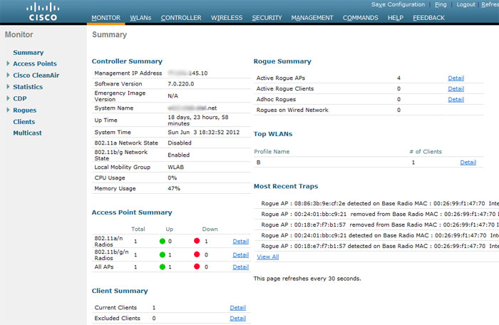
Everything, now the device can be configured through the web-based management interface, accessible in a couple of minutes at: https: //xx.xx.145.10 . To avoid unnecessary questions about the validity of the site, the controller can later be issued a certificate for SSL.
Controllers can also be configured via the command line (console, telnet, ssh). From syntax, IOS CLI supporters will spit, and JunOS fans will be shocked. The command line, however, is very useful for debugs, without which you simply do not step on Cisco wireless systems.
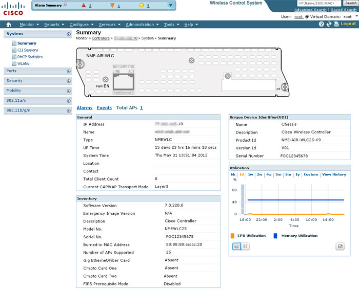
Now is the time to read the comprehensive controller setup guide , and rush into battle. If you havehands and a file of sufficient funds, you can think about the implementation of an extremely convenient centralized management tool for the NCS / WCS wireless network, a screenshot of which is shown below:
The next step is to install and connect access points .
PS The author is in no way affiliated with Cisco Systems, does not sell or buy anything.
Why do I need a controller? Without going into much detail, the access points and the controller together provide wireless clients access to the rest of the (wired) part of the network. Half of the tasks associated with access to the radio environment, generation of beacon frames, encryption, are performed by the access point itself. The other half, mainly association and authorization, is served by the controller. This is called Split-MAC architecture.
')
Access points are connected to the controller via the local switched network (of course, made by Cisco, although the CAPWAP interaction protocol is open). There may be up to hundreds of them per controller, depending on its performance. Several controllers can be combined into groups, while ensuring coordinated work of the controllers, and the points themselves, according to the general settings. The advantages of this approach are obvious: centralized management, flexibility of settings, fault tolerance, load balancing, intelligent functions like seamless roaming, frequency resource management, power, quality of service, authorization.
On access points connected to the controller, the so-called. "Lightweight" (lightweighted) works almost the same way IOS (AIR-LAP-xxx), as on conventional (standalone, AIR-AP-xxx). The difference is in the absence of the mode “conf t”, since the points are configured by the controller centrally. Firmware between standalone lightweighted can be manually changed "back and forth."
At the start, the access point searches for the best available controller according to a rather complicated scheme, authorizes, downloads the firmware (if required), settings, and starts serving clients. A control channel (UDP port 5246) and a data channel (UDP port 5247) are organized between the point and the controller. User data is encapsulated into UDP packets regardless of the client WLAN / VLAN number, which allows you to place access points anywhere on the network (on the access ports of the switches), and centrally manage security at the VLAN level on the controller side. For the case of “remote office”, where there is no controller, a mode with local switching of client traffic is provided.
Architecturally, the controller is a specialized computer (different hardware architecture and capacity, depending on the model) with a fairly old version of MontaVista Linux inside. Several modules have been added to the kernel, sometimes a hardware driver for hardware acceleration of encryption or packet forwarding. All actions associated with the life of the controller, executes a large monolithic process, designed as a user-application.
Having connected the controller to the power supply, COM-port (9600/8 / N / 1) and local network, the initial configuration is required. It's easy, if you understand what is being asked and why. Below is the procedure for initial configuration of the NME-AIR-WLC (module for the ISR router), in my case successfully virtualized and then running in a virtual machine:
Cryptographic library self-test....passed!
XML config selected
Validating XML configuration
Cisco is a trademark of Cisco Systems, Inc.
Software Copyright Cisco Systems, Inc. All rights reserved.

Cisco AireOS Version 7.0.220.0
Initializing OS Services: ok
Initializing Serial Services: ok
Initializing Network Services: ok
Starting ARP Services: ok
Starting Trap Manager: ok
Starting Network Interface Management Services: ok
Starting System Services: ok
Starting Fastpath Hardware Acceleration: ok
Starting Switching Services: ok
Starting QoS Services: ok
Starting Policy Manager: ok
Starting Data Transport Link Layer: ok
Starting Access Control List Services: ok
Starting System Interfaces: ok
Starting Client Troubleshooting Service: ok
Starting Management Frame Protection: ok
Starting Certificate Database: ok
Starting VPN Services: ok
Starting LWAPP: ok
Starting CAPWAP: ok
Starting LOCP: ok
Starting Security Services: ok
Starting Policy Manager: ok
Starting Authentication Engine: ok
Starting Mobility Management: ok
Starting Virtual AP Services: ok
Starting AireWave Director: ok
Starting Network Time Services: ok
Starting Cisco Discovery Protocol: ok
Starting Broadcast Services: ok
Starting Logging Services: ok
Starting DHCP Server: ok
Starting IDS Signature Manager: ok
Starting RFID Tag Tracking: ok
Starting RBCP: ok
Starting Mesh Services: ok
Starting TSM: ok
Starting CIDS Services: ok
Starting Ethernet-over-IP: ok
Starting DTLS server: enabled in CAPWAP
Starting CleanAir: ok
Starting WIPS: ok
Starting SSHPM LSC PROV LIST: ok
Starting RRC Services: ok
Starting FMC HS: ok
Starting Management Services:
Web Server: ok
CLI: ok
Secure Web: Web Authentication Certificate not found (error). If you cannot access management interface via HTTPS please reconfig
Secure Web: Web Authentication Certificate not found (error). If you cannot access management interface via HTTPS please reconfigure Virtual Interface.

(Cisco Controller)

Welcome to the Cisco Wizard Configuration Tool
Use the '-' character to backup
Suspend the autoinstall feature. It allows the controller to automatically download a pre-configured config file via TFTP. Thus, you can deploy a lot of controllers in the network without having to manually configure each. Useful if you have a WCS control system.
Would you like to terminate autoinstall? [yes]: yes
AUTO-INSTALL: process terminated -- no configuration loaded
Set the name of the controller (the one that is generated from the MAC address), the administrator's login and password:
System Name [Cisco_bb:bb:40] (31 characters max): wlc4...net
Enter Administrative User Name (24 characters max): anton
Enter Administrative Password (3 to 24 characters): *********
Re-enter Administrative Password : *********
Configure addressing management interface. This is a logical interface through which the controller “communicates” with the outside world (except for access points). The usual practice is that all the physical interfaces of the controller are combined into an EtherChannel group (you can do this later), and in such a common channel you configure how many logical interfaces are required, each in its own VLAN. In this example, a trunk port is created between the switch and the controller, and the service is carried out through VLAN 310. For the access port, or if you have a native VLAN, specify the number 0. The DHCP server address is needed to send client DHCP requests to the client if such will be configured. The controller will be a DHCP relay (although it can also act as a DHCP server).
Management Interface IP Address: xx.xx.145.10
Management Interface Netmask: 255.255.255.128
Management Interface Default Router: xx.xx.145.1
Management Interface VLAN Identifier (0 = untagged): 310
Management Interface Port Num [1]:
Management Interface DHCP Server IP Address: xx.xx.145.9
All controllers, except the 5508 model, use a separate ap-manager logical interface to communicate with access points. You must configure its address, usually from the same network:
AP Manager Interface IP Address: xx.xx.145.14
AP-Manager is on Management subnet, using same values
AP Manager Interface DHCP Server (xx.xx.145.9):
The last logical interface is virtual. It is used to send DHCP requests to clients, web authorization, roaming. It is assigned an address that is not used anywhere on the network and is not routable, usually 1.1.1.1. Attention: it must be the same for several controllers between which roaming clients are supposed.
Virtual Gateway IP Address: 1.1.1.1
For client roaming purposes, controllers are combined into mobility groups, the name of which is proposed to be set. It is also proposed to set the name of the group of controllers that collectively provide the control of the radio echo (frequency plan and power, rf group). Although it may be different groups by device set and name, here is the common name (you can change it later):
Mobility/RF Group Name: WLAB
Wizard offers to create one wireless network (WLAN). I usually specify something here, anyway, then I delete this network, and create the correct one from the web interface.
Network Name (SSID): test
The bridging mode of DHCP packets is exotic and is hardly applicable in practice.
Configure DHCP Bridging Mode [yes][NO]:
You can enable wireless clients that have an IP address statically assigned. Actually, this option enables ARP caching on the controller, which is useful.
Allow Static IP Addresses [YES][no]:
For the purposes of client authorization (as well as access to the controller, and some specific others), an external RADIUS server can be used, which is more convenient to configure later via the web interface.
Configure a RADIUS Server now? [YES][no]: no
Warning! The default WLAN security policy requires a RADIUS server.
Please see documentation for more details.
Each access point, and controller, have valid country codes in which they operate. In fact, the country code determines the allowed set of frequencies (channels) and limiting powers, which affects the operation of automatic frequency selection algorithms, etc. It is highly recommended that the list of country codes be uniformly configured throughout your network.
Enter Country Code list (enter 'help' for a list of countries) [US]: RU
The controller suggests enabling 2.4 and 5 GHz networks (11b / g / n and 11a / n, respectively). In fact, this parameter is transmitted to the access points associated with the controller, on which the radio itself is installed. I advise you to turn on the radio via the web interface after all the other parameters are configured.
Enable 802.11b Network [YES][no]: no
Enable 802.11a Network [YES][no]: no
Request for the inclusion of useful algorithms for dynamic control of the frequency resource and power, as we said earlier.
Enable Auto-RF [YES][no]:
The time settings (time server and static time / time zone) are important not only for the correctness of the tags in the log files, but also for the authorization of access points using certificates (they use CAPWAP based on DTLS based on certificates validity).
Configure a NTP server now? [YES][no]: no
Configure the system time now? [YES][no]: no

Warning! No AP will come up unless the time is set.
Please see documentation for more details.
Finally, if you are ready, the controller saves the configuration, and restarts:
Configuration correct? If yes, system will save it and reset. [yes][NO]: yes

Configuration saved!
Resetting system with new configuration...
Everything, now the device can be configured through the web-based management interface, accessible in a couple of minutes at: https: //xx.xx.145.10 . To avoid unnecessary questions about the validity of the site, the controller can later be issued a certificate for SSL.
Controllers can also be configured via the command line (console, telnet, ssh). From syntax, IOS CLI supporters will spit, and JunOS fans will be shocked. The command line, however, is very useful for debugs, without which you simply do not step on Cisco wireless systems.
Now is the time to read the comprehensive controller setup guide , and rush into battle. If you have
The next step is to install and connect access points .
PS The author is in no way affiliated with Cisco Systems, does not sell or buy anything.
Source: https://habr.com/ru/post/145082/
All Articles