Grounding What it is and how to do it (part 2)

1 part. Grounding
(general information, terms and definitions)
2 part. Traditional construction methods for grounding devices
(description, calculation, installation)
3 part. Modern methods of building grounding devices
(description, calculation, installation)
2 part. Traditional methods of building grounding devices (description, calculation, installation)
In this part I will talk about traditional / classical methods of building earthing, used from about the beginning of the twentieth century.
')
G. The main methods of construction
G1. Several short electrodes (“corner and sledgehammer”)
G1.1. Solution features
G1.1.1. Soil freezing in winterG1.2. Calculation of the resulting grounding resistance and the required number of grounding electrodes
G1.1.2. Mutual “shielding” / “shading” of electrodes
G1.3. Installation
G1.4. Advantages and disadvantages
G1.5. Reducing the number of electrodes
R2. Single Deep Electrode (“Casing”)
G2.1. Solution feature
G2.2. Calculation of the received grounding resistance
G2.3. Installation
G2.4. Advantages and disadvantages
G. The main methods of construction
I recall in the last part I focused on the general approach ...
In the construction of earthing most often used vertical grounding electrodes. This is due to the fact that horizontal electrodes are difficult to be buried to a greater depth, and when these electrodes are shallow, they greatly increase the grounding resistance (deterioration of the main characteristic) in winter due to the freezing of the upper soil layer, leading to a large increase in its specific electrical resistance.
Steel tubes, pins / rods, angles, etc. are almost always chosen as vertical electrodes. standard rolled products having a greater length (more than 1 meter) with relatively small transverse dimensions. This choice is associated with the possibility of easy penetration of such elements into the ground, unlike, for example, from a flat sheet.
There are two main traditional methods / solutions for building grounding electrodes . Both are based on the use of vertical grounding electrodes.
G1. Several short electrodes (“corner and sledgehammer”)
With this approach, small (2-3 meters) steel corners / pins are used as grounding electrodes. To create a grounding conductor, they are joined together around the soil surface with a steel strip by welding it to these elements with electric or gas welding.The penetration of the electrodes into the ground is done by banal hammering them with a sledgehammer, which is in the hands of a physically strong and durable installer. Therefore, this solution is commonly used under the code name "corner and sledgehammer."

A large contact area of the grounding conductor with the ground ( that 's what I mean) is achieved by a large number of electrodes ( multielectrode grounding ). It is very difficult to increase the depth of the electrodes (an alternative way to increase the contact area), since with increasing depth, the friction force between the mounted electrode and the ground increases, and the weight of the sledge hammer and the fitter's forces have a limit.
When choosing corners / pins and other suitable metal, it is necessary to take into account their corrosion resistance and the ability to pass large currents through themselves for some time without melting.
The minimum allowed lateral dimensions (cross-sections) of grounding electrodes are described in table 1.7.4 of the OES, but in recent years corrected and augmented values from table 1 of tech-circular 11 from 2006 of the RosElectroMontazh Association ( sources ) are more often used.
In particular:
- for a corner or rectangular profile (strip) of black steel, the cross section must be at least 150 mm 2 with a minimum wall thickness of 5 mm
- for a round rod made of black steel the minimum diameter should be 18 mm
- for black steel pipe profiles, the minimum diameter should be 32 mm with a minimum wall thickness of at least 3.5 mm
G1.1. Solution features
When increasing the number of electrodes, it is necessary to take into account some features.G1.1.1. Soil freezing in winter
In winter, due to the freezing of the soil to a depth in which there is half the length of the electrodes (and this is up to 2 meters), the resistance of such a grounding plane increases. To compensate for this increase (to maintain a satisfactory grounding quality), the earthing switch is made with a sufficient “margin” of electrodes. For example, for three-meter electrodes, a twofold increase in the number is necessary.G1.1.2. Mutual “shielding” / “shading” of electrodes
In addition, by increasing the number of electrodes, it is necessary to compensate for the increase in the number of electrodes :-) This negative point is so-called. “Shielding” / “shading” occurs when using multiple grounding electrodes and does not allow nearby electrodes to fully “dissipate” the current into the surrounding ground. It is expressed in terms of the utilization of the conductivity of the ground (reference to a third-party site).For example: ten electrodes with a depth of 3 meters, located in a line at a distance of 3 meters (ie, at a distance = their depth) from each other, “work” at 60% of their maximum efficiency.
Ten of the same electrodes, located at a distance of 6 meters (ie, at a distance = its double depth) from each other, “work” at 75% of their maximum efficiency.
One hundred percent efficiency is achieved by moving the electrodes to distances of about 30 meters (10 of their depths), which in practice is never used in order to strive for adequate compactness and the cost of installing a grounding device.
G1.2. Calculation of the resulting grounding resistance and the required number of grounding electrodes
I will describe the calculations using the example of the ten most commonly used three-meter electrodes in the form of a steel equal angle steel shelf 50 mm wide , mounted at a distance of 3 meters from each other in a ditch 0.5 meters deep (in section G1.3. Explanation "why is that"). The soil in which these electrodes will be mounted will be loam, common to Russia, with a specific electrical resistance of 100 ohm * m .The calculations are not complicated and are carried out in 3 stages.
Received grounding resistance
Stage 1. First you need to calculate the grounding resistance of a single grounding electrode.
The grounding resistance of a single vertical grounding electrode is calculated by the formula:
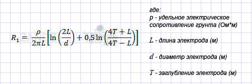
R1 will be 27.8 ohms
(at p = 100 Ω * m, L = 3 m, d = 0.05 m (50 mm; for flat electrodes, diameter is their width), T = 2 m (T is the distance from the upper ground level to the middle of the buried electrode)) .
Stage 2 The total resistance of several electrodes in ideal conditions will be less than the ground resistance of one electrode as many times as there will be electrodes.
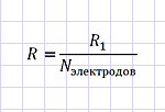
For ten electrodes, the total resistance will be 10 times less and will be 2.78 ohms .
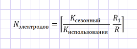
Stage 3 “Compensation”.
The seasonal coefficient (increase in grounding resistance in the ground frozen in winter) for such electrodes will be equal to 2 ( whence it).
The utilization of the conductivity of the electrodes will be equal to 0.6 , since the distance between the electrodes will be 3 meters (i.e. equal to the depth of the electrode), and their number will be 10 pieces ( from where it is).
Both factors increase grounding resistance.

The total total ground resistance of the above 10 electrodes will be 5.56 ohms in summer and 9.27 ohms in winter.
The required number of grounding electrodes
Imagine that our task is to ground the telecommunications equipment and for this you need to get a ground with a resistance of not more than 4 Ohms .
Stage 1. All repeats. Calculate the grounding resistance of a single / single grounding electrode.
R1 will be 27.8 ohms .
Stage 2 The number of electrodes in ideal conditions directly depends on the required grounding resistance with rounding up ("ceiling").

To achieve 4 ohms, the number of electrodes will be 7 pieces (rounding 6.95).
Stage 3 “Compensation”.
The seasonal coefficient (increase in grounding resistance in the ground frozen in winter) for such electrodes will be equal to 2 .
The utilization rate of the conductivity of the electrodes will depend on the calculated number of electrodes — it cannot be selected in advance. However, you can estimate the worst option and, assuming that there will be more than 20 electrodes, take the value of 0.5 for the calculation.
Both factors increase the required number of grounding electrodes.
The total required number of the above grounding electrodes will be equal to 28 pieces (rounding of 27.8). The coincidence with the grounding resistance of one electrode is random.
G1.3. Installation
The installation of the multielectrode earthing described above looks like this.- A ditch 84 meters long (28 electrodes per 3 meters) with a depth of 0.5-0.7 meters is digging from the place where the grounding conductor is inserted into the building / object along the perimeter / contour of this building along its walls at a distance of 1 meter.
- At a distance of not less than 3 meters from each other, the dimpled steel corners or sections of reinforcement 3 meters long in the amount of 28 pieces are hammered into this ditch with a sledgehammer.
- After driving all the electrodes into the ditch, the grounding conductor is laid from the entrance to the building (where the electrical panel is located) to the farthest electrode. Usually with this method, such a conductor is a steel strip of 4 * 50 mm.
- The strip is qualitatively (!) Long seam welded to the electrodes.
- The welding area is covered with a layer of bitumen or anti-corrosion paint, because It has a tendency to rapid corrosion in the soil.
- Ditch falls asleep.
- Outside or inside the building, a transition is made from the steel strip to the copper wire connected to the electrical panel.
For low power, it is usually done like this: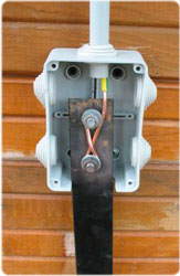
A recess of 0.5-0.7 meters (ditch) is necessary for the mechanical and weather insulation of the conductor (strip) and the tips of the electrodes. For example, in order not to damage them while digging the soil for the flower bed and so that the steel gets less wet during the rain (this allows reducing its corrosion, and thus increasing the service life).
Mutual distance between the electrodes of at least 3 meters is some measure to counteract the effect of “shielding” / “shading” the electrodes from each other.
The use of welding to connect elements of black steel is strongly recommended by EMP (Section 1.7.139).
Materials used:
- steel corner 50 mm wide and wall thickness 5 mm = 84 meters
- or pieces of steel smooth reinforcement with a diameter of 18 mm = 84 meters
- steel strip 4 * 50 mm = about 85 meters
- bitumen or anticorrosion paint
Used tool:
- shovel
- sledgehammer heavier (4-5 kg)
- welding machine
Resources used:
- strong and hardy fitter
- welder fitter
G1.4. Advantages and disadvantages
Advantages:- simplicity
- low cost of materials and installation
- availability of materials and installation
Disadvantages:
- high cost of delivery of material to the object (in the passenger car is not put because of the size and weight of materials)
- the need for a large amount of brute force (digging a ditch, waving a sledgehammer)
- welding is required, which means a welding machine and a person with welding skills. The situation is exacerbated by the absence of electricity at the facility.
- a large area occupied by the grounding: often several tens of meters near the building (ten 3-meter electrodes should be located in a 27-meter long ditch)
- short electrode life of 5-15 years (especially in soils with high groundwater). The increase in transverse dimensions (thickness of steel) is fraught with an increase in the complexity of installation.
- inconvenient installation, because when using even 2-meter electrodes at the beginning of driving it is necessary to stand on some kind of bench / ladder and “wave a sledge hammer” from it
- impossibility of mounting in stony ground
G1.5. Reducing the number of electrodes
Sometimes, together with this solution, a method is used to drastically reduce the specific electrical resistance of the soil, which reduces the number of grounding electrodes by a factor of 2-3 while maintaining the resulting grounding resistance. In other words - this method can significantly reduce the grounding resistance.We are talking about salinization of the soil in the place of placement of the electrodes by adding a large amount of sodium chloride salt to it (on average, 5 kilograms per meter of ditch length into which installation is carried out). When it dissolves in the soil (leaching ( wiki )), the concentration of ions involved in charge transfer sharply increases, and hence its (soil) electrical resistance decreases.
With the indisputable positive advantage of this method, as well as its simplicity and cheapness - it has two huge drawbacks that threaten to restore the grounding almost from scratch:
- due to the washing out of salt from the ground (rain, spring snow melting), the ion concentration drops to its natural level in 1-3 years
- salt causes severe corrosion of steel, destroying electrodes and grounding conductor in 2-3 years
R2. Single Deep Electrode (“Casing”)
G2.1. Solution features
G2.2. Calculation of the received grounding resistance
G2.3. Installation
G2.4. Advantages and disadvantages
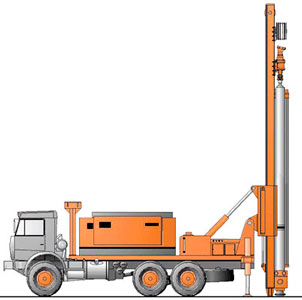
With this approach, the grounding is a deep electrode (most often a single) in the form of a steel pipe placed in a hole drilled in the ground. Drilling and placement in the hole of the pipe is performed by a special machine - a drilling rig (usually on the basis of a truck).
A large contact area of the grounding conductor with the ground ( that 's what I mean) is achieved by a large length (or rather, depth) of the electrode. In addition, due to the achievement of deep soil layers, in most cases having a lower electrical resistivity, this method has greater efficiency (lower grounding resistance) than the first method - with the same total length of the electrodes.
G2.1. Solution feature
When increasing the electrode depth, it is necessary to take into account that in a uniform ground the grounding resistance decreases not in proportion to this increase (more depth -> less decrease in resistance).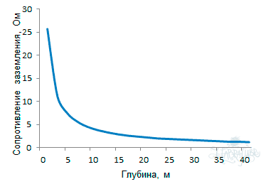
Therefore, in the absence of soil layers with a lower specific electrical resistance at a depth, it is worth considering the issue of increasing the number of electrodes, rather than increasing the depth of a single electrode. The solution of this issue will be affected by the cost of installing additional electrodes, and the availability of space for their placement.
But let me remind you (the original ): ... in practice, in more than 70% of cases, the soil at a depth of more than 5 meters has several times lower electrical resistivity than at the surface, due to greater humidity and density.
G2.2. Calculation of the received grounding resistance
I will describe the calculations on the example of a single thirty- meter electrode in the form of a steel pipe with a diameter of 100 mm , mounted in a ditch with a depth of 0.5 meters . The soil in which this electrode will be mounted will be, to simplify the calculation, homogeneous loam, common to Russia, with a specific electrical resistance of 100 Ohm * m .The calculation is carried out in 1 stage.
The grounding resistance of a single vertical grounding electrode is calculated by the formula:
R1 will be 3.7 ohms
(at p = 100 Ω * m, L = 30 m, d = 0.1 m (100 mm), T = 15.5 m (T is the distance from the upper level of the ground to the middle of the buried electrode)).
Compare with the result in Section G1.2 . Even under the condition of homogeneous soil, a single deep earthing turns out to be much more efficient than a multielectrode, which will affect the huge difference in the area occupied by this earthing on the surface.
But in this “euphoria” we should not forget about the cost of drilling, as I will mention below in Section G2.4. (“ Disadvantages ”).
G2.3. Installation
In practice, mounting such a grounding switch is somewhat simpler than mounting a multielectrode grounding switch from the first solution ( 1 ).- From the place of entry of the grounding conductor into the building / object at a distance of 3 meters (for safe access of the installation) a ditch with a length of 3-4 meters and a depth of 0.5-0.7 meters is digging in the direction perpendicular to the wall.
- The drilling rig produces drilling and electrode installation (“casing”).
- The grounding conductor is laid in the ditch from the entrance to the building (where the electrical panel is located) to the electrode. Usually with this method, such a conductor is a steel strip of 4 * 50 mm.
- The strip is qualitatively (!) Long welded to the electrode-pipe.
- The welding area is covered with a layer of bitumen or anti-corrosion paint, because It has a tendency to rapid corrosion in the soil.
- Ditch falls asleep.
- Outside or inside the building, a transition is made from the steel strip to the copper wire connected to the electrical panel. For example, as described in Section G1.3.
Materials used:
- steel pipe with a diameter of 100-200 mm with a wall thickness of 3.5-5 mm = 30 meters
- steel strip 4 * 50 mm = about 5 meters
- bitumen or anticorrosion paint
Used tool:
- drilling rig
- shovel
- welding machine
Resources used:
- welder fitter
G2.4. Advantages and disadvantages
Advantages:- high efficiency
- compactness, since no need to “fence” a lot of electrodes
- Seasonal Independence of grounding quality. In winter, due to freezing of the soil, the resistance of such a grounding conductor almost does not change due to being in the zone of freezing soil no more than 5-10% of the length of the electrode.
Disadvantages:
- the high cost of drilling (from 1500-2000 rubles per meter of drilling). The electrode given in the calculations (Section G2.2. ) Will cost 50-60 thousand rubles.
- ( like the first method ) requires welding, which means the welding machine and a person with the skills of a welder.
- ( like the first method ) a short electrode life of 5-15 years (especially in soils with high groundwater).
When using a thick-walled pipe it is possible to increase it to a longer period, but this causes an increase in the cost of this pipe.
Modern technologies
Tradition is past progress; future progress will become a tradition (Edouard Herriot)At the end of the twentieth century, a solution was developed that has the merits of both methods described above, with no inherent flaws.
In addition, the strong influence of soil salinization on the reduction of grounding resistance (Section G1.5. ) So attracted the attention of engineers that a “cure” was found for the shortcomings of this method - salt leaching out of the soil and electrode corrosion. It gave rise to a very interesting method of building a grounding conductor, applicable where simple metal electrodes are passed in - in permafrost as well as stony soils.
I will tell about them in the next , final part.
UPD: Advanced grounding in private homes
Those who live in private homes. / Cheerfully / Guys, do not panic because of the large number of grounding electrodes in the example. There I expected a device with a resistance of no more than 4 ohms. These are very strict requirements. To ground the power grid of a private house, it is sufficient to build a ground with a resistance of no more than 10 Ohms.That's why:
- This resistance is optimal from the point of view of the operation of protective automats.
- This resistance is enough to connect to the device interception rods (well, you never know - suddenly you want)
- This resistance is sufficient for guaranteed operation of SPDs, which are recommended to be placed in the shield at the entrance to the house. Surge protection devices are needed to protect your electrical equipment from impulse overvoltages when lightning strikes an overhead power line somewhere along the line from a transformer
10 ohms get a lot easier. These are only 10 electrodes. Half a day of normal work.
Alexey Rozhankov, specialist of the technical center " ZANDZ.ru "
In preparing this part, the following materials were used:
- Publications on the site “ Grounding on ZANDZ.ru ”
- Electrical Installation Rules (PUE), part 1.7 as amended by the seventh edition ( google )
- Technical Circular 11/2006 Association "Roselektromontazh" ( google )
- Own experience and knowledge
Source: https://habr.com/ru/post/144731/
All Articles