Using the Arduino UNO as a programmer
I had an idea to make an external interface for a water meter, so as not to climb into the basement to take readings. After some thoughts, I stopped at ATTiny2313A (it costs ~ 80p, and I don’t give the Arduino a price of ~ 1000r.) + Several resistors, buttons and a 7-segment indicator. But he stopped in front of the problem - unlike the Arduino, a programmer is needed here. Since I am not very keen on MK, I somehow don’t have any programmers. Arduino can theoretically be used in this capacity, but really I never did.
There are many articles on the Internet on this topic. But, at the moment, they are capable of confusing an unprepared person. The problem is the following - on previous versions of the Arduino (Duemilanove, Diecimila) there was an FT232RL chip, which is a USB -> UART converter. On Uno, this chip was removed, replacing it with Atmega8U2 (MK programmed for USB conversion -> Serial). Accordingly, most instructions do not suit us. I already thought that this idea was not feasible, but suddenly I found a suitable option. I will acquaint you with him. Let's start:
1. Open the Arduino IDE (I have this v1.0) and fill it with our Arduino Uno sketch called ArduinoISP (File -> Examples -> Arduino ISP). Please pay attention to the first lines of the file - it contains an important hint how to connect our programmer to the MC:
Actually, after this stage we already have an avrisp programmer, but our MK must also be connected to it.
')
2. We look in the datasheet to the desired MK (I have this ATTiny2313A) and look for pinout. In the next picture, I noted the legs of interest to us.
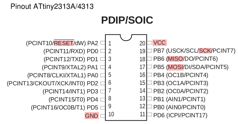
3. Now the most interesting stage has come - we connect our programmer to the MC. Actually, the wiring diagram is nothing complicated, but there is one trick - you need to connect a 10µF capacitor (uF) between the RESET and GND outputs of the Arduino. And the output "-" (marked with a white stripe) must be connected to GND. This trick will prevent the Arduino from rebooting when uploading firmware to the MC.

Connect the legs of the MK and Arduino pins in accordance with the functionality of pinout and sketch (Pin10 with leg PA2, Pin11 with leg PB5, etc.). Remember that VCC is power, and in our case + 5V. For the display, I chose the following LEDs:
9: Heartbeat - Green. Indicates that the programmer is working. In the process of idle constantly flashing.
8: Error - Red. Theoretically lights up when errors, but have never seen.
7: Programming - Blue. Flashes similarly to the Arduino RX / TX when flashing the firmware in the MC.
I hung them through 220 Ohm resistors.
The assembled scheme will look something like this:

4. Prepare the firmware for our MK. For testing, I decided to use the usual LED blink:
Compile to hex (tore the commands from some WinAVR Makefile):
And fill in the MK:
I want to draw attention to the limitation of the fill rate in 19200. Without this parameter, I have long tried to fill in something, but avrdude persistently returned errors like “programmer is not responding” or “not in sync”.
After that, you can connect the LED to the foot of the PB0 MK (via a resistor of course) and see how it flashes.
The source material for the article:
hlt.media.mit.edu/?p=1229
hlt.media.mit.edu/?p=1695
arduino.cc/en/Tutorial/ArduinoToBreadboard
iamsuhasm.wordpress.com/tutsproj/avr-gcc-tutorial
www.instructables.com/id/ATtiny-programmer-using-Arduino-ISP
There are many articles on the Internet on this topic. But, at the moment, they are capable of confusing an unprepared person. The problem is the following - on previous versions of the Arduino (Duemilanove, Diecimila) there was an FT232RL chip, which is a USB -> UART converter. On Uno, this chip was removed, replacing it with Atmega8U2 (MK programmed for USB conversion -> Serial). Accordingly, most instructions do not suit us. I already thought that this idea was not feasible, but suddenly I found a suitable option. I will acquaint you with him. Let's start:
1. Open the Arduino IDE (I have this v1.0) and fill it with our Arduino Uno sketch called ArduinoISP (File -> Examples -> Arduino ISP). Please pay attention to the first lines of the file - it contains an important hint how to connect our programmer to the MC:
// this sketch turns the Arduino into a AVRISP // using the following pins: // 10: slave reset // 11: MOSI // 12: MISO // 13: SCK // Put an LED (with resistor) on the following pins: // 9: Heartbeat - shows the programmer is running // 8: Error - Lights up if something goes wrong (use red if that makes sense) // 7: Programming - In communication with the slave Actually, after this stage we already have an avrisp programmer, but our MK must also be connected to it.
')
2. We look in the datasheet to the desired MK (I have this ATTiny2313A) and look for pinout. In the next picture, I noted the legs of interest to us.
3. Now the most interesting stage has come - we connect our programmer to the MC. Actually, the wiring diagram is nothing complicated, but there is one trick - you need to connect a 10µF capacitor (uF) between the RESET and GND outputs of the Arduino. And the output "-" (marked with a white stripe) must be connected to GND. This trick will prevent the Arduino from rebooting when uploading firmware to the MC.
Connect the legs of the MK and Arduino pins in accordance with the functionality of pinout and sketch (Pin10 with leg PA2, Pin11 with leg PB5, etc.). Remember that VCC is power, and in our case + 5V. For the display, I chose the following LEDs:
9: Heartbeat - Green. Indicates that the programmer is working. In the process of idle constantly flashing.
8: Error - Red. Theoretically lights up when errors, but have never seen.
7: Programming - Blue. Flashes similarly to the Arduino RX / TX when flashing the firmware in the MC.
I hung them through 220 Ohm resistors.
The assembled scheme will look something like this:
4. Prepare the firmware for our MK. For testing, I decided to use the usual LED blink:
#define F_CPU 1000000UL #include <avr/io.h> #include <util/delay.h> void init_io(void); void init_io(void) { DDRB = (1<< PB0); } int main(void) { init_io(); for (;;) { PORTB |= (1 << 0); _delay_ms(100); PORTB = 0; _delay_ms(100); } } Compile to hex (tore the commands from some WinAVR Makefile):
avr-gcc -c -mmcu=attiny2313 -I. -g -Os -funsigned-char -funsigned-bitfields -fpack-struct -fshort-enums -Wall -Wstrict-prototypes -Wa,-adhlns=blink_led.lst -std=gnu99 blink_led.c -o blink_led.o avr-gcc -mmcu=attiny2313 -I. -g -Os -funsigned-char -funsigned-bitfields -fpack-struct -fshort-enums -Wall -Wstrict-prototypes -Wa,-adhlns=blink_led.o -std=gnu99 blink_led.o --output blink_led.elf -Wl,-Map=blink_led.map,--cref -lm avr-objcopy -O ihex -R .eeprom blink_led.elf blink_led.hex And fill in the MK:
avrdude -p t2313 -P /dev/ttyACM0 -c avrisp -b 19200 -U flash:w:blink_led.hex I want to draw attention to the limitation of the fill rate in 19200. Without this parameter, I have long tried to fill in something, but avrdude persistently returned errors like “programmer is not responding” or “not in sync”.
After that, you can connect the LED to the foot of the PB0 MK (via a resistor of course) and see how it flashes.
The source material for the article:
hlt.media.mit.edu/?p=1229
hlt.media.mit.edu/?p=1695
arduino.cc/en/Tutorial/ArduinoToBreadboard
iamsuhasm.wordpress.com/tutsproj/avr-gcc-tutorial
www.instructables.com/id/ATtiny-programmer-using-Arduino-ISP
Source: https://habr.com/ru/post/144620/
All Articles