The history of the "compass of the 21st century"
Good time of day Habr!
And the story is such that a young specialist came to our company (I don’t say the name, as the company works with the State customer) (I’m not disclosing his name because he would be quickly taken otherwise) who will defend his master’s thesis this summer. And as a friendly person and colleague, I wanted to get to know him better. When we met, he revealed to me the secret of his dissertation (about which I will probably write later, when he successfully defends her), and in the dissertation there was an electronic compass module:
True, he is not at the final stage but, in my opinion, quite a worthy thing, because he can work autonomously. After a short conversation, we came to an agreement with him, and now I will describe his projects, which are quite a lot and they are applicable in everyday life.
So here we go (carefully many pictures)
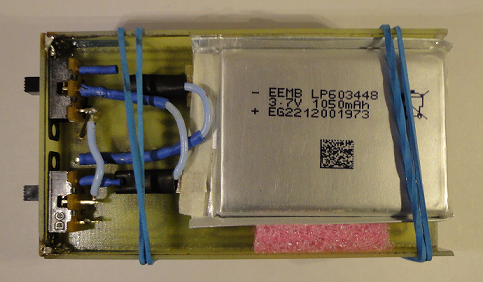
The idea of a compass is quite simple, based on the STM32F103CB microcontroller in the LQFP48 package
')
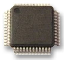
More details can be found here , the company STMicroelectronics, many of those who are familiar with this MK or viewed the information on the link will say that 72 MHz is a bit too much for such a simple device, I can give a price as an argument (the price ranges from 95 to 150 rubles), and In the plans of the author of the device “to finish” the program component to a pleasant look, which I understand and will require performance.
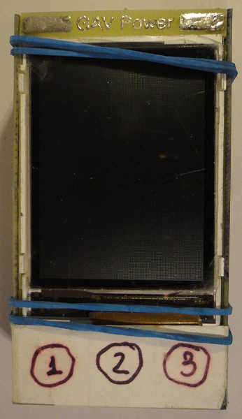
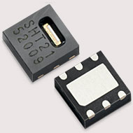
Also in the device there is a display from the phone SIEMENS S65 (if I’m really interested I can drop the datasheet on the mail to everyone), the temperature and humidity sensor SHT21 (if you’re interested in more details here ), which looks like this:
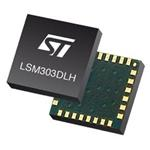
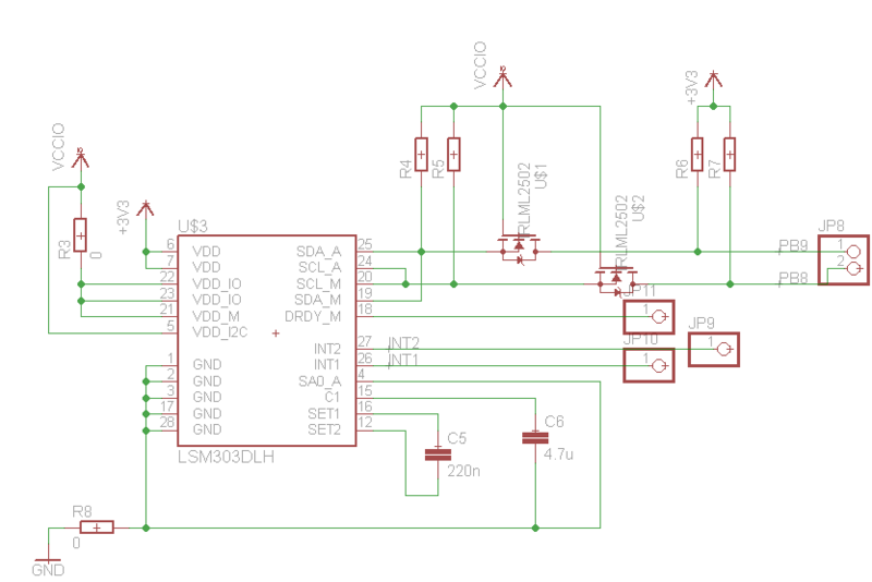
And just the accelerometer combined in one case with the LSM303DLH magnetometer (in more detail about it) from the same STMicroelectronics is responsible for the compass part; its appearance is not very remarkable, but in the article keep:
Well, it feeds all this with no name 1050 mAh battery, 3.7V external which looks like this:
More about the battery I have nothing to say.
I will not describe the binding of the main elements as there are datasheets, read the main points and interesting solutions in the next article, which I will write thoroughly after consulting the author of the “miracle”, and I almost forgot to have a keyboard
for three buttons, it is homemade and about it below, as well as two switches for power and backlight:
And so with the hardware, we figured out and now turn to the description of the manufacturing process
Here, the first item, as it should be, is the manufacture of a printed circuit board, of course darkness, and many use their favorites, so I’ll just say that he used a laser printer and an iron, the layout of the board and keyboard turned out to be:

(if someone needs this creation, then I will send you a PDF, of course, if the author will not mind)
As a result, the assembly should work according to the drawing as follows:
Well, we then saw that it came about like this.
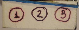
As you can see, the keyboard is a three grid made on the PCB and is an analogue of the buttons on the NES controller from Nintendo.
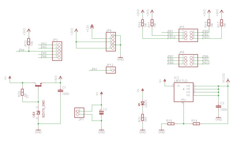
So now we solder the whole thing according to a scheme that turned out to be quite simple and consists of four small fragments (why I’m not combined into one I can’t answer because I don’t know the scheme editor):
Part containing port pinout pattern
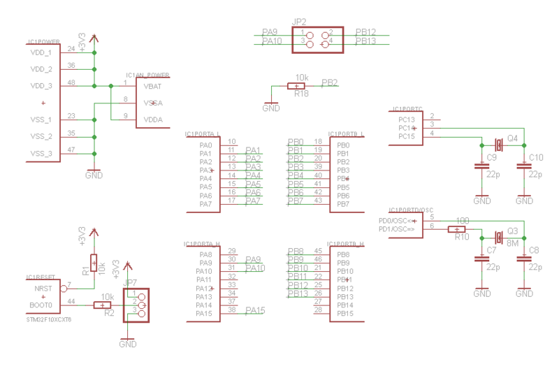
- part of the power system and connecting the displays and buttons
- part of the accelerometer connection
- and the pearl of the scheme (according to the author) is a step-up stabilizer

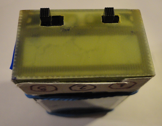
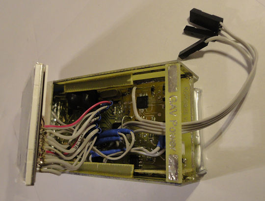
After the manipulations with an iron and a soldering iron, we get a practically finished product, the printed circuit board in this case is the body, although there are drawbacks to this design. For example, there is no back cover (as in the photo of the battery) and no display holder (as seen in the first photo in the post) and reliability is doubtful because of the “too” great durability of rubber bands for money. But I can assure you that the author is working to eliminate these shortcomings (and, more specifically, is looking for a simple and convenient body).
In the end, after the assembly, we get the device itself, but without the notorious gums, the result will be:
Now go to the software part
Here, according to the author, there is nothing complicated. But for me, to whom the programming of the MK has not resigned, it seems that everything is pretty difficult. And so we have in the project a module of the operating system (which is a task manager), you can see it here. The OS configuration file is here . The device initialization module is here .
And directly keyboard modules,
temperature and humidity sensor
accelerometer and magnetometer .
The device works smartly and because of the temporary lack of datasheet it can deal with keystroke combinations and their results only by looking at the source code, which, to my joy, is written in C (The assembler for some unknown reason causes my panic and I cannot understand the code). That's probably all that concerns the software part.
Go to testing
After switching on, the author’s name and OS version are shown on the screen (unfortunately I didn’t have time to catch it), although it doesn’t last that long, but the same information is also available while the device is working (I’ve erased the author’s name from conspiracy motives)

As you can see in the photo, the backlight is not at all superfluous, after turning it on, everything looks like this:
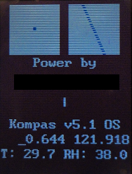
After the download, a favorite twist slash actually appears, prompting the user that the device is busy collecting and outputting data (although you can admit you can watch it for a long time, reflecting on the questions of being). Information from the accelerometer is displayed in the upper left corner (a dot on a white background moves along the white area indicating the slope), in the upper right corner there is information from a magnetometer that points north and south (although this is a line so far), the letter T denotes the temperature , RH relative humidity, numbers above temperature and humidity denote speed and movement. With a seemingly small battery capacity, it was enough for two days of intense tests (while it was charging directly, which I did not dare to do), due to the high sensitivity of the magnetometer, household appliances made their own, almost noticeable error, but somewhere in the forests of the Amazon or Siberia This problem will disappear by itself (Primus then hardly hurts). My personal verdict for this device is rather encouraging, rather than vice versa, the more the author modifies it in free time and as a result you can get a very useful gadget if you go on a hike without a modern smartphone (because there grows the likelihood of breaking it, running away from a bear) .
PS I apologize for the quality of the background in the photos, Ikea flashlight clips are obviously not enough for LightBox, but there were no others at hand. And also if there is a solution to demonstrate the source more compactly, I will be glad to help (thanks to G3kas , pel , Ruma7a , Ocelot , zona7o , morr , ertaquo for help in finding errors. Special Thanks to rmk for a detailed comment).
Source: https://habr.com/ru/post/144437/
All Articles