CISCO ACE. Part 2: balancing remote servers and applications
In the first part of CISCO ACE - application balancing, we plunged into the world of application balancing and network resources. We got acquainted with the characteristics, purpose and capabilities of the family of such devices. We considered the main implementation scenarios and the advantages that the use of balancers brings to us.
Probably many people caught themselves thinking that it was very expensive and did not see the benefits that the industrial balancer could provide to them. In the post I will pay attention to this particular moment and try to show that the service can be used by the majority.
')
In the first part, we looked at the case of balancing applications (balancing between servers) that are directly in the same data center. You can even say - in one L2 domain. Suppose that you are interested in the described benefits and want to get this service. In most public data centers, such equipment is not available, since the user needs to provide a server for 50-100 dollars per month. No one will let you into your corporate data center (not only the moment of physical location, but also the existing information security policy is taken into account).
The reasons given are not the same. If your project grows, then a good option is to place an additional server in another data center to increase service availability. And in the case of the increasing popularity of information raiding, the option is even necessary. Is this service for you? Yes, you can also use the existing functionality.
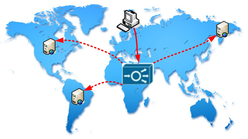
So, let us dwell on the fact that CISCO ACE (or any other decent balancer) is able to distribute the load not only between directly connected servers, but also between remote resources. This mode is called Routed One-Arm-Mode (or On-a-Stick).
The architecture of this mode is nothing special, just instead of Destination NAT (for farm hosts), the balancer produces additional Source NAT. Well, all other functions have not been canceled. I propose to consider an example demonstrating the possibilities.
In this case, all your traffic is sent to a virtual address (VIP). This address is assigned to the balancer. Processing requests, it redirects them to remote servers. All servers belong to the same structural group - the server farm. We will make a small adjustment. In many ways, it will repeat the structure discussed in the first article.
1. Create a server
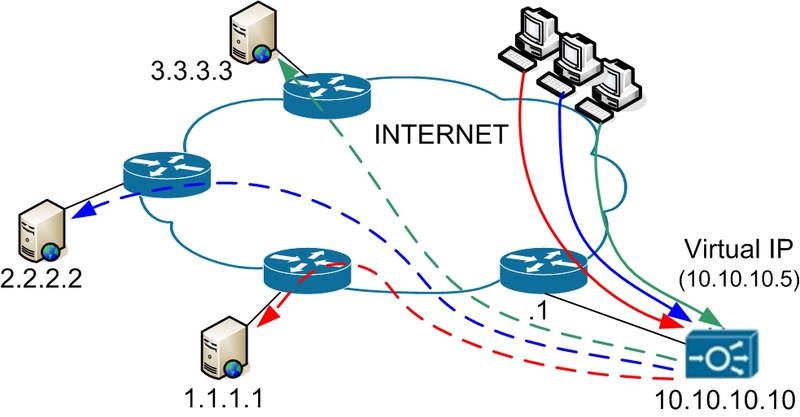
In our case there are three servers, with the addresses specified in the topology:
 rserver host SERVER-1 description SERVER-1 ip address 1.1.1.1 inservice
 rserver host SERVER-2 description SERVER-2 ip address 2.2.2.2 inservice
 rserver host SERVER-3 description SERVER-3 ip address 3.3.3.3 inservice
rserver host SERVER-1 description SERVER-1 ip address 1.1.1.1 inservice
rserver host SERVER-2 description SERVER-2 ip address 2.2.2.2 inservice
rserver host SERVER-3 description SERVER-3 ip address 3.3.3.3 inservice rserver host SERVER-1 description SERVER-1 ip address 1.1.1.1 inservice
rserver host SERVER-2 description SERVER-2 ip address 2.2.2.2 inservice
rserver host SERVER-3 description SERVER-3 ip address 3.3.3.3 inservice rserver host SERVER-1 description SERVER-1 ip address 1.1.1.1 inservice
rserver host SERVER-2 description SERVER-2 ip address 2.2.2.2 inservice
rserver host SERVER-3 description SERVER-3 ip address 3.3.3.3 inservice rserver host SERVER-1 description SERVER-1 ip address 1.1.1.1 inservice
rserver host SERVER-2 description SERVER-2 ip address 2.2.2.2 inservice
rserver host SERVER-3 description SERVER-3 ip address 3.3.3.3 inservice 2. We describe the rules for determining the availability of services (let there be a WEB server)
 probe http HTTP_PROBE interval 5 passdetect interval 10 passdetect count 2 request method head url /index.html expect status 200 210 header User-Agent header-value "LoadBalance"
 probe icmp ICMP_PROBE interval 10 passdetect interval 60 passdetect count 4 receive 1
probe http HTTP_PROBE interval 5 passdetect interval 10 passdetect count 2 request method head url /index.html expect status 200 210 header User-Agent header-value "LoadBalance"
probe icmp ICMP_PROBE interval 10 passdetect interval 60 passdetect count 4 receive 1 probe http HTTP_PROBE interval 5 passdetect interval 10 passdetect count 2 request method head url /index.html expect status 200 210 header User-Agent header-value "LoadBalance"
probe icmp ICMP_PROBE interval 10 passdetect interval 60 passdetect count 4 receive 1 What parameters and for what are intended - described in the first article .
3. Unite the device in the farm
serverfarm host FARM probe HTTP_PROBE probe ICMP_PROBE rserver SERVER-1 inservice rserver SERVER-2 inservice rserver SERVER-3 inservice 4. Create a virtual address and describe the balancing policy
Since the servers will receive requests directly from the balancer, the customer addresses for them will remain a mystery. You guessed what to do, add the X-Forwarded-For header.
 class-map match-all SERVER-VIP 2 match virtual-address 10.10.10.5 any

 policy-map type loadbalance first-match LB-POLICY class class-default serverfarm FARM insert-http X-Forwarded-For header-value "%is"
class-map match-all SERVER-VIP 2 match virtual-address 10.10.10.5 any
policy-map type loadbalance first-match LB-POLICY class class-default serverfarm FARM insert-http X-Forwarded-For header-value "%is" class-map match-all SERVER-VIP 2 match virtual-address 10.10.10.5 any
policy-map type loadbalance first-match LB-POLICY class class-default serverfarm FARM insert-http X-Forwarded-For header-value "%is" Here we have indicated that we will balance in the farm FARM.
5. Create a policy for the interface that will receive incoming traffic.
policy-map multi-match FARM-POLICY class SERVER-VIP loadbalance vip inservice loadbalance policy LB-POLICY loadbalance vip icmp-reply nat dynamic 10 vlan 100 Pay attention to the last line of the policy. It tells the balancer how to translate the sender’s address, that is, its own address.
Well, the interface configuration itself. Let it be Interface Vlan 100.
 interface vlan 100 ip address 10.10.10.10 255.255.255.0 service-policy input FARM-POLICY nat-pool 10 10.10.10.11 10.10.10.11 netmask 255.255.255.255 pat no shutdown
 ip route 0.0.0.0 0.0.0.0 10.10.10.1
interface vlan 100 ip address 10.10.10.10 255.255.255.0 service-policy input FARM-POLICY nat-pool 10 10.10.10.11 10.10.10.11 netmask 255.255.255.255 pat no shutdown
ip route 0.0.0.0 0.0.0.0 10.10.10.16. What we get as a result?
6.1. DNS record: domain.org IN A 10.10.10.5.
6.2. Clients send requests to the balancer.
6.3. The balancer distributes requests between active servers, changing the destination address to the real server address, and the source address to the one specified in the configuration (10.10.10.11).
6.4. Servers receive all requests from 10.10.10.11, but have the header X-Forwarded-For. Server answer balancer.
6.5. The balancer returns the received answers to customers of the resource.
On the client side, you must provide a list of server addresses and make changes to the DNS. Naturally, the number of functioning servers may increase or decrease. In general, the functional does not suffer.
This functionality has one interesting feature that can be used favorably.
We considered the case when ACE has one interface. Let's look at the option with two interfaces. Moreover, with one interface it is connected to one provider, the second to another. Or you have your own AS, a couple of prefixes, connection to two providers (you will understand why there are so many conditions) and you can make so that the traffic in one subnet comes through one provider, the second through the other. (Some interesting aspects of BGP traffic control are discussed in BGP: some features of traffic behavior ).

Let's take a look at what happens in this situation.
1. Clients access the virtual address (thanks to a DNS entry).
2. Traffic passes through the provider №1 and loads its channel.
3. On the way from provider # 1 to the balancer, we can “clear” the traffic. Thanks to the behavioral and signature analysis, cut off DDoS and all kinds of scanning / invasion.
4. The balancer forwards requests to servers using provider # 2. His channel (ISP-2) remains unloaded by DDoS.
5. The server processes only legitimate requests and sends the answers to the balancer, and returns them to clients.
Naturally, the scheme provides for the availability of DDoS protection equipment (Arbor Peakflow, CISCO Detector / Guard). Also, good IPS does not hurt.
Such a protection against DDoS on-demand. If necessary, or on an ongoing basis, the client only needs to make changes in the DNS.
To implement the scheme, it is necessary to make small additional settings of the balancer. In the event of an attack, the channel with the provider №1 is exposed to loading. The channel with the provider number 2 remains "clean." Subtleties and features of traffic control is a separate topic, the idea was to demonstrate how this can be implemented.
Successes!
Source: https://habr.com/ru/post/144417/
All Articles