Remaking the power supply in pictures
Good time to the inhabitant of habrabra
I was fascinated by electronics until the moment when a cheap Chinese soldering iron became scarce. It was a volitional decision to assemble a soldering station with your own hands. But the trouble is, it turned out that in the city to get a 24-volt transformer is simply impossible. Thanks to this regrettable fact, the article was born.
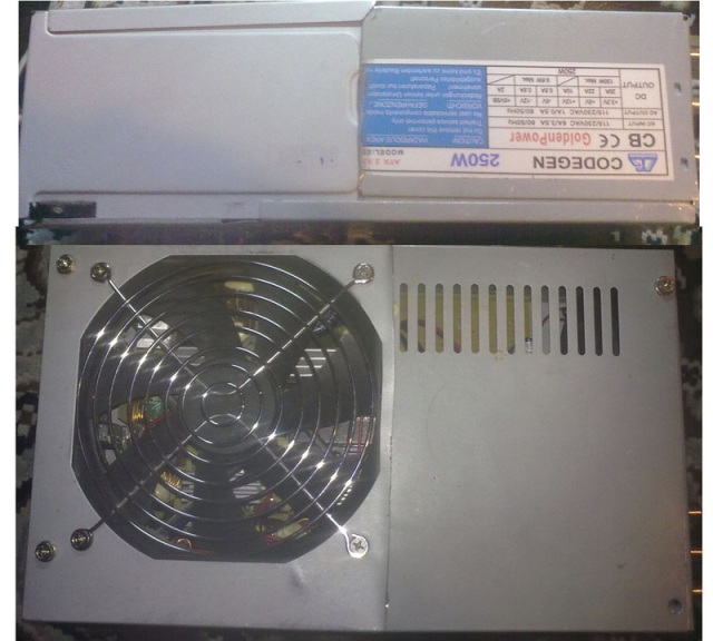
In the bins there were several old ATX power supplies, and a long and thorny path began to get the cherished 24 volts .
As you know, ATX has a line delivering -12 volts with a current of about 0.5 amps , so why not amplify it? But the first pancake, as you know, is in a lumpy: when trying to power a miracle, the soldering iron made a power supply unit “BZP3” and went into retirement.
')
The second attempt was made to make a voltage doubler. But the doubler to the input needs alternating current, which can be taken from the transformer. But, as it turned out, this path did not lead to success ...
The story continues under the cut (caution: a lot of pictures)
Of the weapons was only a cheap multimeter, which showed that the transformer about 10 volts AC. Well, you can go to battle! The doubler was assembled on the breadboard. Unfortunately, his picture was preserved only one, so to speak, in combat mode

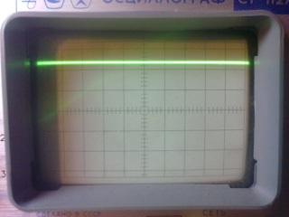
What a surprise when the multimeter showed all 50 volts at the output! It did not want to engage in the refutation of the physics postulates, so heavy artillery was acquired in the form of an oscilloscope. The picture on the findings of the transformer turned out next

This is with a 1:10 divider on the dipstick and the cost of division is 1 volt . It turns out the transformer and gives the cherished 24 volts , only a very terrible form (it is not surprising that the Chinese multimeter did not cope with the task).
New task - to convert doubler into rectifier. At the same time, it was decided to transfer the entire power section of the future soldering station to the power supply. The scheme turned out like this
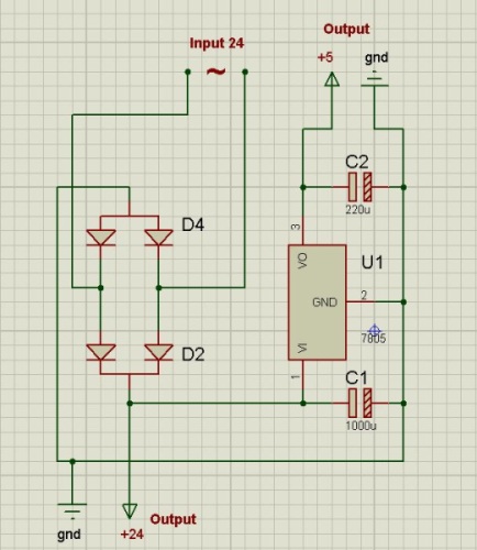
Explanation of the scheme:
Diodes D2 , D4 ( Schottky 30A 60V ) form a conventional diode bridge, the input of which comes in 24 volts of terrible shape, and the output - the same 24 , but constant (it is worth noting that the output current is almost flat!)
Stabilizer U1 ( 7805 ) reduces the voltage to 5 volts
Capacitors C1 ( 1000uF, 60V ) and C2 ( 220uF, 16V ) are electrolytes that act as filters. In theory, before leaving, it is still necessary to put ceramics that would catch high-frequency noise, but it will stand in the soldering station.
Appearance:
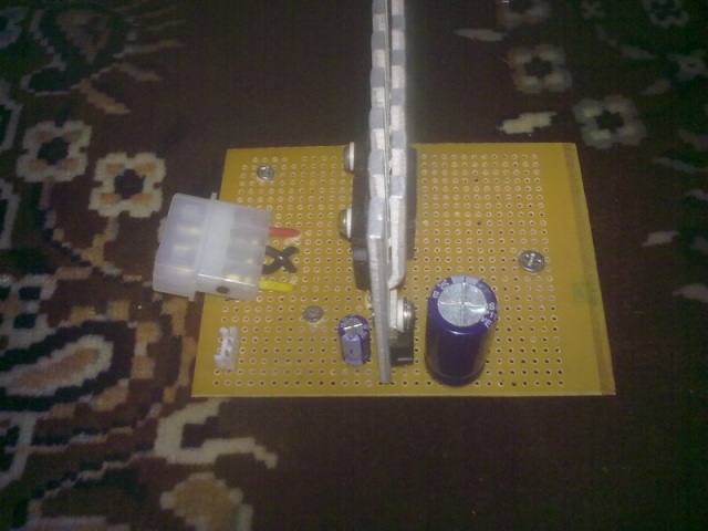
On this, the electronic part is finished, it remains to collect everything in the case.
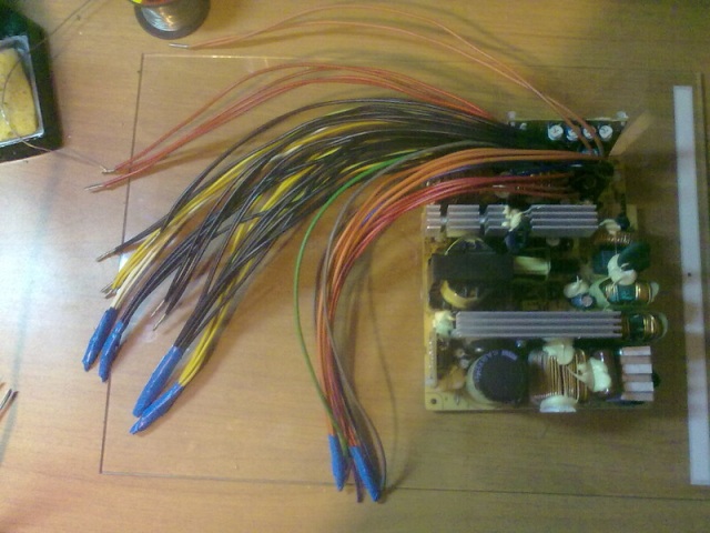
First we cut all the wires, they should fit comfortably in the housing. Wires are assembled in pairs to withstand a large load, the ends are wound and tinned.
After that, add the power supply start button. To start ATX, you need to close the PS_ON (green wire) to the ground (any of the black ones). I took 3 wires to the switch - PS_ON , GND and one of the +5 (red wire). The latter is needed to power the LED inside the button.

Oh, yes, the switch had to be slightly modified, because inside it was a halogen, designed for 220 volts . I had to pull out the giblets and replace them with a LED ( 5V ) and a resistor ( 511R ).
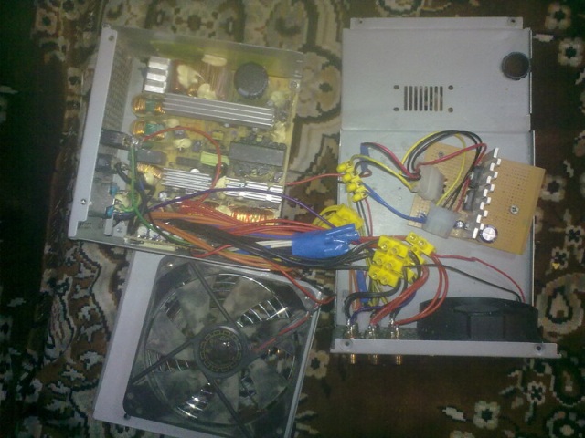
Brute force was applied to the body of a single power unit and it became flat (this would be the bottom of the structure).

At the current stage, a beta version of this type has been compiled and launched.

Cut off all the excess on the case with a cooler. So everything looks in a disassembled state:
On the case we place 9 RCA sockets and one Molex (output for soldering station)

Inside, it looks terrifying:

Outwardly, not much better, but not so scary:
It's time to check how our "extension" copes with its responsibilities.
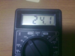
5 volts (division price - 2 volts , the oscilloscope is not slightly calibrated)

24 volts (division price of 1 volt + before the divider on the probe 1:10 )
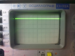
As you can see, copes well! A small stress test in the form of a two-hour torsion of a motor was also successfully passed. Finally, you can start creating a soldering station ...
Uh, it seems everything. Thanks to everyone who mastered to the end. I would be happy to criticize the design (version 2.0 will definitely be) and the text.
Ps. Thanks to TheHorse for inviting
I was fascinated by electronics until the moment when a cheap Chinese soldering iron became scarce. It was a volitional decision to assemble a soldering station with your own hands. But the trouble is, it turned out that in the city to get a 24-volt transformer is simply impossible. Thanks to this regrettable fact, the article was born.
In the bins there were several old ATX power supplies, and a long and thorny path began to get the cherished 24 volts .
As you know, ATX has a line delivering -12 volts with a current of about 0.5 amps , so why not amplify it? But the first pancake, as you know, is in a lumpy: when trying to power a miracle, the soldering iron made a power supply unit “BZP3” and went into retirement.
')
The second attempt was made to make a voltage doubler. But the doubler to the input needs alternating current, which can be taken from the transformer. But, as it turned out, this path did not lead to success ...
The story continues under the cut (caution: a lot of pictures)
Of the weapons was only a cheap multimeter, which showed that the transformer about 10 volts AC. Well, you can go to battle! The doubler was assembled on the breadboard. Unfortunately, his picture was preserved only one, so to speak, in combat mode
What a surprise when the multimeter showed all 50 volts at the output! It did not want to engage in the refutation of the physics postulates, so heavy artillery was acquired in the form of an oscilloscope. The picture on the findings of the transformer turned out next
This is with a 1:10 divider on the dipstick and the cost of division is 1 volt . It turns out the transformer and gives the cherished 24 volts , only a very terrible form (it is not surprising that the Chinese multimeter did not cope with the task).
New task - to convert doubler into rectifier. At the same time, it was decided to transfer the entire power section of the future soldering station to the power supply. The scheme turned out like this
Explanation of the scheme:
Diodes D2 , D4 ( Schottky 30A 60V ) form a conventional diode bridge, the input of which comes in 24 volts of terrible shape, and the output - the same 24 , but constant (it is worth noting that the output current is almost flat!)
Stabilizer U1 ( 7805 ) reduces the voltage to 5 volts
Capacitors C1 ( 1000uF, 60V ) and C2 ( 220uF, 16V ) are electrolytes that act as filters. In theory, before leaving, it is still necessary to put ceramics that would catch high-frequency noise, but it will stand in the soldering station.
Appearance:
On this, the electronic part is finished, it remains to collect everything in the case.
First we cut all the wires, they should fit comfortably in the housing. Wires are assembled in pairs to withstand a large load, the ends are wound and tinned.
After that, add the power supply start button. To start ATX, you need to close the PS_ON (green wire) to the ground (any of the black ones). I took 3 wires to the switch - PS_ON , GND and one of the +5 (red wire). The latter is needed to power the LED inside the button.
Oh, yes, the switch had to be slightly modified, because inside it was a halogen, designed for 220 volts . I had to pull out the giblets and replace them with a LED ( 5V ) and a resistor ( 511R ).
Brute force was applied to the body of a single power unit and it became flat (this would be the bottom of the structure).
At the current stage, a beta version of this type has been compiled and launched.
Cut off all the excess on the case with a cooler. So everything looks in a disassembled state:
On the case we place 9 RCA sockets and one Molex (output for soldering station)
Inside, it looks terrifying:
Outwardly, not much better, but not so scary:
It's time to check how our "extension" copes with its responsibilities.
5 volts (division price - 2 volts , the oscilloscope is not slightly calibrated)
24 volts (division price of 1 volt + before the divider on the probe 1:10 )
As you can see, copes well! A small stress test in the form of a two-hour torsion of a motor was also successfully passed. Finally, you can start creating a soldering station ...
Uh, it seems everything. Thanks to everyone who mastered to the end. I would be happy to criticize the design (version 2.0 will definitely be) and the text.
Ps. Thanks to TheHorse for inviting
Source: https://habr.com/ru/post/144398/
All Articles