Another copter: part two, frame collection
Continuing to build your aircraft make frame for the copter.
The article is part of a cycle:
1. Part one, description and selection of parts
2. Part two, frame assembly

picture again from google
')
Inside this part there will be a lot of pictures, watch the traffic.
First, a little tediousness. Generally speaking, this article is not unique. Going to a wonderful forum (and blogs ) on radio-controlled toys you can find thousands of similar first-flight stories. Waiting for details from China, I strongly advise you to read this forum. You can learn a lot of interesting solutions. Most likely your copter will be better than mine. I highly recommend this thread to collect frames. All that I will write here is drawn from these topics, and is simply an illustrated collection of tips that came in handy to me. You may need more.
So the first thing to do is choose a size. As far as I can tell from the result of reading several multi-page discussions, it makes no sense to make an “sweeping” copter, and even harmful for handling. The distance between the screws should be about three centimeters. Those. we take two screw radii (the same diameter) plus three centimeters (preferably four for fidelity) and we get a square formed by the axes of the motors. The diagonal of this square will give us the length of the beam (do not forget to add at least three centimeters on each side in order to fix the engines). Putting the screw radius from the shaft axis along the beam, we get the maximum size of the central area. Do it more, i.e. crawling under the screws is not necessary, you can do less, to win in weight. I went to my calculations in this way. We get about this drawing (the dimensions on it correspond to my copter):
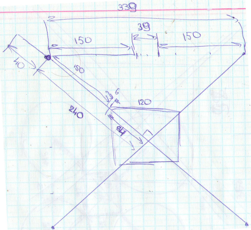
Here you can make sure that my handwriting is clumsy.
After that, I recommend to go to the layout: cut the rays and the center of the paper, make sure that everything turned out fine:
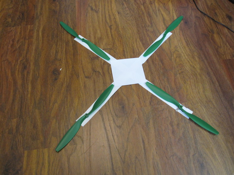
When I first figured out the size of the copter, before receiving the order, I incorrectly translated inches to centimeters. Avoid this error and measure all the details yourself, in patriotic centimeters :)
Well, if everything suits, then we go to cut the frame. I did it on the balcony, there I have a small improvised workbench.
We saw two beams and textolite:

Unfortunately, I missed the textolite layout and sawing stage, but there is nothing complicated about it. You will need two plates corresponding to your previously estimated sizes. For the legs, I just made four trapeziums. The legs can be done differently. For example, I saw a construction where corks were screwed to the rays, and small bottles of yogurt were screwed into them. They say that such a copter does not fall into the snow and is even able to swim, but it sails noticeably. Yes, I used foil textolite, because I did not find another nearby. All strongly advise him to pickle for relief, but I did not. Laziness. And not so much weight will win, I think. Better to drill holes in it. But if there is a possibility - take non-folded. It is better to cut in a sheath or gauze bandage; inhaling glass dust is very harmful.
UPD: KoteSoft added that it is convenient to cut textolite with metal scissors
Cooking compound:
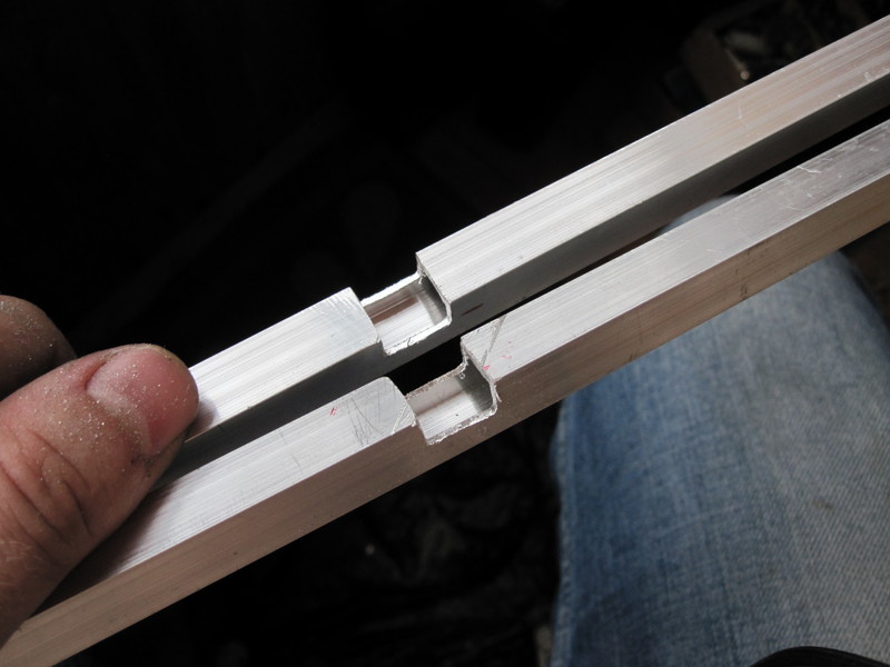
I will make a reservation that in all the instructions I saw in the frame, one beam was made whole, and the second of two pieces of aluminum. I decided to go against the system and cut both to the middle. My logic is simple - in any case, strength is equal to the strength of the weakest link, and if one beam is sawed entirely and rests only on the screws that are bolted to the PCB, then what is the use of the second one?
We connect:

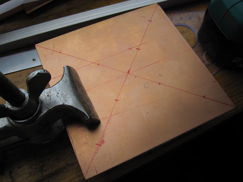
Accuracy is important in this place, the angle must be taken exactly 90. I used a gon for this, and I slightly grabbed the rays with hot glue so that they would not move during the further assembly.
We join the plates together and drill in places where we will fix the rays:
Then I made a mistake, chose places by the eye, and the screw head prevented me from making a battery mount, literally a few millimeters to the side, and I wouldn’t have to fence the lining, but more on that later. Just try to estimate in advance the placement of the remaining components.
We put the plate on the copter, transfer holes, drill and check.
Here I made the second big mistake. If you drill holes tightly (3mm for screws from the previous article), then the slightest deviation will lead to the fact that the screws in the holes do not fall. If you make holes not on a CNC machine, they will still not be completely symmetrical. Therefore, on all the parts to be combined, place a mark on one of the corners. This will be the "top and front". Otherwise, as you will for a long time I will twist the plate with different sides to get into these damn holes. :)
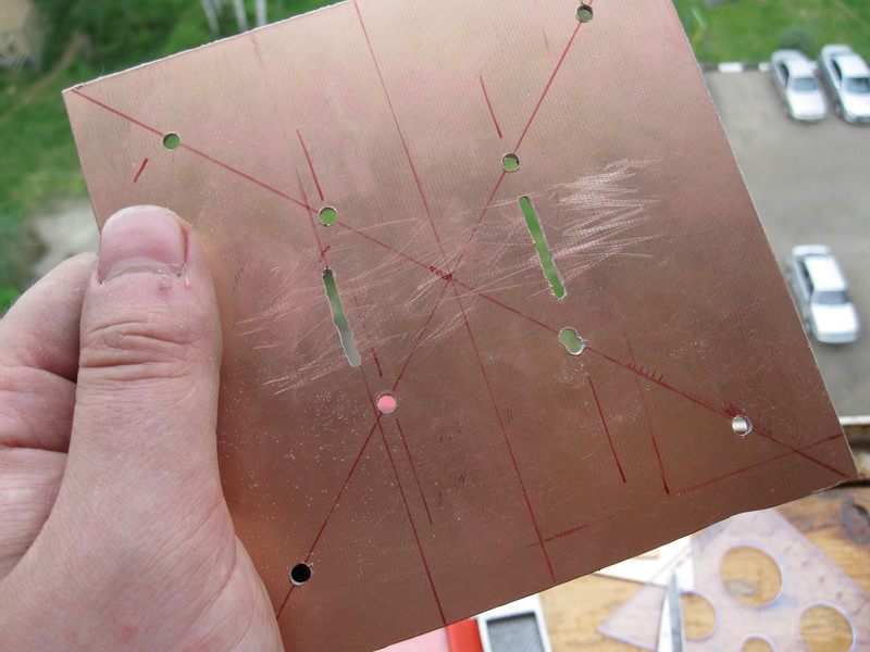
We take the bottom of the cans from under the CD and drilled around the holes remove the core from it:
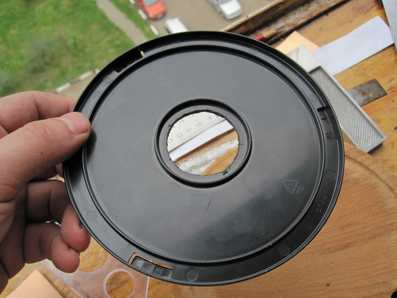
Looking ahead to say that one core is not enough, and you will need more holes opposite the rays. They will be seen at the end of the article.
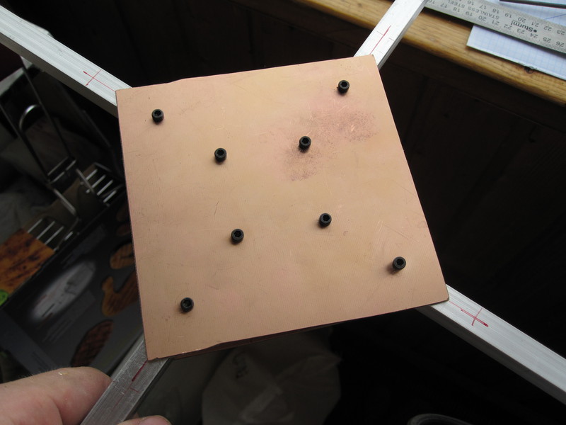
We fasten the base on the screws, placing a rubber tube or any other vibration absorber as a layer.
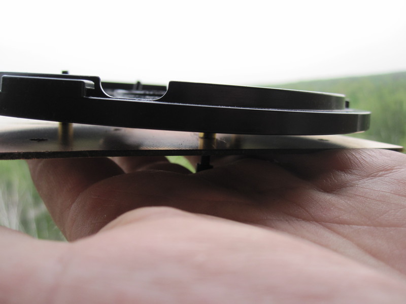
They say gum from CD drives fit very well, but I didn’t have them on hand. We do not fasten the base, but just make sure that everything fits.
Battery mount
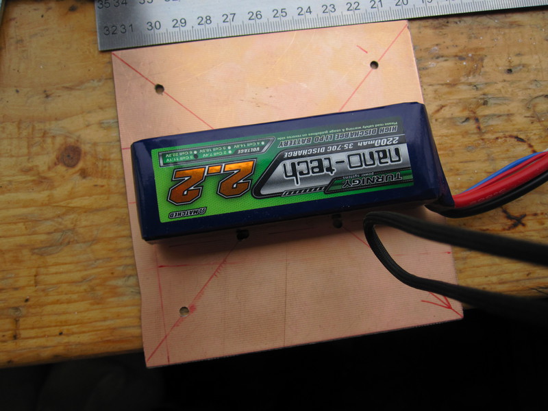
In this picture you can see that the heads of the screws will make it difficult to press the battery close to the board, you will have to put in pieces of wine cork (light and not very smooth), so that the screws do not interfere.
Drill a hole for mounting:
Now I have fastened Velcro there, but in the future I will replace it with a tightening tape, with a lock similar to those used in the straps for backpacks. I do not know how they are called, but judging by the video, it’s very effective. Velcroe hold the battery unreliably.
Under the top board, we enclose something for vibration isolation. I used thin trim from the control board packaging.

If you look between the rays you can see hot melt glue.
Mount engines is simple. From the center we measure the points where the axes should be (here it is better to measure it more precisely and more conveniently before connecting the rays). From the edge it is better not to measure, suddenly you made the connection not exactly in the center? We attach the crosses of the motors, mark up the holes and fasten the motors:
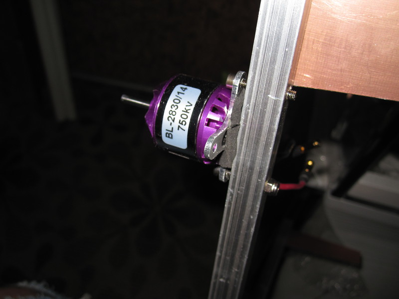
Under the motors, I also put a kind of foam. This solution in my opinion is not very good, the motors must be attached rigidly. Now there it is not. With motors, be careful. On some motors the wires may come off the bend. It seems to me not very easy to disassemble (and most importantly assemble back) the motor. Yes, and why if you can do without it. If the wires on your motors are very flimsy, fix them at the base with hot glue.
I did not fix the stage of screwing the legs, but there is nothing difficult there. I made the legs behind the motors in order not to first of all pierce the beam at the motor-center site, and so as to “curve” the landing, not to fasten the ground with a screw. Even for this, you can lengthen the beams with strips or a plastic cable box, you will see this in the next article.
We twist everything together - the frame is ready:
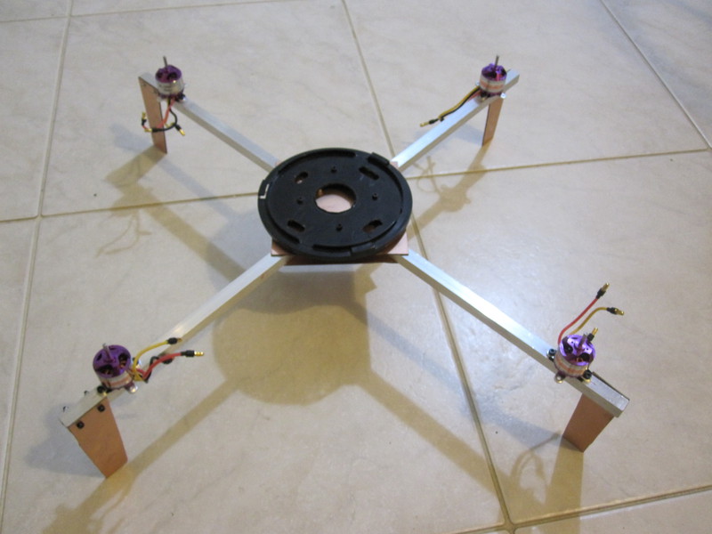
Note the four additional holes opposite the beam at the base of the can for blanks. The wires will go through them, the center will completely close the board.
At this point, the Russian national hockey team went on the ice to win the semifinal, and I went to get sick. Assembling and configuring electronics took me almost the whole next day and will be the topic of the next two articles.
Those who read read the promised video of the first flight . It really resembles a nightmare , but something youtube with my fotikom is not very mated.
About errors, please report to the PM. I will correct, I will add UPD, at will I will specify your username.
The article is part of a cycle:
1. Part one, description and selection of parts
2. Part two, frame assembly
picture again from google
')
Inside this part there will be a lot of pictures, watch the traffic.
First, a little tediousness. Generally speaking, this article is not unique. Going to a wonderful forum (and blogs ) on radio-controlled toys you can find thousands of similar first-flight stories. Waiting for details from China, I strongly advise you to read this forum. You can learn a lot of interesting solutions. Most likely your copter will be better than mine. I highly recommend this thread to collect frames. All that I will write here is drawn from these topics, and is simply an illustrated collection of tips that came in handy to me. You may need more.
So the first thing to do is choose a size. As far as I can tell from the result of reading several multi-page discussions, it makes no sense to make an “sweeping” copter, and even harmful for handling. The distance between the screws should be about three centimeters. Those. we take two screw radii (the same diameter) plus three centimeters (preferably four for fidelity) and we get a square formed by the axes of the motors. The diagonal of this square will give us the length of the beam (do not forget to add at least three centimeters on each side in order to fix the engines). Putting the screw radius from the shaft axis along the beam, we get the maximum size of the central area. Do it more, i.e. crawling under the screws is not necessary, you can do less, to win in weight. I went to my calculations in this way. We get about this drawing (the dimensions on it correspond to my copter):
Here you can make sure that my handwriting is clumsy.
After that, I recommend to go to the layout: cut the rays and the center of the paper, make sure that everything turned out fine:
When I first figured out the size of the copter, before receiving the order, I incorrectly translated inches to centimeters. Avoid this error and measure all the details yourself, in patriotic centimeters :)
Well, if everything suits, then we go to cut the frame. I did it on the balcony, there I have a small improvised workbench.
We saw two beams and textolite:
Unfortunately, I missed the textolite layout and sawing stage, but there is nothing complicated about it. You will need two plates corresponding to your previously estimated sizes. For the legs, I just made four trapeziums. The legs can be done differently. For example, I saw a construction where corks were screwed to the rays, and small bottles of yogurt were screwed into them. They say that such a copter does not fall into the snow and is even able to swim, but it sails noticeably. Yes, I used foil textolite, because I did not find another nearby. All strongly advise him to pickle for relief, but I did not. Laziness. And not so much weight will win, I think. Better to drill holes in it. But if there is a possibility - take non-folded. It is better to cut in a sheath or gauze bandage; inhaling glass dust is very harmful.
UPD: KoteSoft added that it is convenient to cut textolite with metal scissors
Cooking compound:
I will make a reservation that in all the instructions I saw in the frame, one beam was made whole, and the second of two pieces of aluminum. I decided to go against the system and cut both to the middle. My logic is simple - in any case, strength is equal to the strength of the weakest link, and if one beam is sawed entirely and rests only on the screws that are bolted to the PCB, then what is the use of the second one?
We connect:
Accuracy is important in this place, the angle must be taken exactly 90. I used a gon for this, and I slightly grabbed the rays with hot glue so that they would not move during the further assembly.
We join the plates together and drill in places where we will fix the rays:
Then I made a mistake, chose places by the eye, and the screw head prevented me from making a battery mount, literally a few millimeters to the side, and I wouldn’t have to fence the lining, but more on that later. Just try to estimate in advance the placement of the remaining components.
We put the plate on the copter, transfer holes, drill and check.
Here I made the second big mistake. If you drill holes tightly (3mm for screws from the previous article), then the slightest deviation will lead to the fact that the screws in the holes do not fall. If you make holes not on a CNC machine, they will still not be completely symmetrical. Therefore, on all the parts to be combined, place a mark on one of the corners. This will be the "top and front". Otherwise, as you will for a long time I will twist the plate with different sides to get into these damn holes. :)
We take the bottom of the cans from under the CD and drilled around the holes remove the core from it:
Looking ahead to say that one core is not enough, and you will need more holes opposite the rays. They will be seen at the end of the article.
We fasten the base on the screws, placing a rubber tube or any other vibration absorber as a layer.
They say gum from CD drives fit very well, but I didn’t have them on hand. We do not fasten the base, but just make sure that everything fits.
Battery mount
In this picture you can see that the heads of the screws will make it difficult to press the battery close to the board, you will have to put in pieces of wine cork (light and not very smooth), so that the screws do not interfere.
Drill a hole for mounting:
Now I have fastened Velcro there, but in the future I will replace it with a tightening tape, with a lock similar to those used in the straps for backpacks. I do not know how they are called, but judging by the video, it’s very effective. Velcroe hold the battery unreliably.
Under the top board, we enclose something for vibration isolation. I used thin trim from the control board packaging.
If you look between the rays you can see hot melt glue.
Mount engines is simple. From the center we measure the points where the axes should be (here it is better to measure it more precisely and more conveniently before connecting the rays). From the edge it is better not to measure, suddenly you made the connection not exactly in the center? We attach the crosses of the motors, mark up the holes and fasten the motors:
Under the motors, I also put a kind of foam. This solution in my opinion is not very good, the motors must be attached rigidly. Now there it is not. With motors, be careful. On some motors the wires may come off the bend. It seems to me not very easy to disassemble (and most importantly assemble back) the motor. Yes, and why if you can do without it. If the wires on your motors are very flimsy, fix them at the base with hot glue.
I did not fix the stage of screwing the legs, but there is nothing difficult there. I made the legs behind the motors in order not to first of all pierce the beam at the motor-center site, and so as to “curve” the landing, not to fasten the ground with a screw. Even for this, you can lengthen the beams with strips or a plastic cable box, you will see this in the next article.
We twist everything together - the frame is ready:
Note the four additional holes opposite the beam at the base of the can for blanks. The wires will go through them, the center will completely close the board.
At this point, the Russian national hockey team went on the ice to win the semifinal, and I went to get sick. Assembling and configuring electronics took me almost the whole next day and will be the topic of the next two articles.
Those who read read the promised video of the first flight . It really resembles a nightmare , but something youtube with my fotikom is not very mated.
About errors, please report to the PM. I will correct, I will add UPD, at will I will specify your username.
Source: https://habr.com/ru/post/144248/
All Articles