Optical Switch with Sound Effect on Arduino
Good day!
In this post I want to share with habr a community about the principle of work made by me
proximity switch. The switch is planned to be used in the smart home system.
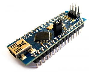
The basis of the switch is a recently improved Arduino controller clone sold by me, sold under the name Carduino Nano V.7
The switch works as follows:
Arduino from the output of the D5 constantly produces a PWM signal with a frequency of 976 Hz and a duty cycle of 50%. To exit
D5 through the current-limiting resistor connected LED emitting a light signal in the infrared. A phototransistor connected to the input of the Arduino D2 detects
IR reflected by hand. Arduino receives an IR signal, checks it for accuracy and if the signal from 20 consecutive pulses corresponds to a frequency of 976 Hz, then the controller turns on the blue LED (L) at the output of the D13 Arduino and starts to play a sound effect through the SPK output of the controller. All the same thing happens when turning off the LED (L).
')
Reproduction:
When playing sound effects, a WAV sound file format without compression is used, with a frequency of 16000 Hz and a depth of 8 bits.
To improve the quality of sound reproduction, linear interpolation is used. For this, the sampling takes place at a frequency of 96000 Hz and 4 intermediate samples calculated by the method of linear interpolation are inserted between the original samples. In this way, the quantization noise is reduced, the quality is improved, and additional filters are not required to play sounds.
The scheme is simple to build it, I used
1-Carduino Nano V.7
2-IR LED from the old remote control from the TV, the LED must be heat shrinked to avoid side radiation
3-Phototransistor LTR-3208E
4-Dynamic head from a children's toy
5-resistors 10k and 68th

How the scheme I collected on the breadboard works, you can look at the video.
Code for Arduino Nano:
Download the source in one file
In the following article:
The Arduino Nano will be replaced by an Atmega328 controller, the entire circuit with the power supply will be assembled on a separate board and installed in the corridor switch.
In this post I want to share with habr a community about the principle of work made by me
proximity switch. The switch is planned to be used in the smart home system.
The basis of the switch is a recently improved Arduino controller clone sold by me, sold under the name Carduino Nano V.7
The switch works as follows:
Arduino from the output of the D5 constantly produces a PWM signal with a frequency of 976 Hz and a duty cycle of 50%. To exit
D5 through the current-limiting resistor connected LED emitting a light signal in the infrared. A phototransistor connected to the input of the Arduino D2 detects
IR reflected by hand. Arduino receives an IR signal, checks it for accuracy and if the signal from 20 consecutive pulses corresponds to a frequency of 976 Hz, then the controller turns on the blue LED (L) at the output of the D13 Arduino and starts to play a sound effect through the SPK output of the controller. All the same thing happens when turning off the LED (L).
')
Reproduction:
When playing sound effects, a WAV sound file format without compression is used, with a frequency of 16000 Hz and a depth of 8 bits.
To improve the quality of sound reproduction, linear interpolation is used. For this, the sampling takes place at a frequency of 96000 Hz and 4 intermediate samples calculated by the method of linear interpolation are inserted between the original samples. In this way, the quantization noise is reduced, the quality is improved, and additional filters are not required to play sounds.
The scheme is simple to build it, I used
1-Carduino Nano V.7
2-IR LED from the old remote control from the TV, the LED must be heat shrinked to avoid side radiation
3-Phototransistor LTR-3208E
4-Dynamic head from a children's toy
5-resistors 10k and 68th
How the scheme I collected on the breadboard works, you can look at the video.
Code for Arduino Nano:
#include <TimerOne.h> #include <avr/delay.h> #include <avr/pgmspace.h> #include "fife.h" #include "hi.h" //////// //////////////////////////////////// #define speakerPin 11 volatile uint16_t sample=0; volatile uint8_t lastSample, FirstSample; volatile byte new_data,future_data,old_data; volatile byte stat=0; unsigned char *wave; unsigned int length; //////// //////////////////////////////////// uint8_t state = 0; volatile uint16_t timerCount, lengthImpuls; volatile uint16_t Counter=0; //////////// /////////////////////////////// void setup() { pinMode(speakerPin, OUTPUT); // digitalWrite(speakerPin, LOW); // pinMode(2, INPUT); // , // digitalWrite(2, HIGH); // pinMode(13, OUTPUT); // pinMode(5, OUTPUT); // TCCR0B = TCCR0B & 0b11111000 | 3; // 976 analogWrite(5,128 ); // attachInterrupt(0, Ir_sens, RISING); // Timer1.initialize(10); // Timer1.attachInterrupt(callback); // } //////////// /////////////////////////////// void callback() { timerCount++; } //////////// /////////////////////////////// void Ir_sens() { lengthImpuls = timerCount; timerCount=0; Counter++; } /////////////////////// OCR2/////////////////// ISR(TIMER2_COMPA_vect) { switch (stat) { case 0:{ old_data = pgm_read_byte(&wave[sample]); OCR2A = old_data; stat=1; ++sample; if (sample == length) stat=4; future_data = pgm_read_byte(&wave[sample]); new_data = (old_data+future_data)/2; } break; case 1: {OCR2A=(old_data+new_data)/2; stat=2; } break; case 2: {OCR2A = new_data; stat=3; } break; case 3: {OCR2A=(new_data+future_data)/2; stat=0; } break; case 4: if(lastSample==0) stat=5; else {--lastSample; OCR2A=lastSample;} break; case 5: stopPlayback(); break; } } //////////// /////////////////////////////// void loop() { if(lengthImpuls>105 || lengthImpuls<99) Counter=0; if(lengthImpuls>99 && lengthImpuls<105 && Counter>20) { state=~state; digitalWrite(13, state); if(state>0) play_wave((unsigned char *)hi, hi_length); if(state==0) play_wave((unsigned char *)fife, fife_length); _delay_ms(200); while(Counter>10) { if(lengthImpuls>105 || lengthImpuls<99) Counter=0; } lengthImpuls=0; } } //////////// /////////////////////////////// void play_wave(unsigned char *wave_data, unsigned int wave_length) { wave=wave_data; length=wave_length; startPlayback(); } void startPlayback() { sample=0; stat=0; ASSR |=(1<<AS2); TCCR2A |= ((1<<COM2B1)|(0<<COM2B0)|(1<<COM2A1)|(0<<COM2A0)|(1<<WGM21)|(0<<WGM20)); TCCR2B = ((0 << CS22) | (0 << CS21) | (1 << CS20) | (0<<WGM22) | (1<<FOC2A) | (1<<FOC2B)); lastSample = pgm_read_byte(&wave[length-1]); TCNT2 = 0; TIMSK2|=(1<<OCIE2A); sei(); for (int i=0; i <50; i++) { new_data=i; stat=2; sample = 0; _delay_us(1); } stat=0; } //////////// /////////////////////////////// void stopPlayback() { TIMSK2&=(0<<OCIE2A); TCCR2B &=(0<<CS10); } Download the source in one file
In the following article:
The Arduino Nano will be replaced by an Atmega328 controller, the entire circuit with the power supply will be assembled on a separate board and installed in the corridor switch.
Source: https://habr.com/ru/post/144180/
All Articles