Networks for the smallest. Part Four STP
I think that I never see
A graph more lovely than a tree.
A tree whose crucial propertyeu
Is loop-free connectivity.
A tree that must be sure to span
So packets can reach every LAN.
First, the root must be selected.
By ID, it is elected.
Least-cost paths from root are traced.
In the tree, these paths are placed.
A mesh is made by folks like me,
Then bridges find a spanning tree.
- Radia Joy Perlman
6. Networks for the smallest. Part six. Dynamic routing
5. Networks for the smallest: Part Five. NAT and ACL
4. Networks for the smallest: Part Four. STP
3. Networks for the smallest: Part Three. Static routing
2. Networks for the smallest. Part two. Switching
1. Networks for the smallest. Part one. Connection to the equipment cisco
0. Networks for the smallest. Part zero. Planning
In the last issue, we stopped at static routing. Now we need to take a step aside and discuss the issue of the stability of our network.
Once, when you - the only network administrator of the company “Lift Ei Ap” - asked for a half day before, the connection with the servers suddenly fell, and the directors did not receive several important letters. After a short but tangible thrashing, you go to figure out what's the matter, but it turned out that, due to some carelessness, the only cable that led to the switch in the server cable fell out of the connector. A small problem that you could fix in two minutes, and even avoid it altogether, significantly affected your income this month and growth opportunities.
')
So today we are discussing:
The equipment operating at the second level of the OSI model (switch) should perform 3 functions: storing addresses, forwarding (switching) packets, protection from loops in the network. Let us consider the points of each function.
Memorizing addresses and packet forwarding : As we said earlier , each switch has a MAC address and port mapping table (aka CAM-table - Content Addressable Memory Table). When a device connected to a switch sends a frame to the network, the switch looks at the sender's MAC address and the port from which the frame was received, and adds this information to its table. Next, it must transfer the frame to the recipient whose address is specified in the frame. In theory, the information about the port where the frame is to be sent, it takes from the same CAM table. But suppose that the switch has just been turned on (the table is empty), and it has no idea which of its ports the receiver is connected to. In this case, it sends the received frame to all its ports, in addition, from where it was received. All end devices, having received this frame, look at the recipient's MAC address, and, if it is not addressed to them, discard it. The receiving device responds to the sender, and in the field of the sender puts its address, and now the switch already knows that such and such address is on such and such port (makes a record in the table), and next time it will forward the frames addressed to this device , only to this port. To view the contents of the CAM table, use the show mac address-table command. Once in the table, the information does not remain there for life, the content is constantly updated and if a certain mac-address is not accessed for 300 seconds (by default), the entry about it is deleted.
Everything should be clear here. But why protection from loops ? And what is it all about?
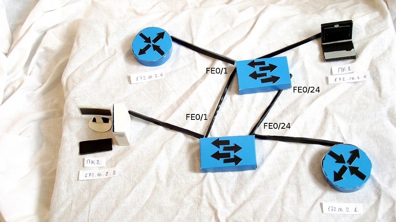
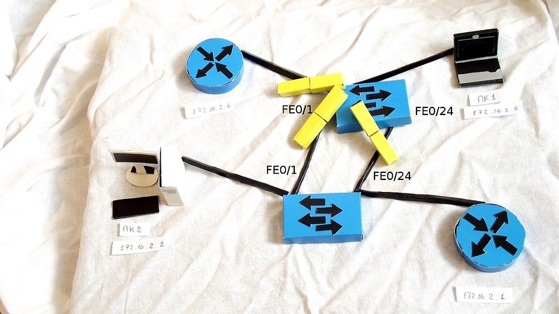
Often, to ensure the stability of the network in case of problems with communication between the switches (port failure, wire break), use redundant links (additional connections). The idea is simple - if between links for some reason one link does not work, we use a spare one. It seems everything is correct, but imagine a situation like this: two switches are connected by two wires (let it be that they have fa0 / 1 and fa0 / 24 connected).
One of their wards, workstations (for example, PC1), suddenly wanted to send a broadcast frame (for example, an ARP request). Once broadcast, a helmet to all ports, in addition, from which it was received.
The second switch receives a frame in two ports, sees that it is broadcast, and also sends to all ports, but already, it turns out, and back to those from which it received (a frame from fa0 / 24 sends to fa0 / 1, and vice versa).

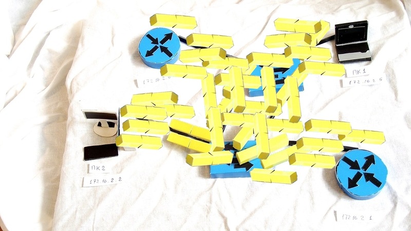
The first switch does exactly the same, and in the end we get a broadcast storm (broadcast storm), which tightly blocks the network, because the switches are now only engaged in sending each other the same frame.
How can you avoid this? After all, we, on the one hand, do not want storms on the network, but on the other, we want to increase its resiliency by using redundant connections? This is where STP (Spanning Tree Protocol) comes to our rescue.
The main objective of STP is to prevent loops from appearing on the second level. How to do it? Yes, just chop off all the redundant links until we need them. Here, many questions immediately arise: which link of two (or three or four) to chop off? How to determine that the main link fell, and it's time to include a spare? How to understand that the network has formed a loop? To answer these questions, you need to figure out how STP works.
STP uses the STA (Spanning Tree Algorithm) algorithm, the result of which is a tree-like graph (connected and without simple cycles )
To exchange information between themselves, the switches use special packages, the so-called BPDU (Bridge Protocol Data Units). BPDUs are of two types: configurational (Configuration BPDU) and panic “AAA, topology changed!” TCN (Topology Change Notification BPDU). The first ones are regularly sent by the root switch (and relayed by the others) and are used to build the topology, the second ones, as the name implies, are sent when the network topology changes (in other words, connecting / disconnecting the switch). Configuration BPDUs contain several fields, let's dwell on the most important ones:
What is all this and why it is needed, I will explain a little lower. Since the devices do not know and do not want to know their neighbors, they do not establish any relationship (adjacency / neighborhood) with each other. They send BPDUs from all working ports to the multicast ethernet address 01-80-c2-00-00-00 (every 2 seconds by default), which all switches with STP on will listen.
So, how does the topology form without loops?
First, the so-called root bridge is selected. This is the device that the STP considers the point of reference, the center of the network the whole STP tree converges to it. The choice is based on the concept of a Bridge ID. Bridge ID is a number of 8 bytes in length, which consists of Bridge Priority (priority, from 0 to 65535, default 32768 + vlan number or MSTP instance, depending on the implementation of the protocol), and the MAC address of the device. At the beginning of the election, each switch considers itself to be the root, and it declares everything else with the help of BPDU, in which it presents its ID as the root switch ID. At the same time, if he gets a BPDU with a smaller Bridge ID, he stops bragging about his own and dutifully begins to announce the resulting Bridge ID as the root. As a result, the root switch is the one whose Bridge ID is the least.
After the switches have found their way out and have chosen the root bridge, each of the other switches should find one and only one port that will lead to the root switch. This port is called the root port . To understand which port is best to use, each non-root switch determines the cost of the route from each of its ports to the root switch. This cost is determined by the sum of the cost of all links that need to go through the frame to get to the root switch. In turn, the cost of a link is determined simply by its speed (the higher the speed, the lower the cost). The process of determining the cost of the route is associated with the BPDU “Root Path Cost” field and happens as follows:
If the same costs occur (as in our example with two switches and two wires between them, each path will have a cost of 19) - the smaller port is selected as the root.
Next, select Designated ports. From each particular network segment, there should be only one way towards the root switch, otherwise it is a loop. In this case, we mean the physical segment, in modern networks without hubs, roughly speaking, this is just a wire. The designated port is the one that has the best value in this segment. At the root switch, all ports are designated.
And now, after the root and designated ports are selected, the remaining ones are blocked, thus breaking the loop.
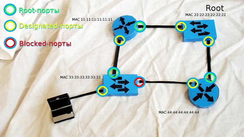
* In the picture, routers act as switches. In real life this can be done with the help of an additional switchboard.
Earlier we mentioned the port blocking status, now let's talk about what this means, and about other possible port states in STP. So, in the usual (802.1D) STP there are 5 different states:
The order of enumeration of states is not accidental: when turned on (as well as when a new wire is plugged in), all ports on the device with STP pass through the above states in that order (except for disabled ports). A natural question arises: why such difficulties? And just STP cautious. After all, at the other end of the wire, which has just been plugged into the port, there can be a switch, and this is a potential loop. That's why the port first 15 seconds (by default) is in the listening state - it watches BPDUs that fall into it, finds out its position in the network - no matter how it happens, then it goes to training for 15 seconds - trying to figure out which mac- the addresses are “in progress” on the link, and then, making sure that he does not break anything, he begins his work. In total, we have as many as 30 seconds of idle time before the connected device can exchange information with its neighbors. Modern computers are loaded in less than 30 seconds. Now the computer has booted up, is already breaking into the network, hysteria on the subject “DHCP server, you bastard, will you issue an IP address, or not?” Naturally, after such Exercises, no one will listen to him on the network, because “not local” with his 169.254.xx It is clear that all this is not the case, but how to avoid it?
For such cases, a special port mode is used - portfast. When a device is connected to such a port, it, bypassing the intermediate stages, immediately goes to the forwarding state. Of course, portfast should be enabled only on interfaces leading to end devices (workstations, servers, telephones, etc.), but not to other switches.
STP is quite an old protocol, it was created to work in one LAN segment. What to do if we want to implement it in our network, which has several VLANs?
The 802.1Q standard we mentioned in the article about switching determines how the vlans are transmitted inside the trunk. In addition, it defines one STP process for all vlans. BPDUs on trunks are transmitted untagged (to the native VLAN). This variant of STP is known as CST (Common Spanning Tree). Having only one process for all vlans greatly simplifies the setup work and offloads the switch processor, but, on the other hand, CST has drawbacks: redundant links between switches are blocked in all vlans, which is not always acceptable and does not allow them to be used for load balancing.
Cisco has its own look at STP, and its proprietary protocol implementation - PVST (Per-VLAN Spanning Tree) - which is designed to work on a network with several VLANs. In PVST, for each vlan, there is its own STP process, which allows independent and flexible adjustment to the needs of each vlan, but most importantly, it allows the use of load balancing due to the fact that a specific physical link can be blocked in one vlan, but work in another. The disadvantage of this implementation is, of course, proprietary: for the functioning of PVST, a proprietary ISL trunk between switches is required.
There is also a second version of this implementation - PVST + , which allows you to establish a connection between switches with CST and PVST, and works with both ISL-trunk and 802.1q. PVST + is the default protocol on Cisco switches.
Everything we talked about earlier in this article belongs to the first implementation of the STP protocol, which was developed in 1985 by Radia Permman (her poem was used as an epigraph). In 1990, this implementation was included in the IEEE 802.1D standard. Then the time flowed more slowly, and the STP topology reorganization, which takes 30-50 seconds (!!!), suited everyone. But times are changing, and ten years later, in 2001, IEEE introduces a new RSTP standard (aka 802.1w, aka Rapid Spanning Tree Protocol, aka Fast STP). To structure the previous material and see the differences between normal STP (802.1d) and RSTP (802.1w), let's put together a table with the main facts:
As we can see, in RSTP, such port roles as the root and assigned ones remained, and the role of the blocked one was divided into two new roles: Alternate and Backup. Alternate is the backup root port, and backup is the designated backup port. It is in this concept of backup ports that one of the reasons for fast switching in case of failure lies. This changes the behavior of the system as a whole: instead of reactive (which starts looking for a solution to the problem only after it has happened), the system becomes proactive, calculating the “escape routes” before the problem occurs. The point is simple: in order for the main to fail to switch to the backup link, RSTP does not need to re-calculate the topology, it will simply switch to the spare, previously calculated.
Previously, in order to make sure that the port could participate in data transmission, timers were required, i.e. the switch was passively waiting for the allotted time while listening to the BPDU. The key feature of RSTP was the introduction of the concept of port types based on link mode — full duplex or half duplex (port types p2p or shared, respectively), as well as the concept of border port (type edge p2p) for end devices. The border ports are assigned, as before, by the spanning-tree portfast command, and with them everything is clear; when you turn on the wires, we immediately go to the forwarding state and work. Shared ports operate according to the old scheme with passing through BLK - LIS - LRN - FWD states. But on p2p-ports RSTP uses the process of proposal and agreement (proposal and agreement). Without going into details, it can be described as follows: the switch rightly believes that if the link works in the full duplex mode, and it is not marked as borderline, it means that there are only two devices on it, he and the other switch. Instead of waiting for incoming BPDUs, he tries to contact the switch on the other end of the wire with the help of a special proposal BPDU, which, of course, has information about the cost of the route to the root switch. The second switch compares the received information with its current one, and makes a decision about what the first switch notifies by agreement BPDU. Since this whole process is no longer tied to timers, it happens very quickly — they just plugged in a new switch, and it almost immediately fit into the general topology and got to work (you can yourself evaluate the switching speed in comparison with regular STP on video). In the Cisco world, RSTP is called PVRST (Per-Vlan Rapid Spanning Tree).
Slightly above, we mentioned PVST, in which each Vlan has its own STP process. Vlans are a fairly convenient tool for many purposes, and therefore, they can be quite a lot even in a medium-sized organization. And in the case of PVST, each will have its own topology, processor time and switch memory. Do we need to calculate STP for all 500 vlans, when the only place where we need it is a backup link between two switches? Here MSTP helps us out. In it, each vlan is not required to have its own STP process, they can be combined. Here we have, for example, 500 vlans, and we want to balance the load so that half of them work on one link (the second one is blocked and kept in reserve), and the second one is different. This can be done with the help of a regular STP, by assigning one root switch in the range of Vlans 1-250, and the other in the range of 250-500. But the processes will work for each of the five hundred vlans separately (although they will act in exactly the same way for each half). It is logical that there will be enough two processes. MSTP allows you to create as many STP processes as we have logical topologies (in this example, 2), and distribute Vlans over them. We think that there is not much point in delving into the theory and practice of MSTP within the framework of this article (for theories there-th), those interested can follow the link.
But whatever STP option we use, we still somehow have a broken link. Is it possible to use parallel links to the full and avoid loops? Yes, we answer with ciscus, starting the story about EtherChannel.
Otherwise it is called link aggregation, link bundling, NIC teaming, port trunkinkg
Channel aggregation (aggregation) technologies perform 2 functions: on the one hand, it is the aggregation of the capacity of several physical links, and on the other, ensuring the fault tolerance of the connection (in the event of a link falling, the load is transferred to the remaining ones). Linking can be performed either manually (static aggregation) or using special protocols: LACP (Link Aggregation Control Protocol) and PAgP (Port Aggregation Protocol). LACP, defined by the IEEE 802.3ad standard, is an open standard, that is, it does not depend on the hardware vendor. Accordingly, PAgP is a proprietary tsiskovskaya development.
Up to eight ports can be combined into one such channel. The load balancing algorithm is based on parameters such as the IP / MAC addresses of the recipients and senders and the ports. Therefore, in case of a question: “Hey, why is it so poorly balanced?” First of all look at the balancing algorithm.
The topic of channel aggregation deserves a separate article, and even books, so we will not go deep for those interested in reference.
Now we will tell briefly how to ensure network security at the second OSI level. In this part of the article, the theory and practical configuration are combined. Alas, Packet Tracer is not able to do anything of the commands mentioned in this section, therefore everything is without illustrations and checks.
To begin with, mention should be made of the switchport port-security interface configuration command, which includes security on a specific switch port.Then, using switchport port-security maximum 1, we can limit the number of mac-addresses associated with this port (that is, in our example, only one mac-address can work on this port). Now we specify which address is allowed: you can manually set the switchport port-security mac-address address , or use the magic switchport port-security mac-address sticky command that secures the port address that is currently running on the port. Next, we set the behavior in case of violation of the switchport rule port-security violation {shutdown | restrict | protect}: the port is either disabled, and then it needs to be lifted manually (shutdown), or it discards packets from an unregistered poppy and writes about it to the console (restrict), or simply discards the packets (protect).
— — , , : . — CAM-. , , , MAC- . . , , - , 16000 . . : , , , , MAC- ( ), . , .
Another possible attack is aimed at a DHCP server. As we know, DHCP provides client devices with all the necessary information to work on the network: ip-address, subnet mask, default address, DNS server, and so on. The attacker can raise his own DHCP, which, in response to a request from the client device, will send as the default gateway (as well as, for example, the DNS server) the address of the attacker-controlled machine. Accordingly, all traffic sent outside the subnet by deceived devices will be available for the attacker to study - a typical man-in-the-middle attack. Either this option: a vile scammer generates a bunch of DHCP requests with fake MAC addresses and a DHCP server for each such request issues an IP address until the pool is exhausted.
In order to protect against this type of attack, a feature called DHCP snooping is used. The idea is quite simple: tell the switch on which port the real DHCP server is connected, and only allow DHCP responses from this port, prohibiting others. We enable globally with the ip dhcp snooping command , then we say in which vlans ip dhcp snooping vlan number (a) should work . Then, on a specific port, we say that it can forward DHCP responses (this port is called trusted): ip dhcp snooping trust .
After turning on DHCP Snooping, it starts to maintain a base of matching MACs and device IP addresses, which it updates and replenishes by listening to DHCP requests and responses. This database allows us to resist another type of attack - IP address spoofing (IP Spoofing). With IP Source Guard enabled, each incoming packet can be checked for:
IP Source Guard is enabled with the ip verify source command on the desired interface. In this form, only the binding of the IP address is checked, in order to add a MAC check, use ip verify source port-security . Of course, IP Source Guard requires DHCP snooping enabled, and port security must be enabled for controlling MAC addresses.
, , MAC- IP-, ARP: “ ip- 172.16.1.15, 172.16.1.1”, 172.16.1.15 . , ARP-poisoning aka ARP-spoofing: 172.16.1.15 , , 172.16.1.15 . Dynamic ARP Inspection. DHCP-Snooping': , ARP- : , , , ( MAC-IP, DHCP Snooping). - syslog. (): ip arp inspection vlan () . , ip arp inspection trust .
, . — . , — msk-arbat-asw2 asw1, . (, ) , msk-arbat-dsw1 msk-arbat-asw3, asw2. Asw3 Fa0/2 dsw1. :
Do not forget to make all changes to the documentation!
Download the current version of the document.
Now let's see how STP is self- tuned at the moment . We are only interested in VLAN0003, where we, judging by the scheme, loop.
, ? PVST+ (.. STP), , , . STP: ieee PVST, rstp — Rapid PVST, mstp . : , mac-, , , ( ), STP. - ( ). - , ( ):
So, we see that Gi1 / 1 is the root port, this gives some chance that there is a root switch on the other end of the link. We look under the scheme where the link leads: aha, a certain msk-arbat-asw1.
And what do we see?
Here it is, our root switch for VLAN0003.
Now look at the scheme. Earlier, in the ports state, we saw that dsw1 was blocking Gi1 / 2 port, thus breaking the loop. But is this the best solution? Of course not.Now our new network works exactly as the old traffic from asw2 goes only through asw1. Choosing a root router never needs to be left on the stupid STP conscience. Based on the scheme, the most optimal choice will be dsw1 as the root switch; thus, STP will block the link between asw1 and asw2. Now all this should be explained to the near protocol. And for him the main thing is what? Bridge ID. And it is no coincidence that it consists of two numbers. Priority is the very thing that is left to the network engineer, so that it can influence the result of the choice of the root switch. So, our task is to reduce (less-better, STP thinks) the priority of the necessary switch, so that it becomes Root Bridge. There are two ways:
1) to manually set a priority that is obviously lower than the current one:
Now it has become root for Vlan 3, since it has a smaller Bridge ID:
2) give a smart piece of iron to solve everything for you:
Checking:
, - . , ? - STP (.. , ), ( 4096, .. 8192). ? spanning-tree vlan n root secondary ( = -4096), , , - , , “”. , , asw2 asw1 ? STP . , . Sweet! : — , — .
Now we will see how STP works: we go to the command line on the PTO1 laptop and start to ping our mail server endlessly (172.16.0.4). Ping is now following the route laptop-asw3-dsw1-gw1-dsw1 (well, it's clear why he does the hook - they are from different vlans) -asw2 server. And now let's work Godzilla from SimSity: break the connection between dsw1 and asw2, by pulling the wire out of the port (we notice the time needed to recalculate the tree).
Ping disappears, STP takes over, and for some 30 seconds the connection is restored. Godzilla was driven away, the fires were extinguished, the connection was repaired, we stuck the wire back. Pings disappear again for 30 seconds! Hmm, well, somehow not very fast, especially if you imagine that this happens, for example, in the processing center of a bank.
But we have the answer to slow PVST +! And this answer is - Fast PVST + (this is called, this is not a joke: Rapid-PVST). Let's see what he gives us. We change the type of STP on all switches in Moscow with a configuration mode command: spanning-tree mode rapid-pvst
Start the ping again, call Godzilla ... Hey, where are the missing pings? They are not, this is Rapid-PVST. As you probably remember from the theoretical part, this STP implementation, so to say, “underlay the straw” in case the main link falls, and switches to an additional (alternate) port very quickly, which we observed. Okay, stick the wire back. One lost ping. Not bad compared to 6-8, right?
Remember, we took away their gigabit link from office workers and gave it to servers? Now they, poor things, are sitting on some hundred megabits, the last century! Let's try to expand the channel, and call for help EtherChannel. At the moment we have a connection from fa0 / 2 dsw1 to Gi1 / 1 asw3, disconnect the wire. We look, what ports we can use on asw3: aha, fa0 / 20-24 are free, it seems. Here we take them. On the dsw1 side, let fa0 / 19-23 be. We connect ports for EtherChannel among themselves. On asw3, we have configured something on the interfaces, usually in such cases, the configuration interface command default interface range fa0 / 20-24 is used, which resets the port settings (or ports, as in our case) to default. Packet tracer, alas, does not know such a good team, so in manual mode we remove each setting and extinguish the ports (better to do this, to avoid problems)
well now the magic team
same on dsw1:
we lifted asw3 interfaces, and voila: here it, our EtherChannel, was stretched already on 5 physical links. In the config, it will be reflected as interface Port-channel 1. Configure the trunk (repeat for dsw1):
As with STP, there is some difficulty when working with etherchannel in the Packet Tracer. In principle, we can configure the scenario described above, but the performance test is a big question: after one of the ports in the group is disconnected, the traffic flows to the next, but as soon as you cut down the second port, the connection is lost and cannot be restored even after switching on ports.
Partly due to the reasons just stated, partly due to limited resources, we will not be able to fully address these issues and therefore leave most of it to self-study.
New commutation plan
PT file with lab .
Device configuration
STP or STP
Link Layer Security
Channel aggregation
According to the established tradition, all the unanswered questions by unnamed readers of Habr are set in the blog of the cycle in LiveJournal .
Thanks for the video and help in preparing the article thanks eucariot
A graph more lovely than a tree.
A tree whose crucial propertyeu
Is loop-free connectivity.
A tree that must be sure to span
So packets can reach every LAN.
First, the root must be selected.
By ID, it is elected.
Least-cost paths from root are traced.
In the tree, these paths are placed.
A mesh is made by folks like me,
Then bridges find a spanning tree.
- Radia Joy Perlman
All issues
6. Networks for the smallest. Part six. Dynamic routing
5. Networks for the smallest: Part Five. NAT and ACL
4. Networks for the smallest: Part Four. STP
3. Networks for the smallest: Part Three. Static routing
2. Networks for the smallest. Part two. Switching
1. Networks for the smallest. Part one. Connection to the equipment cisco
0. Networks for the smallest. Part zero. Planning
In the last issue, we stopped at static routing. Now we need to take a step aside and discuss the issue of the stability of our network.
Once, when you - the only network administrator of the company “Lift Ei Ap” - asked for a half day before, the connection with the servers suddenly fell, and the directors did not receive several important letters. After a short but tangible thrashing, you go to figure out what's the matter, but it turned out that, due to some carelessness, the only cable that led to the switch in the server cable fell out of the connector. A small problem that you could fix in two minutes, and even avoid it altogether, significantly affected your income this month and growth opportunities.
')
So today we are discussing:
- broadcast storm problem
- operation and configuration of the STP protocol and its modifications (RSTP, MSTP, PVST, PVST +)
- interface aggregation technology and load redistribution between them
- some issues of stability and security
- how to change the scheme of the existing network so that everyone is good
The equipment operating at the second level of the OSI model (switch) should perform 3 functions: storing addresses, forwarding (switching) packets, protection from loops in the network. Let us consider the points of each function.
Memorizing addresses and packet forwarding : As we said earlier , each switch has a MAC address and port mapping table (aka CAM-table - Content Addressable Memory Table). When a device connected to a switch sends a frame to the network, the switch looks at the sender's MAC address and the port from which the frame was received, and adds this information to its table. Next, it must transfer the frame to the recipient whose address is specified in the frame. In theory, the information about the port where the frame is to be sent, it takes from the same CAM table. But suppose that the switch has just been turned on (the table is empty), and it has no idea which of its ports the receiver is connected to. In this case, it sends the received frame to all its ports, in addition, from where it was received. All end devices, having received this frame, look at the recipient's MAC address, and, if it is not addressed to them, discard it. The receiving device responds to the sender, and in the field of the sender puts its address, and now the switch already knows that such and such address is on such and such port (makes a record in the table), and next time it will forward the frames addressed to this device , only to this port. To view the contents of the CAM table, use the show mac address-table command. Once in the table, the information does not remain there for life, the content is constantly updated and if a certain mac-address is not accessed for 300 seconds (by default), the entry about it is deleted.
Everything should be clear here. But why protection from loops ? And what is it all about?
Broadcast storm
Often, to ensure the stability of the network in case of problems with communication between the switches (port failure, wire break), use redundant links (additional connections). The idea is simple - if between links for some reason one link does not work, we use a spare one. It seems everything is correct, but imagine a situation like this: two switches are connected by two wires (let it be that they have fa0 / 1 and fa0 / 24 connected).
One of their wards, workstations (for example, PC1), suddenly wanted to send a broadcast frame (for example, an ARP request). Once broadcast, a helmet to all ports, in addition, from which it was received.
The second switch receives a frame in two ports, sees that it is broadcast, and also sends to all ports, but already, it turns out, and back to those from which it received (a frame from fa0 / 24 sends to fa0 / 1, and vice versa).
The first switch does exactly the same, and in the end we get a broadcast storm (broadcast storm), which tightly blocks the network, because the switches are now only engaged in sending each other the same frame.
How can you avoid this? After all, we, on the one hand, do not want storms on the network, but on the other, we want to increase its resiliency by using redundant connections? This is where STP (Spanning Tree Protocol) comes to our rescue.
STP
The main objective of STP is to prevent loops from appearing on the second level. How to do it? Yes, just chop off all the redundant links until we need them. Here, many questions immediately arise: which link of two (or three or four) to chop off? How to determine that the main link fell, and it's time to include a spare? How to understand that the network has formed a loop? To answer these questions, you need to figure out how STP works.
STP uses the STA (Spanning Tree Algorithm) algorithm, the result of which is a tree-like graph (connected and without simple cycles )
To exchange information between themselves, the switches use special packages, the so-called BPDU (Bridge Protocol Data Units). BPDUs are of two types: configurational (Configuration BPDU) and panic “AAA, topology changed!” TCN (Topology Change Notification BPDU). The first ones are regularly sent by the root switch (and relayed by the others) and are used to build the topology, the second ones, as the name implies, are sent when the network topology changes (in other words, connecting / disconnecting the switch). Configuration BPDUs contain several fields, let's dwell on the most important ones:
- sender ID (Bridge ID)
- root switch ID (Root Bridge ID)
- ID of the port from which this packet is sent (Port ID)
- the cost of the route to the root switch (Root Path Cost)
What is all this and why it is needed, I will explain a little lower. Since the devices do not know and do not want to know their neighbors, they do not establish any relationship (adjacency / neighborhood) with each other. They send BPDUs from all working ports to the multicast ethernet address 01-80-c2-00-00-00 (every 2 seconds by default), which all switches with STP on will listen.
So, how does the topology form without loops?
First, the so-called root bridge is selected. This is the device that the STP considers the point of reference, the center of the network the whole STP tree converges to it. The choice is based on the concept of a Bridge ID. Bridge ID is a number of 8 bytes in length, which consists of Bridge Priority (priority, from 0 to 65535, default 32768 + vlan number or MSTP instance, depending on the implementation of the protocol), and the MAC address of the device. At the beginning of the election, each switch considers itself to be the root, and it declares everything else with the help of BPDU, in which it presents its ID as the root switch ID. At the same time, if he gets a BPDU with a smaller Bridge ID, he stops bragging about his own and dutifully begins to announce the resulting Bridge ID as the root. As a result, the root switch is the one whose Bridge ID is the least.
This approach is fraught with quite a serious problem. The fact is that with equal values of Priority (and they are equal, if you don’t change anything), the oldest switch is selected as root, since poppy addresses are assigned to production sequentially, respectively, the poppy is smaller, the device is older (of course, if we have all equipment of one vendor). Understandably, this leads to a drop in network performance, since the old device, as a rule, has the worst characteristics. This behavior of the protocol should be stopped by setting the priority value on the desired root switch manually, about it in the practical part.
Port roles
After the switches have found their way out and have chosen the root bridge, each of the other switches should find one and only one port that will lead to the root switch. This port is called the root port . To understand which port is best to use, each non-root switch determines the cost of the route from each of its ports to the root switch. This cost is determined by the sum of the cost of all links that need to go through the frame to get to the root switch. In turn, the cost of a link is determined simply by its speed (the higher the speed, the lower the cost). The process of determining the cost of the route is associated with the BPDU “Root Path Cost” field and happens as follows:
- A root switch sends a BPDU with a Root Path Cost of zero.
- The nearest switch looks at the speed of its port, where BPDU came, and adds the cost according to the table
Port speed STP Cost (802.1d) 10 Mbps 100 100 Mbps nineteen 1 Gbps four 10 Gbps 2 - Further, this second switch sends this BPDU to downstream switches, but with a new Root Path Cost value, and further down the chain
If the same costs occur (as in our example with two switches and two wires between them, each path will have a cost of 19) - the smaller port is selected as the root.
Next, select Designated ports. From each particular network segment, there should be only one way towards the root switch, otherwise it is a loop. In this case, we mean the physical segment, in modern networks without hubs, roughly speaking, this is just a wire. The designated port is the one that has the best value in this segment. At the root switch, all ports are designated.
And now, after the root and designated ports are selected, the remaining ones are blocked, thus breaking the loop.
* In the picture, routers act as switches. In real life this can be done with the help of an additional switchboard.
Port states
Earlier we mentioned the port blocking status, now let's talk about what this means, and about other possible port states in STP. So, in the usual (802.1D) STP there are 5 different states:
- blocking: a blocked port does not send anything. This state is intended, as mentioned above, to prevent loops in the network. A blocked port, however, listens to BPDUs (to be aware of events, this allows it to unblock and start working when necessary)
- listening (listening): the port listens and starts sending BPDU itself, does not send frames with data.
- learning: the port listens and sends BPDUs, and also makes changes to the CAM table, but does not forward the data.
- forwarding: this one can do everything: and sends / receives BPDUs, operates on data, and participates in maintaining the table of mac-addresses. That is, this is the normal state of the working port.
- disabled (disabled): administratively down, disabled by shutdown command . Understandably, can not do anything at all until manually included.
The order of enumeration of states is not accidental: when turned on (as well as when a new wire is plugged in), all ports on the device with STP pass through the above states in that order (except for disabled ports). A natural question arises: why such difficulties? And just STP cautious. After all, at the other end of the wire, which has just been plugged into the port, there can be a switch, and this is a potential loop. That's why the port first 15 seconds (by default) is in the listening state - it watches BPDUs that fall into it, finds out its position in the network - no matter how it happens, then it goes to training for 15 seconds - trying to figure out which mac- the addresses are “in progress” on the link, and then, making sure that he does not break anything, he begins his work. In total, we have as many as 30 seconds of idle time before the connected device can exchange information with its neighbors. Modern computers are loaded in less than 30 seconds. Now the computer has booted up, is already breaking into the network, hysteria on the subject “DHCP server, you bastard, will you issue an IP address, or not?” Naturally, after such Exercises, no one will listen to him on the network, because “not local” with his 169.254.xx It is clear that all this is not the case, but how to avoid it?
Portfast
For such cases, a special port mode is used - portfast. When a device is connected to such a port, it, bypassing the intermediate stages, immediately goes to the forwarding state. Of course, portfast should be enabled only on interfaces leading to end devices (workstations, servers, telephones, etc.), but not to other switches.
There is a very convenient interface configuration mode command to enable the necessary features on the port that will include end devices: switchport host . This command switches PortFast at once, switches the port to access mode (similar to switchport mode access), and disables the PAgP protocol (for details on this protocol, see the link aggregation section).
Types of STP
STP is quite an old protocol, it was created to work in one LAN segment. What to do if we want to implement it in our network, which has several VLANs?
The 802.1Q standard we mentioned in the article about switching determines how the vlans are transmitted inside the trunk. In addition, it defines one STP process for all vlans. BPDUs on trunks are transmitted untagged (to the native VLAN). This variant of STP is known as CST (Common Spanning Tree). Having only one process for all vlans greatly simplifies the setup work and offloads the switch processor, but, on the other hand, CST has drawbacks: redundant links between switches are blocked in all vlans, which is not always acceptable and does not allow them to be used for load balancing.
Cisco has its own look at STP, and its proprietary protocol implementation - PVST (Per-VLAN Spanning Tree) - which is designed to work on a network with several VLANs. In PVST, for each vlan, there is its own STP process, which allows independent and flexible adjustment to the needs of each vlan, but most importantly, it allows the use of load balancing due to the fact that a specific physical link can be blocked in one vlan, but work in another. The disadvantage of this implementation is, of course, proprietary: for the functioning of PVST, a proprietary ISL trunk between switches is required.
There is also a second version of this implementation - PVST + , which allows you to establish a connection between switches with CST and PVST, and works with both ISL-trunk and 802.1q. PVST + is the default protocol on Cisco switches.
Rstp
Everything we talked about earlier in this article belongs to the first implementation of the STP protocol, which was developed in 1985 by Radia Permman (her poem was used as an epigraph). In 1990, this implementation was included in the IEEE 802.1D standard. Then the time flowed more slowly, and the STP topology reorganization, which takes 30-50 seconds (!!!), suited everyone. But times are changing, and ten years later, in 2001, IEEE introduces a new RSTP standard (aka 802.1w, aka Rapid Spanning Tree Protocol, aka Fast STP). To structure the previous material and see the differences between normal STP (802.1d) and RSTP (802.1w), let's put together a table with the main facts:
| STP (802.1d) | RSTP (802.1w) |
| In the already established topology, only the root switch sends BPDUs, the rest relays | All switches send BPDUs according to the hello-timer (2 seconds by default) |
| Port states | |
| - blocking - listening (listening) - learning - forwarding / forwarding - disabled | - discarding, replacing disabled, blocking and listening - learning - forwarding |
| Port roles | |
| - root (root), participates in data transfer, leads to the root switch - designated, also works, leads from root switch - unassigned (non-designated), does not participate in data transfer | - root (root), participates in data transfer - designated, also works - additional (alternate), does not participate in data transfer - backup (backup), is also not involved |
| Mechanisms of work | |
| Uses timers: Hello (2 seconds) Max Age (20 seconds) Forward delay timer (15 seconds) | Uses the proposal and agreement process |
| The switch that detected the topology change notifies the root switch, which, in turn, requires all others to clear their current topology records during the forward delay timer | Detecting changes in topology results in immediate cleanup of records. |
| If a non-root switch does not receive hello packets from the root during Max Age, it starts a new election. | It starts to act if it does not receive BPDU within 3 hello intervals |
| Sequential port passing through Blocking states (20 seconds) - Listening (15 seconds) - Learning (15 seconds) - Forwarding | Quick transition to Forwarding for p2p and Edge ports |
As we can see, in RSTP, such port roles as the root and assigned ones remained, and the role of the blocked one was divided into two new roles: Alternate and Backup. Alternate is the backup root port, and backup is the designated backup port. It is in this concept of backup ports that one of the reasons for fast switching in case of failure lies. This changes the behavior of the system as a whole: instead of reactive (which starts looking for a solution to the problem only after it has happened), the system becomes proactive, calculating the “escape routes” before the problem occurs. The point is simple: in order for the main to fail to switch to the backup link, RSTP does not need to re-calculate the topology, it will simply switch to the spare, previously calculated.
Previously, in order to make sure that the port could participate in data transmission, timers were required, i.e. the switch was passively waiting for the allotted time while listening to the BPDU. The key feature of RSTP was the introduction of the concept of port types based on link mode — full duplex or half duplex (port types p2p or shared, respectively), as well as the concept of border port (type edge p2p) for end devices. The border ports are assigned, as before, by the spanning-tree portfast command, and with them everything is clear; when you turn on the wires, we immediately go to the forwarding state and work. Shared ports operate according to the old scheme with passing through BLK - LIS - LRN - FWD states. But on p2p-ports RSTP uses the process of proposal and agreement (proposal and agreement). Without going into details, it can be described as follows: the switch rightly believes that if the link works in the full duplex mode, and it is not marked as borderline, it means that there are only two devices on it, he and the other switch. Instead of waiting for incoming BPDUs, he tries to contact the switch on the other end of the wire with the help of a special proposal BPDU, which, of course, has information about the cost of the route to the root switch. The second switch compares the received information with its current one, and makes a decision about what the first switch notifies by agreement BPDU. Since this whole process is no longer tied to timers, it happens very quickly — they just plugged in a new switch, and it almost immediately fit into the general topology and got to work (you can yourself evaluate the switching speed in comparison with regular STP on video). In the Cisco world, RSTP is called PVRST (Per-Vlan Rapid Spanning Tree).
MSTP
Slightly above, we mentioned PVST, in which each Vlan has its own STP process. Vlans are a fairly convenient tool for many purposes, and therefore, they can be quite a lot even in a medium-sized organization. And in the case of PVST, each will have its own topology, processor time and switch memory. Do we need to calculate STP for all 500 vlans, when the only place where we need it is a backup link between two switches? Here MSTP helps us out. In it, each vlan is not required to have its own STP process, they can be combined. Here we have, for example, 500 vlans, and we want to balance the load so that half of them work on one link (the second one is blocked and kept in reserve), and the second one is different. This can be done with the help of a regular STP, by assigning one root switch in the range of Vlans 1-250, and the other in the range of 250-500. But the processes will work for each of the five hundred vlans separately (although they will act in exactly the same way for each half). It is logical that there will be enough two processes. MSTP allows you to create as many STP processes as we have logical topologies (in this example, 2), and distribute Vlans over them. We think that there is not much point in delving into the theory and practice of MSTP within the framework of this article (for theories there-th), those interested can follow the link.
Channel aggregation
But whatever STP option we use, we still somehow have a broken link. Is it possible to use parallel links to the full and avoid loops? Yes, we answer with ciscus, starting the story about EtherChannel.
Otherwise it is called link aggregation, link bundling, NIC teaming, port trunkinkg
Channel aggregation (aggregation) technologies perform 2 functions: on the one hand, it is the aggregation of the capacity of several physical links, and on the other, ensuring the fault tolerance of the connection (in the event of a link falling, the load is transferred to the remaining ones). Linking can be performed either manually (static aggregation) or using special protocols: LACP (Link Aggregation Control Protocol) and PAgP (Port Aggregation Protocol). LACP, defined by the IEEE 802.3ad standard, is an open standard, that is, it does not depend on the hardware vendor. Accordingly, PAgP is a proprietary tsiskovskaya development.
Up to eight ports can be combined into one such channel. The load balancing algorithm is based on parameters such as the IP / MAC addresses of the recipients and senders and the ports. Therefore, in case of a question: “Hey, why is it so poorly balanced?” First of all look at the balancing algorithm.
The topic of channel aggregation deserves a separate article, and even books, so we will not go deep for those interested in reference.
Port security
Now we will tell briefly how to ensure network security at the second OSI level. In this part of the article, the theory and practical configuration are combined. Alas, Packet Tracer is not able to do anything of the commands mentioned in this section, therefore everything is without illustrations and checks.
To begin with, mention should be made of the switchport port-security interface configuration command, which includes security on a specific switch port.Then, using switchport port-security maximum 1, we can limit the number of mac-addresses associated with this port (that is, in our example, only one mac-address can work on this port). Now we specify which address is allowed: you can manually set the switchport port-security mac-address address , or use the magic switchport port-security mac-address sticky command that secures the port address that is currently running on the port. Next, we set the behavior in case of violation of the switchport rule port-security violation {shutdown | restrict | protect}: the port is either disabled, and then it needs to be lifted manually (shutdown), or it discards packets from an unregistered poppy and writes about it to the console (restrict), or simply discards the packets (protect).
— — , , : . — CAM-. , , , MAC- . . , , - , 16000 . . : , , , , MAC- ( ), . , .
DHCP snooping
Another possible attack is aimed at a DHCP server. As we know, DHCP provides client devices with all the necessary information to work on the network: ip-address, subnet mask, default address, DNS server, and so on. The attacker can raise his own DHCP, which, in response to a request from the client device, will send as the default gateway (as well as, for example, the DNS server) the address of the attacker-controlled machine. Accordingly, all traffic sent outside the subnet by deceived devices will be available for the attacker to study - a typical man-in-the-middle attack. Either this option: a vile scammer generates a bunch of DHCP requests with fake MAC addresses and a DHCP server for each such request issues an IP address until the pool is exhausted.
In order to protect against this type of attack, a feature called DHCP snooping is used. The idea is quite simple: tell the switch on which port the real DHCP server is connected, and only allow DHCP responses from this port, prohibiting others. We enable globally with the ip dhcp snooping command , then we say in which vlans ip dhcp snooping vlan number (a) should work . Then, on a specific port, we say that it can forward DHCP responses (this port is called trusted): ip dhcp snooping trust .
IP Source Guard
After turning on DHCP Snooping, it starts to maintain a base of matching MACs and device IP addresses, which it updates and replenishes by listening to DHCP requests and responses. This database allows us to resist another type of attack - IP address spoofing (IP Spoofing). With IP Source Guard enabled, each incoming packet can be checked for:
- match the source IP address to the address obtained from the DHCP Snooping database (in other words, the IP address is assigned to the switch port)
- match the source MAC address to the address obtained from the DHCP snooping database
IP Source Guard is enabled with the ip verify source command on the desired interface. In this form, only the binding of the IP address is checked, in order to add a MAC check, use ip verify source port-security . Of course, IP Source Guard requires DHCP snooping enabled, and port security must be enabled for controlling MAC addresses.
Dynamic ARP Inspection
, , MAC- IP-, ARP: “ ip- 172.16.1.15, 172.16.1.1”, 172.16.1.15 . , ARP-poisoning aka ARP-spoofing: 172.16.1.15 , , 172.16.1.15 . Dynamic ARP Inspection. DHCP-Snooping': , ARP- : , , , ( MAC-IP, DHCP Snooping). - syslog. (): ip arp inspection vlan () . , ip arp inspection trust .
Practice
, Packet Tracer , STP, . , PT
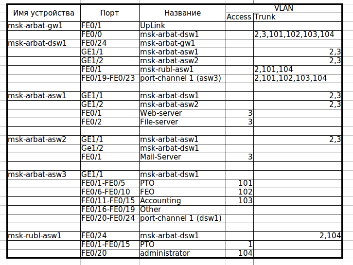
, . — . , — msk-arbat-asw2 asw1, . (, ) , msk-arbat-dsw1 msk-arbat-asw3, asw2. Asw3 Fa0/2 dsw1. :
msk-arbat-dsw1(config)#interface gi1/2
msk-arbat-dsw1(config-if)#description msk-arbat-asw2
msk-arbat-dsw1(config-if)#switchport trunk allowed vlan 2,3
msk-arbat-dsw1(config-if)#int fa0/2
msk-arbat-dsw1(config-if)#description msk-arbat-asw3
msk-arbat-dsw1(config-if)#switchport mode trunk
msk-arbat-dsw1(config-if)#switchport trunk allowed vlan 2,101-104
msk-arbat-asw2(config)#int gi1/2
msk-arbat-asw2(config-if)#description msk-arbat-dsw1
msk-arbat-asw2(config-if)#switchport mode trunk
msk-arbat-asw2(config-if)#switchport trunk allowed vlan 2,3
msk-arbat-asw2(config-if)#no shutdown
Do not forget to make all changes to the documentation!
Download the current version of the document.
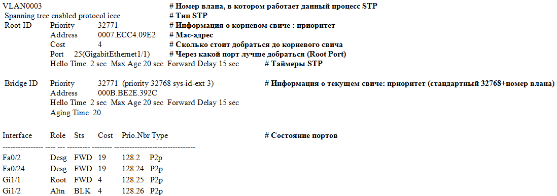
Now let's see how STP is self- tuned at the moment . We are only interested in VLAN0003, where we, judging by the scheme, loop.
msk-arbat-dsw1> en
msk-arbat-dsw1 # show spanning-tree vlan 3
, ? PVST+ (.. STP), , , . STP: ieee PVST, rstp — Rapid PVST, mstp . : , mac-, , , ( ), STP. - ( ). - , ( ):
- ,
- its role (Root- root port, Desg- designated port, Altn- additional, Back- reserve)
- its status (FWD-running, BLK-blocked, LIS-listening, LRN-training)
- route cost to root switch
- Port ID format: port priority. Port number
- connection type
So, we see that Gi1 / 1 is the root port, this gives some chance that there is a root switch on the other end of the link. We look under the scheme where the link leads: aha, a certain msk-arbat-asw1.
msk-arbat-asw1 # show spanning-tree vlan 3
And what do we see?
VLAN0003
 Spanning tree enabled protocol ieee
 Root ID Priority 32771
            Address 0007.ECC4.09E2
            This bridge is the root
            Hello Time 2 sec Max Age 20 sec Forward Delay 15 sec
Here it is, our root switch for VLAN0003.
Now look at the scheme. Earlier, in the ports state, we saw that dsw1 was blocking Gi1 / 2 port, thus breaking the loop. But is this the best solution? Of course not.Now our new network works exactly as the old traffic from asw2 goes only through asw1. Choosing a root router never needs to be left on the stupid STP conscience. Based on the scheme, the most optimal choice will be dsw1 as the root switch; thus, STP will block the link between asw1 and asw2. Now all this should be explained to the near protocol. And for him the main thing is what? Bridge ID. And it is no coincidence that it consists of two numbers. Priority is the very thing that is left to the network engineer, so that it can influence the result of the choice of the root switch. So, our task is to reduce (less-better, STP thinks) the priority of the necessary switch, so that it becomes Root Bridge. There are two ways:
1) to manually set a priority that is obviously lower than the current one:
msk-arbat-dsw1> enable
msk-arbat-dsw1 # configure terminal
msk-arbat-dsw1 (config) # spanning-tree vlan 3 priority?
<0-61440> bridge in increments of 4096
msk-arbat-dsw1 (config) # spanning-tree vlan 3 priority 4096
Now it has become root for Vlan 3, since it has a smaller Bridge ID:
msk-arbat-dsw1 # show spanning-tree vlan 3
VLAN0003
Spanning tree enabled protocol ieee
Root ID Priority 4099
Address 000B.BE2E.392C
This bridge is for
30 sec Forward Delay 15 sec
2) give a smart piece of iron to solve everything for you:
msk-arbat-dsw1 (config) # spanning-tree vlan 3 root primary
Checking:
msk-arbat-dsw1#show spanning-tree vlan 3
VLAN0003
Spanning tree enabled protocol ieee
Root ID Priority 24579
Address 000B.BE2E.392C
This bridge is the root
Hello Time 2 sec Max Age 20 sec Forward Delay 15 sec
, - . , ? - STP (.. , ), ( 4096, .. 8192). ? spanning-tree vlan n root secondary ( = -4096), , , - , , “”. , , asw2 asw1 ? STP . , . Sweet! : — , — .
msk-arbat-asw2#show spanning-tree vlan 3 VLAN0003 Spanning tree enabled protocol ieee Root ID Priority 24579 Address 000B.BE2E.392C Cost 4 Port 26(GigabitEthernet1/2) Hello Time 2 sec Max Age 20 sec Forward Delay 15 sec Bridge ID Priority 32771 (priority 32768 sys-id-ext 3) Address 000A.F385.D799 Hello Time 2 sec Max Age 20 sec Forward Delay 15 sec Aging Time 20 Interface Role Sts Cost Prio.Nbr Type ---------------- ---- --- --------- -------- -------------------------------- Fa0/1 Desg FWD 19 128.1 P2p Gi1/1 Altn BLK 4 128.25 P2p Gi1/2 Root FWD 4 128.26 P2p Now we will see how STP works: we go to the command line on the PTO1 laptop and start to ping our mail server endlessly (172.16.0.4). Ping is now following the route laptop-asw3-dsw1-gw1-dsw1 (well, it's clear why he does the hook - they are from different vlans) -asw2 server. And now let's work Godzilla from SimSity: break the connection between dsw1 and asw2, by pulling the wire out of the port (we notice the time needed to recalculate the tree).
Ping disappears, STP takes over, and for some 30 seconds the connection is restored. Godzilla was driven away, the fires were extinguished, the connection was repaired, we stuck the wire back. Pings disappear again for 30 seconds! Hmm, well, somehow not very fast, especially if you imagine that this happens, for example, in the processing center of a bank.
But we have the answer to slow PVST +! And this answer is - Fast PVST + (this is called, this is not a joke: Rapid-PVST). Let's see what he gives us. We change the type of STP on all switches in Moscow with a configuration mode command: spanning-tree mode rapid-pvst
Start the ping again, call Godzilla ... Hey, where are the missing pings? They are not, this is Rapid-PVST. As you probably remember from the theoretical part, this STP implementation, so to say, “underlay the straw” in case the main link falls, and switches to an additional (alternate) port very quickly, which we observed. Okay, stick the wire back. One lost ping. Not bad compared to 6-8, right?
EtherChannel
Remember, we took away their gigabit link from office workers and gave it to servers? Now they, poor things, are sitting on some hundred megabits, the last century! Let's try to expand the channel, and call for help EtherChannel. At the moment we have a connection from fa0 / 2 dsw1 to Gi1 / 1 asw3, disconnect the wire. We look, what ports we can use on asw3: aha, fa0 / 20-24 are free, it seems. Here we take them. On the dsw1 side, let fa0 / 19-23 be. We connect ports for EtherChannel among themselves. On asw3, we have configured something on the interfaces, usually in such cases, the configuration interface command default interface range fa0 / 20-24 is used, which resets the port settings (or ports, as in our case) to default. Packet tracer, alas, does not know such a good team, so in manual mode we remove each setting and extinguish the ports (better to do this, to avoid problems)
msk-arbat-asw3 (config) #interface range fa0 / 20-24
msk-arbat-asw3 (config-if-range) #no description
msk-arbat-asw3 (config-if-range) #no switchport access vlan
msk-arbat-asw3 (config-if-range) #no switchport mode
msk-arbat-asw3 (config-if-range) #shutdown
well now the magic team
msk-arbat-asw3 (config-if-range) # channel-group 1 mode on
same on dsw1:
msk-arbat-dsw1 (config) #interface range fa0 / 19-23
msk-arbat-dsw1 (config-if-range) # channel-group 1 mode on
we lifted asw3 interfaces, and voila: here it, our EtherChannel, was stretched already on 5 physical links. In the config, it will be reflected as interface Port-channel 1. Configure the trunk (repeat for dsw1):
msk-arbat-asw3 (config) #int port-channel 1
msk-arbat-asw3 (config-if) #switchport mode trunk
msk-arbat-asw3 (config-if) #switchport trunk allowed vlan 2,101-104
As with STP, there is some difficulty when working with etherchannel in the Packet Tracer. In principle, we can configure the scenario described above, but the performance test is a big question: after one of the ports in the group is disconnected, the traffic flows to the next, but as soon as you cut down the second port, the connection is lost and cannot be restored even after switching on ports.
Partly due to the reasons just stated, partly due to limited resources, we will not be able to fully address these issues and therefore leave most of it to self-study.
Release materials
New commutation plan
PT file with lab .
Device configuration
STP or STP
Link Layer Security
Channel aggregation
According to the established tradition, all the unanswered questions by unnamed readers of Habr are set in the blog of the cycle in LiveJournal .
Thanks for the video and help in preparing the article thanks eucariot
Source: https://habr.com/ru/post/143768/
All Articles