WebGLU: simplify working with WebGL
Once 3D in the browser was a big problem. They didn’t resort to creating dynamic 3D graphics in the browser: using pseudo-3D in SVG, building on canvas, using flash ... However, progress does not stand still: finally, all modern browsers began to support the lightweight version of OpenGL (OpenGL ES 2.0) - WebGL. This is a rather young technology, it is only a little more than a year old. However, it is already possible to estimate its power by all sorts of browser games and examples.
Due to the comparative youth of this technology, there are not so many manuals for working with it. You can read something about working with her here ( here - translation into Russian). Here you can learn something about the basics of WebGL.
To facilitate the work with WebGL, a number of libraries have been developed (although most of them are still quite raw). The application of one of them - webGLU - for the formation of a simple scene, illuminated by one source-lantern, and this article is devoted. Here you can see an example, and from here download the full archive to run it on your machine.
')
First, let me remind you a little about the difference between OpenGL and WebGL. Since WebGL is based on GLES, this technology is significantly inferior to OpenGL: it does not have many convenient extensions (ARB, etc.), there is no built-in support for lighting, and even GL_QUADS is not supported in it ... However, what can you do: no more technologies, Allowing to embody 3D on the web without third-party plug-ins is not.
Shaders are used to calculate the position of the vertices and their colors in the final image. In the simplest construction of three-dimensional scenes, shaders are called for each vertex with which they are associated. But more complex scenes cannot be described in this way. In this case, they resort to writing shaders that form the texture, which forms the final scene (an example can be seen here . Perhaps in the next article I will touch on this way of describing three-dimensional scenes.
The WebGLU library contains scant documentation and a few examples. This is not enough to complete the work with the library, so you have to read its source code. In addition, the library is quite raw, so sometimes you have to dig deeper into its code.
So, in order to get started with WebGLU, we need to enable the webglu.js script and initialize it:
$ W is the primary object of the WebGLU namespace. We will do most of the work with him. In addition to this object, there is an $ G object (GameGLU namespace), which simplifies working with scene control using the mouse and keyboard. There are some experimental functions in WebGLU (for example, CrazyGLU is for working with the pseudo-buffer of choice and some physics). All source files are loaded by WebGLU when running the corresponding functions (for example, the
After initializing the WebGLU, we can proceed to the creation of scene objects. To create an object, WebGLU provides the
flags - optional flags: by default they are equal to
So, for example, to create color coordinate axes, we will do this:
The default shader uses the following arrays to characterize each object vertex:
The corresponding variables in the shaders are named accordingly (except for the indices) (recall that the variables characterizing a particular vertex in the shader have an
The connection of shaders in WebGL is implemented using the
The light.json file itself looks like this:
Here name is the common name of the “material”; program → name - it seems to characterize the name of the program (perhaps the creator of WebGL assumed that several programs could be used for one material, but this parameter does not play a special role); shaders - used shaders with the path to them.
Variables that are common to each object or the entire system (with the
To set a non-standard material to an object, use the object property
Let's create this scene with WebGLU:
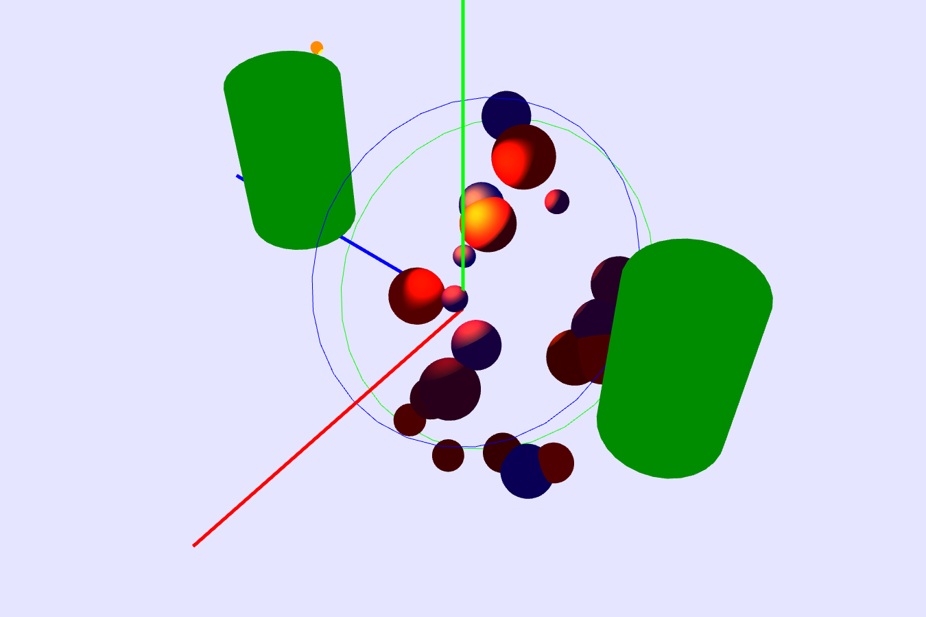
Here inheritance of objects is used: the main vertical cylinder inherits the second cylinder and the upper circle. That, in turn, inherits the lower circle and a set of multi-colored spheres of different sizes, placed randomly in a plane between two circles. The entire scene is illuminated by a single directional light source (orange “flashlight”), indicated by a small orange sphere.
To use the lighting, we definitely need to correctly calculate the normals to all the vertices that will be processed by our “lighter” shaders. We can draw the sphere using the
This method, as you will see later, is rather primitive: due to the fact that we don’t place vertices on the surface of the cylinder between its ends, the illumination for it is calculated incorrectly: if the “lantern” illuminates only the middle of the cylinder surface, without capturing its ends displayed unlit. To draw the cylinder correctly, you need to add additional intermediate vertices and fill the array of indices to correctly display the triangles. Another option is to draw a composite object (with children) from several rectangles, each of which consists of a set of triangles.
We will draw circles using the function
To be able to change the thickness of the lines that draw circles, we will need to override the
So, the objects we created. It was the turn to create shaders to calculate the lighting. In any OpenGL reference for calculating the final color of a vertex when illuminated by several sources, you can find the following formula:
Here
We can simplify this formula if we take into account that the usually diffuse and background color of the material coincide, the background color of the spotlight coincides with the diffuse color of the general background illumination, and the constant and linear attenuation coefficients can be omitted. As a result, we get such a fragment shader. In addition to calculating the vertex display coordinates, the vertex shader should recalculate, based on the model-specific matrix of the object, the vertex position in space and its normal orientation (this must be done, since we can move, scale, and rotate each object).
Now it remains for us to determine the properties of our “lantern”:
using
After we do all this, we animate the scene using the
Finally, I will say that the function of rotating the scene (more precisely, moving the camera around the scene) from WebGLU is not very convenient, so it’s worth defining your movement function. Here (and also at the address of the example specified at the very beginning) you can see what the final html file looks like.
The article turned out to be quite large, despite the fact that I did not mention working with the selection buffer (if we need to realize the identification of objects by a mouse click), the display of objects when mixing (and this is necessary for using the transparency component in the color of the object), clipping the “back” surfaces of figures and much more. I hope this article about WebGL is not the last (or maybe someone else will continue my initiative).
UPD: I tried to use the getObjectIDAt and usePicking functions from the crazyglu.js file to provide a choice, however, these attempts were not successful: the library is damp. Therefore, the function was written independently.
So, what is needed to implement the selection buffer.
First, we cannot use the
Second, we need to create a “global material” (
Making the choice is done according to the standard scheme: the object identifier (a 32-bit integer, preferably positive, it is possible and negative, but not equal to -1) is divided into bytes, which are converted into a floating-point number - an object color component. The float guarantees that rounding errors will not give the possibility of a random error (when the identifier a is converted to a ± 1). The shaders for displaying the selection buffer are so simple that I won't even bring them here.
Thirdly, you need to slightly change the code of the Objects.js file (to initialize identifiers by default), as well as Util.js (to save the contents of the drawing buffer after displaying its contents on the screen, otherwise the choice will not work).
Finally, we need to write a selection function that will draw objects into the selection buffer and get the color value under the cursor. To do this, after displaying all the objects, we save their “materials” into the
Due to the comparative youth of this technology, there are not so many manuals for working with it. You can read something about working with her here ( here - translation into Russian). Here you can learn something about the basics of WebGL.
To facilitate the work with WebGL, a number of libraries have been developed (although most of them are still quite raw). The application of one of them - webGLU - for the formation of a simple scene, illuminated by one source-lantern, and this article is devoted. Here you can see an example, and from here download the full archive to run it on your machine.
')
First, let me remind you a little about the difference between OpenGL and WebGL. Since WebGL is based on GLES, this technology is significantly inferior to OpenGL: it does not have many convenient extensions (ARB, etc.), there is no built-in support for lighting, and even GL_QUADS is not supported in it ... However, what can you do: no more technologies, Allowing to embody 3D on the web without third-party plug-ins is not.
Shaders are used to calculate the position of the vertices and their colors in the final image. In the simplest construction of three-dimensional scenes, shaders are called for each vertex with which they are associated. But more complex scenes cannot be described in this way. In this case, they resort to writing shaders that form the texture, which forms the final scene (an example can be seen here . Perhaps in the next article I will touch on this way of describing three-dimensional scenes.
The WebGLU library contains scant documentation and a few examples. This is not enough to complete the work with the library, so you have to read its source code. In addition, the library is quite raw, so sometimes you have to dig deeper into its code.
So, in order to get started with WebGLU, we need to enable the webglu.js script and initialize it:
<script type="text/javascript" src="./src/webglu.js"></script> … $W.initialize(); $ W is the primary object of the WebGLU namespace. We will do most of the work with him. In addition to this object, there is an $ G object (GameGLU namespace), which simplifies working with scene control using the mouse and keyboard. There are some experimental functions in WebGLU (for example, CrazyGLU is for working with the pseudo-buffer of choice and some physics). All source files are loaded by WebGLU when running the corresponding functions (for example, the
useControlProfiles(); function useControlProfiles(); loads ControlProfiles.js), so you do not need to load scripts manually besides webglu.js.After initializing the WebGLU, we can proceed to the creation of scene objects. To create an object, WebGLU provides the
$W.Object(type, flags) interface, where type is the type of the object (as in OpenGL):- $ W.GL.POINTS - each vertex is represented by a point,
- $ W.GL.LINES - each pair of vertices 2n-1 and 2n is connected by a line,
- $ W.GL.LINE_LOOP - all vertices are connected in order in segments with a closure to the first vertex,
- $ W.GL.LINE_STRIP - all vertices are connected by segments without closure,
- $ W.GL.TRIANGLES - each triple of vertices (in order) forms a triangle,
- $ W.GL.TRIANGLE_STRIP — vertices are connected in order by triangles,
- $ W.GL.TRIANGLE_FAN - vertices are connected by triangles around a common - first - vertices;
flags - optional flags: by default they are equal to
$W.RENDERABLE | $W.PICKABLE $W.RENDERABLE | $W.PICKABLE , however, if we draw an object that is a child, then $W.PICKABLE should be specified explicitly. In the simplest case, for each vertex of the object, you must specify a color, however, we are free to write a custom shader (which we will do later), which allows you to specify a common color for the entire object.So, for example, to create color coordinate axes, we will do this:
var originLines = new $W.Object($W.GL.LINES); originLines.vertexCount = 6; originLines.fillArray("vertex", [[0,0,0], [3,0,0], [0,0,0], [0,3,0], [0,0,0], [0,0,3]]); with ($W.constants.colors){ originLines.fillArray("color", [ RED, RED, GREEN, GREEN, BLUE, BLUE]); } The default shader uses the following arrays to characterize each object vertex:
- "Vertex" - the coordinates of the vertices,
- "Color" - colors of tops,
- "Normal" - normals to the vertices,
- "TexCoord" - coordinates of the texture at this vertex,
- “Wglu_elements” - indices of vertex coordinates (for complex objects).
The corresponding variables in the shaders are named accordingly (except for the indices) (recall that the variables characterizing a particular vertex in the shader have an
attribute ).The connection of shaders in WebGL is implemented using the
Material method. The only argument to this method is the path to the shader description JSON file. For example, our shaders that implement lighting are connected as follows: var lights = new $W.Material({path:$W.paths.materials + "light.json"}); The light.json file itself looks like this:
{ name: "light", program: { name: "light", shaders: [ {name:"light_vs", path:$W.paths.shaders+"light.vert"}, {name:"light_fs", path:$W.paths.shaders+"light.frag"} ] } } Here name is the common name of the “material”; program → name - it seems to characterize the name of the program (perhaps the creator of WebGL assumed that several programs could be used for one material, but this parameter does not play a special role); shaders - used shaders with the path to them.
Variables that are common to each object or the entire system (with the
uniform attribute) are associated with the corresponding JavaScript variables using the setUniformAction(n, f) method of the setUniformAction(n, f) object. The arguments of this method have the following value: n - the name of the variable in the shader (in the method it is specified as a string); f is a function of type function(u, o, m) , where u is an object uniform (), o is an object itself, m is a material. For example, binding the “color” parameter to the color of an object is performed as lights.setUniformAction('color', function(uniform, object, material){ $W.GL.uniform4fv(uniform.location, object.color); }); To set a non-standard material to an object, use the object property
setMaterial(mat) , where mat is the material we need. Since JavaScript allows you to add properties to already defined objects on the fly, we can easily make changes to objects to coordinate them with our shaders.Let's create this scene with WebGLU:
Here inheritance of objects is used: the main vertical cylinder inherits the second cylinder and the upper circle. That, in turn, inherits the lower circle and a set of multi-colored spheres of different sizes, placed randomly in a plane between two circles. The entire scene is illuminated by a single directional light source (orange “flashlight”), indicated by a small orange sphere.
To use the lighting, we definitely need to correctly calculate the normals to all the vertices that will be processed by our “lighter” shaders. We can draw the sphere using the
genSphere(n1,n2,rad) function of the genSphere(n1,n2,rad) library, but we will have to draw the cylinders ourselves. The easiest way to do this is to fill the side surface of the cylinder with connected triangles: function drawCylinder(R, H, n, flags){ var v = [], norm = []; var C = new $W.Object($W.GL.TRIANGLE_STRIP, flags); C.vertexCount = n * 2+2; for(var i = -1; i < n; i++){ var a = _2PI/n*i; var cc = Math.cos(a), ss = Math.sin(a); v = v.concat([R*cc, R*ss,0.]); v = v.concat([R*cc, R*ss,H]); norm = norm.concat([-cc, -ss, 0.]); norm = norm.concat([-cc, -ss, 0.]); } C.fillArray("vertex", v); C.fillArray("normal", norm); return C; } This method, as you will see later, is rather primitive: due to the fact that we don’t place vertices on the surface of the cylinder between its ends, the illumination for it is calculated incorrectly: if the “lantern” illuminates only the middle of the cylinder surface, without capturing its ends displayed unlit. To draw the cylinder correctly, you need to add additional intermediate vertices and fill the array of indices to correctly display the triangles. Another option is to draw a composite object (with children) from several rectangles, each of which consists of a set of triangles.
We will draw circles using the function
function drawCircle(R, n, w, flags){ var v = []; var C = new $W.Object($W.GL.LINE_LOOP, flags); C.vertexCount = n; for(var i = 0; i < n; i++){ var a = _2PI/n*i; v = v.concat([R*Math.cos(a), R*Math.sin(a),0.]); } C.fillArray("vertex", v); if(typeof(w) != "undefined") C.WD = w; else C.WD = 1.; C.draw = function(){ // var oldw = $W.GL.getParameter($W.GL.LINE_WIDTH); $W.GL.lineWidth(this.WD); this.drawAt( this.animatedPosition().elements, this.animatedRotation().matrix(), this.animatedScale().elements ); $W.GL.lineWidth(oldw); }; return C; } To be able to change the thickness of the lines that draw circles, we will need to override the
draw() function of this object (because the $W.GL.lineWidth(w) function sets the thickness of the w line globally - until the next call to this function). If you change the $W.GL.LINE_LOOP of this object to $W.GL.POINTS , the circles will be drawn with dots. The size of the points will depend on the property of the WD object due to the fact that we use for it the “material” points, which indicates gl_PointSize = WD; Here you can see the fragment shader code for displaying points of different sizes, and here - the vertex shader.So, the objects we created. It was the turn to create shaders to calculate the lighting. In any OpenGL reference for calculating the final color of a vertex when illuminated by several sources, you can find the following formula:
result_Color = mat_emission + lmodel_ambient * mat_ambient Sum_i(D * S * [l_ambient * mat_ambient + max{dot(L,n),0}*l_diffuse*mat_diffuse + max{dot(s,n),0}^mat_shininess * l_specular * mat_specular ) Here
- result_Color - the final color of the vertex,
- mat_X - material properties
- l_X - properties of the i-th light source
- X:
- emission - emitted light (i.e. material is a source of light),
- lmodel_ambient - the general diffused light of the lighting model (does not depend on the sources, i.e. it is background light)
- ambient - background light (the color of the material outside the light sources, the diffuse light component of the i-th light source)
- D is the light attenuation coefficient, D = 1 / (kc + kl * d + kq * d ^ 2),
- d is the distance from the source to the top,
- kc is the constant attenuation coefficient (“gray filter”),
- kl is the linear attenuation coefficient,
- kq is the quadratic attenuation coefficient,
- S is the searchlight effect, calculated as follows:
= 1 if the light source is not a searchlight (infinitely remote parallel beam),
= 0 if the source is a searchlight, but the top is outside the radiation cone,
= max {dot (v, dd), 0} ^ GL_SPOT_EXPONENT in other cases, here v is the normalized vector from the searchlight (GL_POSITION) to the top, dd (GL_SPOT_DIRECTION) is the orientation of the searchlight - L = -v (normalized vector from the vertex to the source),
- n is the normal to the vertex
- diffuse - diffused light, does not depend on the angle of incidence / reflection,
- s is the normalized vector equal to the sum of L and the vector from the top to the eye,
- shininess - the degree of gloss (from 0 to 128, the more, the more brilliant the surface is),
- specular - the color of the mirror component.
We can simplify this formula if we take into account that the usually diffuse and background color of the material coincide, the background color of the spotlight coincides with the diffuse color of the general background illumination, and the constant and linear attenuation coefficients can be omitted. As a result, we get such a fragment shader. In addition to calculating the vertex display coordinates, the vertex shader should recalculate, based on the model-specific matrix of the object, the vertex position in space and its normal orientation (this must be done, since we can move, scale, and rotate each object).
Now it remains for us to determine the properties of our “lantern”:
light = { position: [0.,2.,1.5], target: [0.,0.,-2.], color: [1.,.5,0.,1.], fieldAngle: 60., exponent: 5., distanceFalloffRatio: .02 }; using
setUniformAction(…) to connect the properties of the “flashlight” and the properties of objects with variable shaders and set individual properties for each object using this “material”.After we do all this, we animate the scene using the
$W.start(T); function $W.start(T); where T is the minimum interval between scene rendering. If our scene is too complex, we will have to draw it after each change manually using the $W.util.defaultUpdate(); functions $W.util.defaultUpdate(); and $W.util.defaultDraw(); . These functions do not affect the compilation of shaders (which should be performed only when making drastic changes to the shaders themselves), so our scene will “freeze” only at the time of initial loading (during initialization), and also slow down a little when the window is resized.Finally, I will say that the function of rotating the scene (more precisely, moving the camera around the scene) from WebGLU is not very convenient, so it’s worth defining your movement function. Here (and also at the address of the example specified at the very beginning) you can see what the final html file looks like.
The article turned out to be quite large, despite the fact that I did not mention working with the selection buffer (if we need to realize the identification of objects by a mouse click), the display of objects when mixing (and this is necessary for using the transparency component in the color of the object), clipping the “back” surfaces of figures and much more. I hope this article about WebGL is not the last (or maybe someone else will continue my initiative).
UPD: I tried to use the getObjectIDAt and usePicking functions from the crazyglu.js file to provide a choice, however, these attempts were not successful: the library is damp. Therefore, the function was written independently.
So, what is needed to implement the selection buffer.
First, we cannot use the
$W.start(p) function, otherwise we run the risk of “running into” updating the image with a timer when we write to the selection buffer. Therefore, we need to take care of drawing the scene after each change in it.Second, we need to create a “global material” (
MatPick ) for the selection buffer and initialize it, as well as initialize the buffer itself: // "" MatPick = new $W.Material({path:$W.paths.materials + "pick.json"}); MatPick.setUniformAction('pickColor', function(uniform, object, material){ var colr = [0.,0.,0.,0.]; var id = object.id; for(var i = 0; i < 4; i++){ colr[i] = (id & 0xff)/256.; id >>= 8; } $W.GL.uniform4fv(uniform.location, colr); } ); // try{ $W.pickBuffer = new $W.Framebuffer(); $W.pickBuffer.attachTexture($W.GL.RGBA, $W.canvas.width, $W.canvas.height, $W.GL.COLOR_ATTACHMENT0); $W.pickBuffer.attachRenderbuffer($W.GL.DEPTH_COMPONENT16, $W.canvas.width, $W.canvas.height, $W.GL.DEPTH_ATTACHMENT); }catch (e) { console.error(e); } Making the choice is done according to the standard scheme: the object identifier (a 32-bit integer, preferably positive, it is possible and negative, but not equal to -1) is divided into bytes, which are converted into a floating-point number - an object color component. The float guarantees that rounding errors will not give the possibility of a random error (when the identifier a is converted to a ± 1). The shaders for displaying the selection buffer are so simple that I won't even bring them here.
Thirdly, you need to slightly change the code of the Objects.js file (to initialize identifiers by default), as well as Util.js (to save the contents of the drawing buffer after displaying its contents on the screen, otherwise the choice will not work).
Finally, we need to write a selection function that will draw objects into the selection buffer and get the color value under the cursor. To do this, after displaying all the objects, we save their “materials” into the
oldmat array, and when drawing the selection buffer, temporarily change all the “materials” to our MatPick , fill the buffer and get the color value at the desired point. And already by the color value we define the object identifier (or its absence, if id == - 1): function pick(X,Y){ // var ccolr = $W.GL.getParameter($W.GL.COLOR_CLEAR_VALUE); var blend = $W.GL.getParameter($W.GL.BLEND); if(blend) $W.GL.disable($W.GL.BLEND); $W.GL.clearColor(1., 1., 1., 1.); // "-1" $W.pickBuffer.bind(); // "" $W.util.defaultUpdate(); $W.util.clear(); $W.util.setupMatrices(); for (var i = 0; i < $W.objects.length; i++) { $W.objects[i].material = MatPick; // "" } $W.util.defaultDraw(); // for (var i = 0; i < $W.objects.length; i++) { $W.objects[i].material = oldmat[i]; // "" } var pix = new Uint8Array(4); $W.GL.readPixels(X,$W.canvas.height-Y,1,1,$W.GL.RGBA, $W.GL.UNSIGNED_BYTE, pix); $W.pickBuffer.unbind(); // if(blend) $W.GL.enable($W.GL.BLEND); $W.GL.clearColor(ccolr[0],ccolr[1],ccolr[2],ccolr[3]); var id = pix[0]+(pix[1]<<8)+(pix[2]<<16)+(pix[3]<<24); delete pix; var str = "X=" + X + ", Y=" + Y+ ", ID="+id; alert(str); } </code> <br><br> : . <br><br> : google-chrome ( ). Source: https://habr.com/ru/post/143680/
All Articles