433MHz radio channel and time synchronization from GPS
 Good day!
I want to share the experience of creating a single time synchronization system within an apartment / office with elements of the old school and post-apocalypse.
Always wanted to make a clock that does not need time correction. As a student, I tried to assemble a receiver of time synchronization signals on a DV ( DCF77 ), I even sawed the quartz I needed. But the signal from Germany reached a weak one, and the serious antenna was obtained.
Then came the ability to synchronize from GPS. At one time, I acquired an RS232 GPS module that provides information about the coordinates in NMEA , which I connected to a black and white PALM m105 and was happy about the PathAway program. But there was no progress on the spot, other tasks appeared and the GPS module lain on the shelf until now.
The lack of time synchronization from GPS is the need to position the receiver in direct line of sight of at least one satellite, which is not always acceptable in the context of hours. In connection with this, the idea of wireless synchronization appeared, i.e. the receiver is located on the window sill and distributes the exact time to the nearby wishing radio channel. To fence the duplex channel so that the time is synchronized on demand, found it unnecessary. The GPS receiver itself transmits synchronization with a specified period.
')
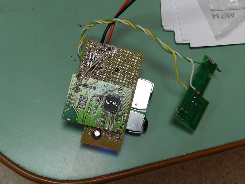
As a radio channel used lying nodes dead car alarm (operating frequency 433 MHz). After updating the network equipment in the home office (provider), the domestic production of the LightCOM S100 was released, the management of which was based on the PIC18F452 processor, so no additional financial costs were foreseen.
To avoid further questions below, a device with a GPS receiver and a synchronization transmitter will be called a transmitter, and a clock with a synchronization receiver will be called a receiver.
Historically, I used to assemble circuits on circuit boards using MGTF.
So supporters of LUT please do not kick. Having drunk the processor stuck it to the installer. I don’t cite the transmitter circuitry and 2 hours, there are pinouts in the code.
So let's start with the transmitter:
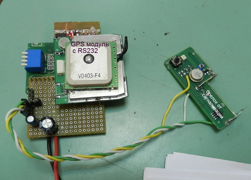
The system of functioning of the transmitter is simple. We accept the USART PICa NMEA port of the offer and get data from there about the current time, date and relevance of this data. As soon as the synchronization period comes up (I have 4 minutes) - we transmit all this on the air. From the features of the transmitter circuit, I note the following:
- the circuit is powered by 5 volts, while the key fob wants 12 volts. I had to fence the diode-capacitor voltage doubler.
- in order not to make a level converter from RS232 to TTL, I opened the GPS module and output the TTL signal to the output RS232 converter.
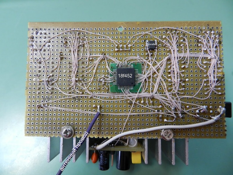
Here is the back of the transmitter:
The peculiarity of car alarm radio exchange is the need to transmit so-called. the preamble is a meander of a certain duration for the output of receiving chains and AGC to a stable mode (you can read the specification on keeloq on the Internet). So, by transferring the preamble, we transfer the necessary bytes and at the end - the checksum byte to reduce the likelihood of errors on the receiving side.
The first synchronization receiver (clock) made on the basis of the indicator from the written-off cash terminal:

The peculiarity of this watch, and any that use external synchronization, is the absence of the need for its own accurate clock (RTC), usually implemented on chips with 326868 quartz or available on board most modern microcontrollers. In principle, the same clock can be made on the RC-generator. The main thing is that the accuracy is not significantly floated during the synchronization period.

The clock scheme is trivial. The indicator is connected in the 4-bit data bus mode. The input from int0 PICa is the output from the car alarm receiver. To implement the display of large numbers on the 2-line text indicator, we had to use client-changeable characters in cgram. Design characters honestly stole.
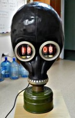
Having found the IN-14 lamps in the storeroom, which are a little younger than me, I could not resist creating the second hours:
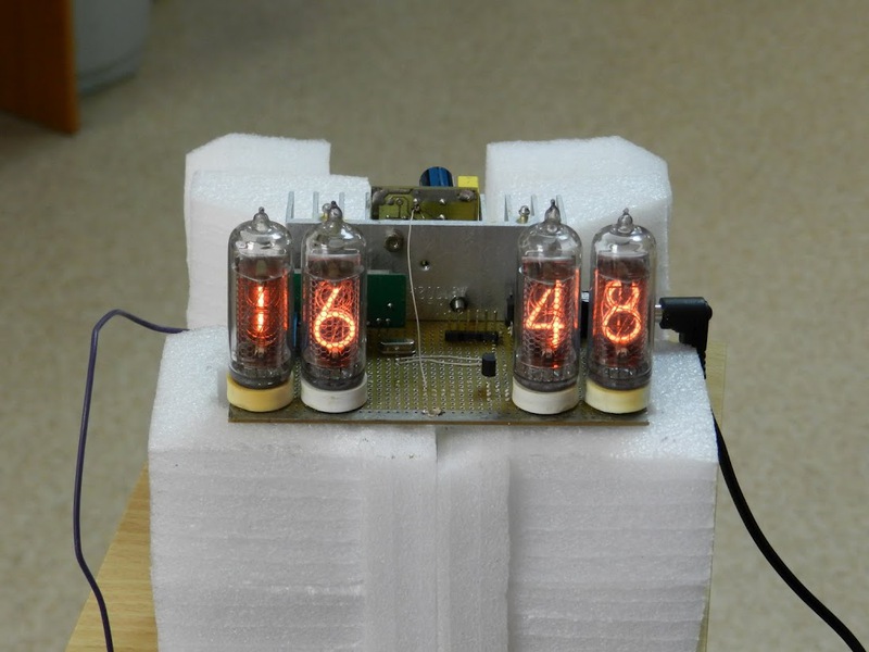
Circuitry, there are also no special delights, but still:
- the indication is static (the benefit is there are a lot of free conclusions from PICa and even 155ID1 is enough).

- I had to hang basking elements on the radiator
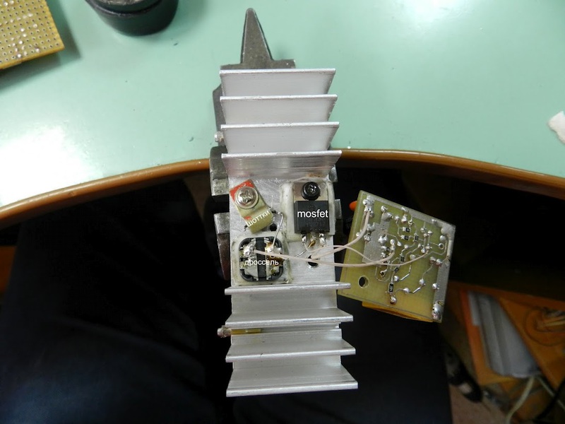
voltage multiplier (180V according to the specification for IN14 lamps)

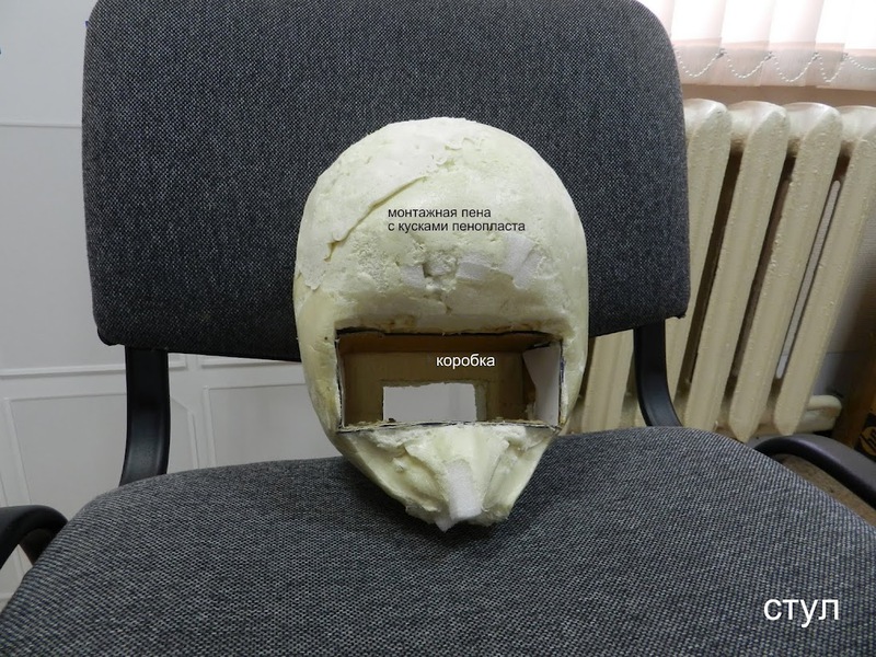
Just a couple of design moves to emphasize the post-apocalyptic plot:
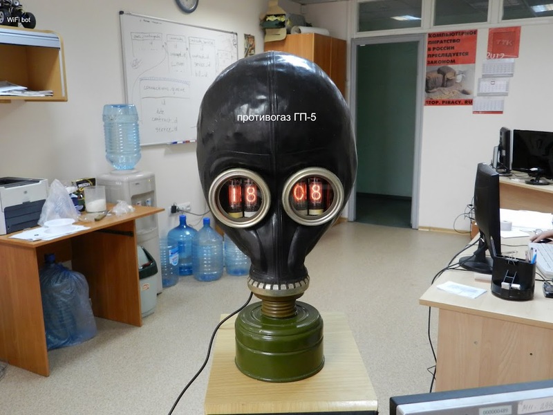
- I decided to pack the watch in a gas mask, for which I had to make a mannequin of the head out of polyurethane foam and pieces of foam:
- added glitches to the display (show on video)
- added a buzzer to create sounds of a working dosimeter
- glitches and a dosimeter signal are generated using the rand () function in c18, the seed of which is formed with the participation of atmospheric noise taken from the receiver output.
- the switching of minutes is accompanied by the switching off of the multiplier and the beautiful extinction of the indication
Finished watch number 2:
Video of work:
More videos:
I wrote for the first time on c18. Previously, under the PIC wrote in assembler.
Sources
Source: https://habr.com/ru/post/143568/
All Articles