Correct implementation of the PID regulator difference scheme
The PID controller is the simplest controller with effective analog hardware implementations, and therefore is used most widely. For its work, it is necessary to adjust 3 coefficients for a specific object, allowing to select the regulatory process according to requirements. Possessing a simple physical meaning and simple mathematical writing, it is widely used and often in temperature regulators, gas flow regulators and other systems where it is required to maintain a certain parameter at a given level, with possible transitions between different specified levels. Of course, there are more complex regulators that allow more accurate and fast and with less overshoot to go to the specified parameters, as well as taking into account the nonlinearity or hysteresis of the regulated object, but they have greater computational complexity and more difficult to configure.
Despite its simplicity, both in physical sense and in mathematical writing:
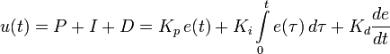
in the software implementation of the PID controller, errors are often made that are found even in verified automation devices.
Moreover, it is extremely easy to check the quality of the implementation of the PID controller.
')
Consider the simplest example: the thermostat. A quick, low-inertial, low-power object is best suited to test its quality. The classic of the genre: a regular 100W bulb with a thin thermocouple (HA) screwed to it. And the first thing to check the PID controller is to degrade the PID to just the P controller. That is, the coefficients of the integral and differential set at zero, and proportional set at a maximum.
Turn on the regulator, check: the current temperature is 22 degrees, the setting is 16 degrees. The light is off. We are starting to start increasing the set point: 16.1, 16.3, 16.7, 18 ... 19 ... the light bulb has caught fire. How?! Where from ?! Stop - turned off. So, we met with the first classical PID implementation error .
A small mathematical digression: remember once again the integral record indicated above. We implement it programmatically, which means discrete. That is, with enviable regularity, we measure the input quantity, compare it with the setpoint, calculate the effect, issue it, repeat. So, it is necessary to move from an integral form to a finite difference scheme. At the transition is usually used the transition "in the forehead":

where
The use of a direct formula will require a 1x count and store the integral of mismatches over a long period, and 2x requires high precision floating point operation (since the integral coefficient Ki is always <1), or division operations (representing a 1 / Ki factor) are large bit depth. All this requires computational resources, of which, in embedded ones, as a rule, is very limited ... Therefore, instead of implementing a direct scheme, they implement a recurrent formula:

the use of the recurrent formula allows to reduce the amount of calculations and the bit depth of intermediate values.
So back to our regulator. So, there is an adjustable object: a light bulb. To control the power supplied to it, use a simple approach: the power supply network (220V 50Hz) is supplied through a triac to the load. The triac at the moment of transition of the half-wave through zero turns off, and remains off until a signal is sent to the control electrode. Thus, the sooner we give a control signal after the start of the half-wave, the more energy from this half-wave will reach the controlled object. Having correctly calculated the time for the linearity of the area of a half-wave from time X to the end of the half-wave, we are able to output power from 0 to 100% with the accuracy with which the linearization table was calculated.
So, we can produce power from 0 to 100%. In real objects, it is often impossible to produce 100% of the power - for example, it is burning through the blowout of the heating element. Therefore, all devices have a minimum and maximum output power setting for an object.
So, after calculating
After that, the calculated Un is the required output power for the current moment. Ta-dam! It is this implementation that creates the error described above.
The reason is trivial: at the moment of transition from the discrete to the finite difference scheme, we “put out” the operation of calculating the integral, and at each step we add the derivative to the accumulated sum
Conclusion # 1 : the calculation of U (n) cannot be limited. To limit the power supplied to the output device, you must have a separate variable.
Now, when we started Urn, for limited capacity, we reload, we continue to test.
Turn on the regulator, check: the current temperature is 22 degrees, the setting is 16 degrees. The light is off.
We begin to add the set point: 16.1, 16.4, 17, 18, 20, 22, 24 (oops! Lit up! Hurray!), 28, 30, 40, 60 ... Beauty! Works!
We observe the process - it turned out about 60, dangles a bit back and forth, but it keeps. It seems everything is beautiful. Exhale, check the control from the PC: set 600 degrees. And ... The light goes out. How so? Is the setting 600 current 60 and the light is off?
While we wait and slowly realize that we clearly ran into some kind of “Classic Jamb №2” ™ the light bulb slowly inflames, goes to 100% power, and so it remains - it can not give out 600 degrees.
We return again to our difference scheme.
Conclusion # 2 : calculations should be performed with correct overflow support. Overflowed? Limit the limit number, so do not wrap.
So, we increased the capacity of U (n), retranslated, stitched, run. The light bulb is still not completely cold, it is 80 degrees, the setpoint is still the same 600. The light bulb lights up ... and it goes out. Ignites and goes out. How so? Setting 600, the light bulb 80 - and supports quite a 80 of them! How is that?! Obviously, we got out bug number 3 .
And again the lyrical and mathematical digression. So, there is our difference scheme:
Often found solution: everything is zeroed, the setpoint is read from the flash memory of the setpoint, we wait for 1 polling cycle, and we read X (0). Here, zero is ready, now we are working. And ... And not right. Why? Because the recurrent formula is repelled by changes in the discrepancy. And by initializing zero and loading the current values, we lost the starting conditions. Everything - instead of maintaining the absolute value of the temperature at a level equal to the absolute setpoint, the controller begins to keep the temperature equal to the starting one plus the difference of the setpoint. That is, it was 80 degrees and the setpoint 200, the device was turned on - it holds 80. The setpoint was changed to 240 - it began to hold 120.
Correct initialization of the difference scheme: zero _into all_. I.e
And at the first cycle of calculations, we seem to have a jump in the setpoint and the current value:
Now the scheme works correctly.
Conclusion number 3 : correctly initialize the starting conditions.
Is it right? Well, well ... Once again ... We set the setpoint 20. We are waiting for cooling ... Turn off. Turn on. So, beauty: the current 20, setting 20. We set abruptly 600. I went to bask. 100, 120 ... set the setpoint 20. Disconnected, went to cool. We are waiting for a bit (120 ... 110 ... 100 ... 90 ... 80 ...) and set the setpoint to 100. I went to warm up ... 105 degrees, turned off. Stop. And why does it keep 105? We only have a proportional component now. When correctly implemented from the physical meaning of the process, the oscillating process cannot keep the set point higher than specified. Strictly below. And holds 5 degrees more than asked. This is observed Prikol number 4 .
So, we recall that we had above: Conclusion # 2: U (n) cannot be limited. And Conclusion number 3: in case of overflow, you still have to limit it. Yes Yes. Otherwise, the “operating point” is shifted for a limited time. What to do? Increase the bit depth? Well, if you have enough computing power. Is it necessary? Actually, what's wrong, that we have U (n) = 9999.99, and not 29999.99? In general, only that we have lost 20,000. But now, for work, we just and so need to tumble in just 100% of the power, right? Right. This means that there are no problems with the restriction in the regiment, as long as we do not depart from the limit. Thus, in the event of overflow, a flag must be set, and when, for example, half of the range is reached (that is, U (n) has dropped below 5000.00 after 9999.9), the circuit will be reinitialized again. That is, discard the story, say that n = 0 and see above. Conclusion No. 3. The inquisitive mind has already realized that in the case of a complete scheme, when all three components are not zero, zeroing the iterative process in the process, we including zeroing the accumulated integral of the integral component. However, due to the fact that we reset to zero significantly in advance, he will have time to dig up during the time the additional balance is generated. And it is not entirely correct to save the integral on “large” sections, since the goal of the integral component is to “choose” a discrepancy that the proportional component cannot work out separately.
Conclusion No. 4 : if for some reason U (n) was limited, the circuit should be reinitialized as soon as it seemed that the circuit had returned to its normal state.
In the next issue : is it really necessary to implement a difference scheme? Detailed implementation of a direct discrete circuit with simple and understandable tunable coefficients with direct physical meaning, which easily computes a control action with a frequency of 25 Hz on the ADuC847 processor (fast 8-bit controller, with the core 8051), leaving more processor time for other processes .
(The pictures with the image of formulas are taken from the article PID-regulator in Wikipedia)
Despite its simplicity, both in physical sense and in mathematical writing:
in the software implementation of the PID controller, errors are often made that are found even in verified automation devices.
Moreover, it is extremely easy to check the quality of the implementation of the PID controller.
')
Consider the simplest example: the thermostat. A quick, low-inertial, low-power object is best suited to test its quality. The classic of the genre: a regular 100W bulb with a thin thermocouple (HA) screwed to it. And the first thing to check the PID controller is to degrade the PID to just the P controller. That is, the coefficients of the integral and differential set at zero, and proportional set at a maximum.
Turn on the regulator, check: the current temperature is 22 degrees, the setting is 16 degrees. The light is off. We are starting to start increasing the set point: 16.1, 16.3, 16.7, 18 ... 19 ... the light bulb has caught fire. How?! Where from ?! Stop - turned off. So, we met with the first classical PID implementation error .
A small mathematical digression: remember once again the integral record indicated above. We implement it programmatically, which means discrete. That is, with enviable regularity, we measure the input quantity, compare it with the setpoint, calculate the effect, issue it, repeat. So, it is necessary to move from an integral form to a finite difference scheme. At the transition is usually used the transition "in the forehead":
where
E(n) = X(n) - X0(n) - that is, the value of the mismatch between the current and the specified value of the adjustable parameter.The use of a direct formula will require a 1x count and store the integral of mismatches over a long period, and 2x requires high precision floating point operation (since the integral coefficient Ki is always <1), or division operations (representing a 1 / Ki factor) are large bit depth. All this requires computational resources, of which, in embedded ones, as a rule, is very limited ... Therefore, instead of implementing a direct scheme, they implement a recurrent formula:
the use of the recurrent formula allows to reduce the amount of calculations and the bit depth of intermediate values.
So back to our regulator. So, there is an adjustable object: a light bulb. To control the power supplied to it, use a simple approach: the power supply network (220V 50Hz) is supplied through a triac to the load. The triac at the moment of transition of the half-wave through zero turns off, and remains off until a signal is sent to the control electrode. Thus, the sooner we give a control signal after the start of the half-wave, the more energy from this half-wave will reach the controlled object. Having correctly calculated the time for the linearity of the area of a half-wave from time X to the end of the half-wave, we are able to output power from 0 to 100% with the accuracy with which the linearization table was calculated.
So, we can produce power from 0 to 100%. In real objects, it is often impossible to produce 100% of the power - for example, it is burning through the blowout of the heating element. Therefore, all devices have a minimum and maximum output power setting for an object.
So, after calculating
U(n) by the above formula, one more constraint is added:if Un < Umin then Un := Umin; if Un>Umax then Un := Umax;After that, the calculated Un is the required output power for the current moment. Ta-dam! It is this implementation that creates the error described above.
The reason is trivial: at the moment of transition from the discrete to the finite difference scheme, we “put out” the operation of calculating the integral, and at each step we add the derivative to the accumulated sum
U(n-1) . By imposing a restriction on it, we actually zero the entire computed integral. (Well, not how many are reset, how much we lead to the range of 0-100, which in this case is insignificant). Thus, we differentiate the PID controller, and the differential-accelerator remains. What actually looks like a simple differential controller is that the power is supplied in proportion to the change in the setpoint or controlled variable, and not in proportion to the difference between the setpoint and the controlled variable.Conclusion # 1 : the calculation of U (n) cannot be limited. To limit the power supplied to the output device, you must have a separate variable.
Now, when we started Urn, for limited capacity, we reload, we continue to test.
Turn on the regulator, check: the current temperature is 22 degrees, the setting is 16 degrees. The light is off.
We begin to add the set point: 16.1, 16.4, 17, 18, 20, 22, 24 (oops! Lit up! Hurray!), 28, 30, 40, 60 ... Beauty! Works!
We observe the process - it turned out about 60, dangles a bit back and forth, but it keeps. It seems everything is beautiful. Exhale, check the control from the PC: set 600 degrees. And ... The light goes out. How so? Is the setting 600 current 60 and the light is off?
While we wait and slowly realize that we clearly ran into some kind of “Classic Jamb №2” ™ the light bulb slowly inflames, goes to 100% power, and so it remains - it can not give out 600 degrees.
We return again to our difference scheme.
U(n) = U(n-1) + Kp*(dE + ...) . The difference in residual multiplied by the coefficient of proportionality is added to the current calculated value of the impact. We had a setpoint of 60, a temperature of 60, that is, the residual is zero. The output power was also zero. And here at once, abruptly, the setpoint was increased to 600 degrees. the discrepancy sharply became 540 degrees, multiplied by the proportionality coefficient ... and flew out for the storage capacity U (n). Do not laugh, use math from a fixed point, instead of a floating point. With a difference of 540 degrees and work through 1/16, with a proportionality coefficient of 20, we get ... 540 * 20 * 16 = 172800, and if we have 16-bit U (n), and even sign, then in fact we got A300h = −8960. Opachki. Instead of a big plus - such a tangible minus.Conclusion # 2 : calculations should be performed with correct overflow support. Overflowed? Limit the limit number, so do not wrap.
So, we increased the capacity of U (n), retranslated, stitched, run. The light bulb is still not completely cold, it is 80 degrees, the setpoint is still the same 600. The light bulb lights up ... and it goes out. Ignites and goes out. How so? Setting 600, the light bulb 80 - and supports quite a 80 of them! How is that?! Obviously, we got out bug number 3 .
And again the lyrical and mathematical digression. So, there is our difference scheme:
U(n) = G(U(n-1), dE(n)) . Once again: the new impact value is the sum of the past exposure and some impact, depending on the difference of the residual at the current moment and the previous one. And what is the previous point? And what is the previous moment of the previous one? Well, remember the school. Proof by induction. If you can build a proof for K + 1, assuming that the proof for K is true, And to prove separately what is true for K = 0, then the proof is true. So, how do we count U (0)?Often found solution: everything is zeroed, the setpoint is read from the flash memory of the setpoint, we wait for 1 polling cycle, and we read X (0). Here, zero is ready, now we are working. And ... And not right. Why? Because the recurrent formula is repelled by changes in the discrepancy. And by initializing zero and loading the current values, we lost the starting conditions. Everything - instead of maintaining the absolute value of the temperature at a level equal to the absolute setpoint, the controller begins to keep the temperature equal to the starting one plus the difference of the setpoint. That is, it was 80 degrees and the setpoint 200, the device was turned on - it holds 80. The setpoint was changed to 240 - it began to hold 120.
Correct initialization of the difference scheme: zero _into all_. I.e
X(0) = 0, X0(0) = 0. U(0) = 0. E(0)=X(0)-X0(0)=0.And at the first cycle of calculations, we seem to have a jump in the setpoint and the current value:
X(1) = 80. X0(1)=200. U(1) = U(0)+Kp*(E(1)-E(0)) = U(0)+Kp*(X(1)-X0(1)-E(0)) = 0 + 20*(200 - 80 - 0) = 2400Now the scheme works correctly.
Conclusion number 3 : correctly initialize the starting conditions.
Is it right? Well, well ... Once again ... We set the setpoint 20. We are waiting for cooling ... Turn off. Turn on. So, beauty: the current 20, setting 20. We set abruptly 600. I went to bask. 100, 120 ... set the setpoint 20. Disconnected, went to cool. We are waiting for a bit (120 ... 110 ... 100 ... 90 ... 80 ...) and set the setpoint to 100. I went to warm up ... 105 degrees, turned off. Stop. And why does it keep 105? We only have a proportional component now. When correctly implemented from the physical meaning of the process, the oscillating process cannot keep the set point higher than specified. Strictly below. And holds 5 degrees more than asked. This is observed Prikol number 4 .
So, we recall that we had above: Conclusion # 2: U (n) cannot be limited. And Conclusion number 3: in case of overflow, you still have to limit it. Yes Yes. Otherwise, the “operating point” is shifted for a limited time. What to do? Increase the bit depth? Well, if you have enough computing power. Is it necessary? Actually, what's wrong, that we have U (n) = 9999.99, and not 29999.99? In general, only that we have lost 20,000. But now, for work, we just and so need to tumble in just 100% of the power, right? Right. This means that there are no problems with the restriction in the regiment, as long as we do not depart from the limit. Thus, in the event of overflow, a flag must be set, and when, for example, half of the range is reached (that is, U (n) has dropped below 5000.00 after 9999.9), the circuit will be reinitialized again. That is, discard the story, say that n = 0 and see above. Conclusion No. 3. The inquisitive mind has already realized that in the case of a complete scheme, when all three components are not zero, zeroing the iterative process in the process, we including zeroing the accumulated integral of the integral component. However, due to the fact that we reset to zero significantly in advance, he will have time to dig up during the time the additional balance is generated. And it is not entirely correct to save the integral on “large” sections, since the goal of the integral component is to “choose” a discrepancy that the proportional component cannot work out separately.
Conclusion No. 4 : if for some reason U (n) was limited, the circuit should be reinitialized as soon as it seemed that the circuit had returned to its normal state.
In the next issue : is it really necessary to implement a difference scheme? Detailed implementation of a direct discrete circuit with simple and understandable tunable coefficients with direct physical meaning, which easily computes a control action with a frequency of 25 Hz on the ADuC847 processor (fast 8-bit controller, with the core 8051), leaving more processor time for other processes .
(The pictures with the image of formulas are taken from the article PID-regulator in Wikipedia)
Source: https://habr.com/ru/post/143388/
All Articles