Automatic staircase lighting with Arduino
 Good day! In this post I want to share with the habro community about how I happened to make an automatic staircase lighting in my two-story cottage. I will begin with a small sad retreat.
About four months ago, returning from work in complete darkness, I did not slip well and broke two metatarsal bones (fingers) on my left foot. For a whole month I had to fall in bed, as stepping on my foot was incredibly painful. Then he was limp without a plaster for another half month (those who had fractures would immediately understand me). After this sad story, I began to think about the automation of staircase lighting. After playing a little with search queries, I found a very simple solution for myself on this blog , just based on my favorite Arduino microcontroller. The scheme did not cause any difficulties, but it scared the number and length of the wires that I had to mount. Before that, I did not do anything like that. Buying ready-made solutions or hiring someone is expensive. Within a month I ordered the necessary components and unhurriedly assembled it on my stairs in a few days. Everyone who is interested in what came of it, welcome under the cut (careful traffic)!
Components
I will give an approximate cost of all the components that were used in the work. Most of the components purchased in the shops of my city are therefore all in rubles.
| Arduino Pro Mini | 300 r |
| Ultrasonic Module HC-SR04 Distance Sensor - 2 pcs | 230 r |
| LED driver M5450 | 88 r |
| Voltage Regulator L78M05CV | 26 r |
| Photoresistor FR-764 | 16 r |
| Cable channel 20x10 mm - 10 M | 100 r |
| Wire 2x0.12 - 100 M (with a margin for tapes) | 190 r |
| Wire 4x0.12 - 20 M (for sensors) | 60 r |
| LED Strip LSP0603W15 White - 17 pieces of 30 cm | 1020 r |
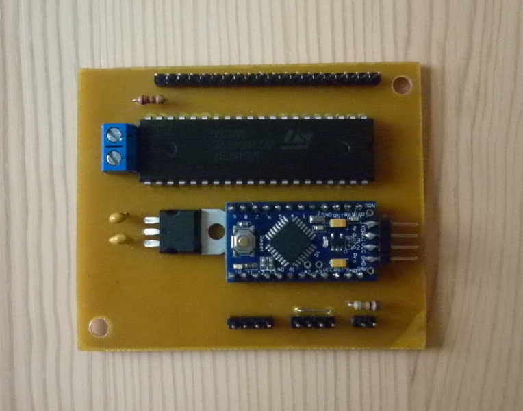
| Small things: textolite 15x15 cm, ferric chloride, drill 0.9 mm, PLS pin connectors, BLS connectors, heat shrink tubing, capacitors and resistors | 200 r |
| The power supply unit 12B (it is the case) from the Parus 4 alarm system | Is free |
Prototype
I debugged the firmware for Arduino, like everything else, on a breadboard using ordinary LEDs.
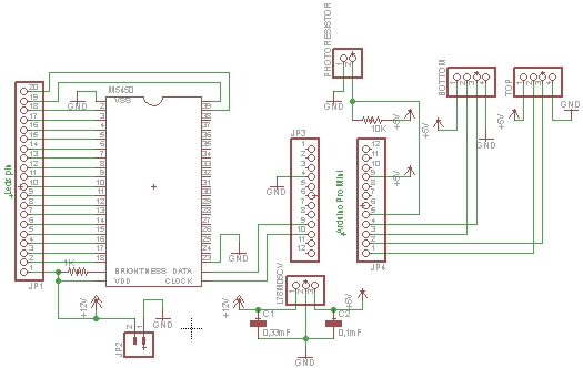
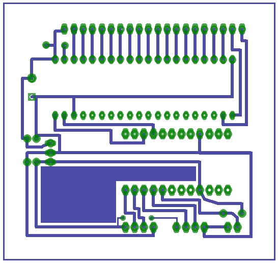
Scheme
With the help of the notorious environment for the design of Eagle CAD , the author’s scheme and a printed circuit board were improved. Here I added a voltage regulator to 5 V, changed the sensors from 3-pin expensive Ping to four-pin cheap HC-SR04 . In order for the staircase lighting to work only in the dark, a Soviet photoresistor FR-764 was added to the circuit (you can also use another one).
')
Sketch
The sketch uses a freely distributed library for working with the LED driver M5450 , as well as a library for working with the ultrasonic range finder HC-SR04.
#include "lightuino3.h" #include "Ultrasonic.h" // #define TRIG_PIN 12 #define ECHO_PIN 13 // #define TRIG2_PIN 10 #define ECHO2_PIN 11 // Ultrasonic OurModuleUp(TRIG_PIN, ECHO_PIN); // Ultrasonic OurModuleDown(TRIG2_PIN, ECHO2_PIN); // pins 0, 1 used by Serial const unsigned char DataPin = 6; const unsigned char clockPin = 7; // const long lightSpacing = 280; // const long lightHold = 10000; // const long pingReadDelay = 50; // const float minBottomIn = 33.0f; const float minTopIn = minBottomIn; LightuinoSink sinks(clockPin, DataPin, 100, 4); boolean bClimbStarted = false; boolean bDescentStarted = false; int val; void setup() { Serial.begin(9600); pinMode(DataPin, OUTPUT); pinMode(clockPin, OUTPUT); delay(1000); sinks.set(0,0,0); } void loop() { val = analogRead(0); // if (val>=1020){ UltrasonicDownFire();// if(bClimbStarted) { bClimbStarted = false; bDescentStarted = false; climbLightSequence(); } else { // UltrasonicUpFire(); if(bDescentStarted) { bClimbStarted = false; bDescentStarted = false; descentLightSequence(); } } delay(pingReadDelay); } } // void UltrasonicUpFire() { if((OurModuleUp.Ranging(INC) < minTopIn) && (OurModuleUp.Ranging(INC) > 0)) { // Serial.println("Top sensor tripped."); bDescentStarted = true; } } // ] void UltrasonicDownFire() { if((OurModuleDown.Ranging(INC) < minTopIn) && (OurModuleDown.Ranging(INC) > 0)) { // Serial.println("Bottom sensor tripped."); bClimbStarted = true; } } void climbLightSequence(){ LedsOnDown(); } void LedsOnDown(){ // byte ledState[9]; for (int j=0;j<9;j++) { ledState[j] = B00000000; } // for (int k=1;k>=0;k--) { for (int j=8;j>=1;j--) { ledState[k] = (ledState[k] >> 1) + 128; sinks.set(ledState); delay(lightSpacing); } } // delay(lightHold); // for (int k=1;k>=0;k--) { for (int j=8;j>=1;j--) { ledState[k] = (ledState[k] >> 1); sinks.set(ledState); delay(lightSpacing); } } delay(pingReadDelay); } void descentLightSequence(){ LedsOnUp(); } void LedsOnUp(){ // byte ledState[9]; for (int j=0;j<9;j++) { ledState[j] = B00000000; } // for (int k=0;k<=1;k++) { for (int j=0;j<9;j++) { ledState[k]=(ledState[k] << 1) + 1; sinks.set(ledState); delay(lightSpacing); } } delay(lightHold); for (int k=0;k<=1;k++) { for (int j=0;j<9;j++) { ledState[k]=(ledState[k] << 1); sinks.set(ledState); delay(lightSpacing); } } delay(pingReadDelay); } A little bit about the installation
Since I have the simplest wooden staircase (without a landing board), the mounting of LED strips was carried out from the end of each step.

The cable channel runs along the entire length with the wires laid and glued to liquid nails. LED strips initially have a sticky side, they stick perfectly on the tree.

Sensors were installed at the beginning of each first step at the top and bottom of the stairs. As a fastener, I used ordinary flush-mounted backing plates.

A dead battery was thrown out of the case of the power supply unit for the alarm; our controller easily fitted into its place.

The lid is in place. Place the controller under the landing.

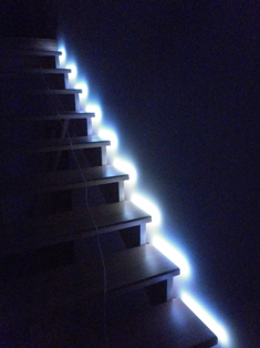
Result
In fact, the video does not reflect the real picture. The staircase is lit much more beautiful and brighter.
Download all the necessary files in one archive
UPD! Slightly finalized the scheme . Added support for PWM and high power LED strips.
Group VKontakte vk.com/ledstairs (photo, video)
Source: https://habr.com/ru/post/142685/
All Articles