The story of another electric bicycle with their own hands
Foreword
It all started last year, when I began to ride my bike more and more, because expectations in the car crowd, after the working day, the moment of arrival home began to strain more and more. The path by bike from home to work took up time almost as well as by car. But taking into account the fact that the way passed most of the roads, on which there was practically no traffic, along the coastal strip of the reservoir and the picturesque alley, in which sports-oriented people were warming up in the morning hours, and the beach was decorated with yawning fishermen with fishing rods the bike also brought moral satisfaction from admiring everything that was happening around.
(many pictures)
The only drawback that overshadowed the trips to work was a slide, about 300 meters long with a rather steep climb, at the entrance to which one had to drop to lower gears and put considerable effort. The consequence of this was not a comfortable state before the start of the working day in the office.
')
The idea was born to equip your bike with an engine that would help in difficult moments. Having studied quite a few videos on YouTube, the endless-sphere.com site forum and other resources about electrification at home of a bicycle, a picture of the solution of the problem was formed in my head. It remains only to implement.
The idea of buying a complete set with a motor-wheel on the front drive seemed banal to me simple, and also two other reasons: low developed power (up to 500 W) and high cost - did not play in her favor.
The focus was on rear-wheel drive and the use of a brushless motor. The efficiency of such a solution, it seemed, should be higher than the use of a front-wheel motor-wheel.
Already having a little experience in radio model, I decided to use the components from HobbyKing as the main ones in the construction of an electric bike to implement my ideas. The mechanics, it was decided to use the one that is easy to get in any car or bike shop.
Components
The following components were used to build an electric bike:
Hobbyking
Engine (1500 rub.)
Motor controller (700 rub.)
Rechargeable battery (1300 rub.)
Servo tester (200 rub.)
Charger (700 rub.)
Power wires (red / black) (200 rubles)
Connectors 1 , connectors 2 (200 rubles)
Wattmeter (optional) (600 rubles)
Heat shrink (optional)
Auto shop
Pulley generator VAZ-2108, 4 pcs. (500 rub.)
Alternator belt VAZ-2108, 2 pcs. (200 rubles)
Bicycle shop
Frivil (150 rub.)
Sleeve, 2 pcs. (500 rub.)
Chain (150 rub.)
Gear selector (300 rubles)
Star 52T (300 rubles)
Hardware store
Diamond disc 150 mm (150 rubles)
Screws, nuts, washers (150 rub.)
Aluminum profile 20x10 (100 rub.)
Total 7300 rubles.
Manufacturing (mechanics)
Since I was planning to build an electric bicycle with rear wheel drive, I decided to use a chain transmission to transmit torque to the rear wheel, and to increase the gear ratio I would put a star with a large number of teeth.
Initially, I planned to cut a star with the right number of teeth using laser cutting in some workshop, but the search for the finished 3D template of the desired configuration took a lot of time and did not lead to anything worthwhile. The order of cutting along with the manufacture of the template by the designer turned out to be a pretty penny (about 1,500 rubles). This put to nothing the basic principle of the conceived idea - minimizing the cost of custom-made and the use of affordable ready-made low-cost components.

Therefore, the biggest 52T star taken from the cassette was purchased at the bicycle shop (bicycle workshop). And for fixing it to the rear wheel hub in the hardware store, a diamond disk was purchased for a Bulgarian of a suitable diameter (15 cm). The central hole of the disc had to be wasted with a drill and a file to the desired diameter of the rear wheel hub. Fastening this design to the rear wheel is made with three bolts to the spokes. It is advisable to use “eared” nuts, which cling well to the spokes, as well as auto-tightening nuts (with an insert). The star should be balanced on a spinning wheel so that there are no beats in different directions.


To prevent the transmission of torque to the engine from a rotating wheel, I used a frivil with 16 teeth, which is easy to buy at any bicycle shop. The problem is that it is designed for use with sturdier chains and standard narrow chains do not fit on it. To make this possible, you need to grind the freeway teeth a little on the sides. I used for this hand-boring machine with a nozzle of a grinding stone. 10 minutes and everything is ready - it would take a long time with a file.
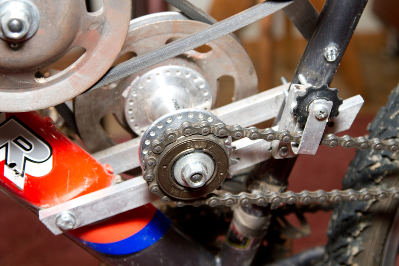
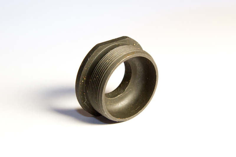
Since the frivil is designed to be wound onto the rear thick bushing, it has an internal thread of a large diameter and an adapter is needed to attach it to the transfer sleeve (with a 10 mm thread diameter). I could also find such an adapter in the bike shop. It was sold with a black sleeve and I do not know what it is for. The photo shows the second same adapter, which was on the other side with reverse thread.
For tensioning the chain from the freewheel to the driven rear wheel star, I used the standard inexpensive gearshift. The tensioner configuration turned out, of course, not the most successful, but in general it performs its role, but I could not think of anything better.


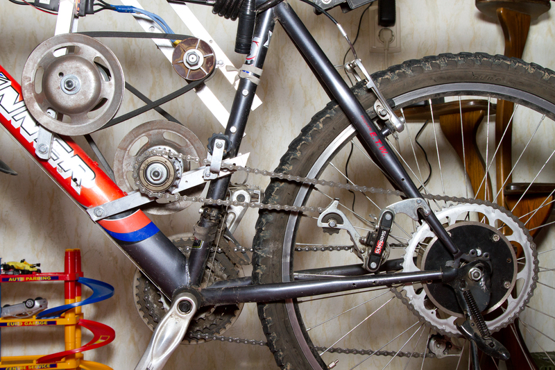
For a phased transfer of torque from the engine to the frivil, I used two adapter sleeves with pulleys mounted on them for the VAZ-2108 V-belt. The whole structure is mounted with aluminum profiles on the frame of the bike.
UPD. The frame should not be made of composite materials such as carbon, because it must be monolithic and without damage to maintain strength. Otherwise, the frame may burst. The use of aluminum frames is not recommended. It is best to use both my steel frame.

Transitional bushings are also not normal. They have a much larger diameter planes, which are attached to the spokes. This allowed them to be attached to aluminum profiles. To do this, the holes for the knitting needles are drilled a little under the M3 screws.

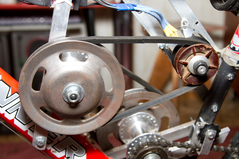
The belt pulleys have a larger inner diameter than the diameter of the thread of the adapter sleeve, therefore, to avoid inaccurate installation of the pulleys, I wrap the tape around the sleeve threads layer by layer up to the diameter of the pulley hole, and to fix the nuts I used washers with a diameter of 30 mm.
In principle, it is possible to use one transmission link of the V-belt transmission. The stock of engine power is enough for driving along straight roads and small slopes. But for a confident ride on the sand and in the hills it is better to use two links. Each link has a multiplicity of about 2x. Thereby increasing by 2 times the torque transmitted to the wheel.
Manufacturing (electrical, electronics)
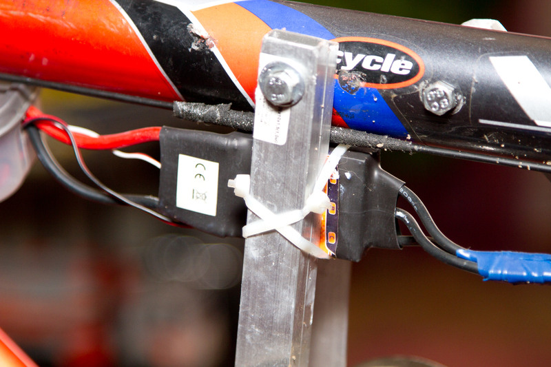
I attached the motor controller by means of cable ties to one of the aluminum profiles attached to the frame, using thermal paste for better contact. This allows you to better remove heat from the controller and in the process of driving it feels like the profile and frame in the vicinity of the controller are heated. On the other side of the controller, where its radiator is installed, I neatly cut the heat shrink with a knife and attached a small fan from the old Intel 586 processor. Although, according to operating experience, it was not necessary.

To control the power of the engine, I used a servo tester, translated into manual control mode. For powering the servo tester and cooling fan, the L7805 chip (KREN5A) is used.

At first, I soldered the variable resistor from the servo tester and placed it next to the right-hand grip on the steering wheel. It turned out that this method of smooth power adjustment has its drawbacks. It is especially inconvenient to use it in extreme situations, when you have to brake sharply, when the hand moves to the brake lever, and the engine continues to give out torque to the braking or even locked wheel.
Therefore, I simplified the scheme and made a miniature reed button “gas to the floor” (without fixing) under the thumb of my right hand, when pressed, the engine starts to give out maximum power. To eliminate sharp jerks, I put a voltage divider on two resistors and a 100 μF capacitor at the input of the servo tester. Thus, it provided a smooth increase and decrease in engine speed when pressing and releasing the “gas to the floor” button in about 0.5 - 0.7 seconds.

I put a wattmeter on the steering wheel to monitor the battery voltage and measure the “consumption” of the capacity stored in the battery. The battery is located in the seatpost zippered bag. Thus, he killed two birds with one stone - the battery is easily removed for recharging and during operation it is located in a closed safety casing, in case of an abnormal failure.
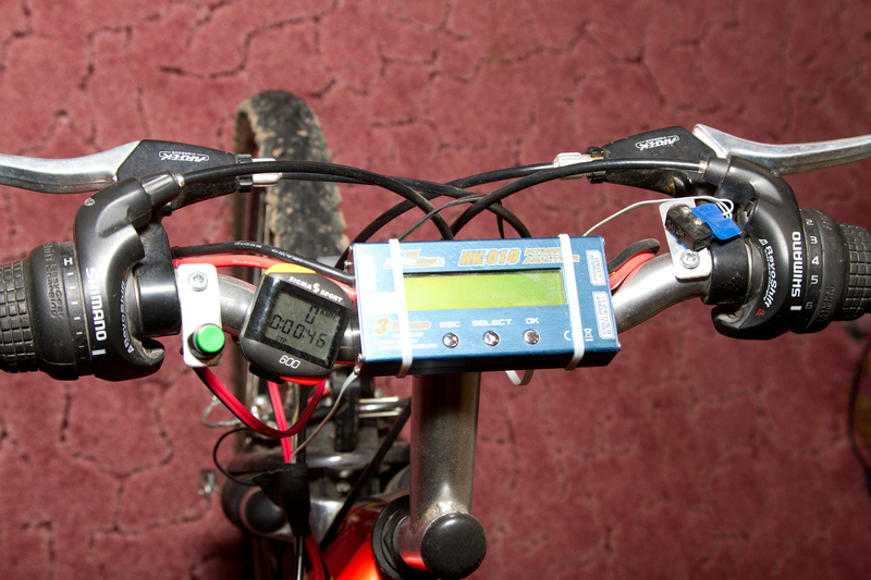

On the left grip on the steering wheel, put the reed button (without latching) for the pedestrian scare alarm. As a signal, I used a piezocrystalline car siren - a whistler. It feels quite normal during short-term operation at a voltage of 22 V (6s battery). Only louder than 12 V.
Results
I will describe several advantages and disadvantages of the applied solutions. In order.
The chain drive to the rear wheel has a fairly long run, which leads to a chain of frivil when driving on a bumpy road. To avoid this, it was necessary to fence some kind of chain guide in front of the freeway from a piece of aluminum strip and a plastic roller. As the chain beats on it, it creates an unpleasant loud knocking sound. For good it is necessary to put a tensioner or a damper chain in front of the freewheel, but has not yet figured out how.
Mount the rear driven star to the wheel is not the most reliable. There is a chance of damage to the spokes or jumping off of the star attachment. This has already happened once when I used regular nuts. After that, I put the “eared nuts” and auto checkers. It is better to change the current sleeve to the sleeve with the mounting for the disc brake and put a big star in its place. But since the diameter of the star is much larger than the disc brake, I'm not sure that the distance to the frame is enough for free rotation.
The wedge force transmission from the engine to the free wheel at first worked quite reasonably. However, the efficiency of such a solution leaves much to be desired. With increasing belt tension increases the load on the bearings of the transitional sleeves and the engine, which leads to increased wear and friction forces, and hence lower transmission efficiency. With a decrease in tension, belts under high loads (starting from a place, moving uphill) begin to slip, and this also leads to a decrease in efficiency. Finding a balance is extremely difficult. The use of multi-ribbed pulleys is problematic due to their bulkiness. The best solution seems to use a toothed belt drive.
Engine power control as in the first version using a variable resistor, as I already wrote, is often inconvenient. Using the “gas to the floor” button is often unjustified, because there are times when you need to go slowly and smoothly. The “gas to floor - acceleration - coasting on neutral” movement pattern, at least in terms of the capacity of the battery, is practically comparable to the movement with constant engine operation, and has an important drawback - V-belt slip during acceleration. But in the “gas to the floor” mode you feel all the power installed under your seat.
Well and, not fundamentally, but still, the sound of a running engine and a moving chain with an open structure often scares passersby. If one of the modellers knows how the brushless engines are whistling, he will understand.
Some interesting facts
Based on the diameters of the wedge pulleys (150 mm and 80 mm) and the number of frivil teeth and stars on the rear wheel (16 and 52), we find that the total gear ratio is 11.4. This is not very much and is not enough for a quick ride up the hill, you have to help with your feet. Therefore, I put a ceramic pulley from a washing machine (bought at a flea market) with a diameter of 64 mm on the engine. This allowed to increase the gear ratio to 14.3. With a battery voltage of 22.2 V, the maximum theoretical speed will be 45 km / h. Taking into account air resistance and power losses in transmission units, it seems to be true, because in a straight line, I accelerated to 40 km / h.
The battery capacity of 5000 mAh (22 V) is enough for 30 minutes and 8-10 km of journey at an average speed of 18 km / h and accelerations of up to 40 km / h. Even earlier, when I had a 2200 mAh battery (11 V), I also had enough of it for 8 km, but at a maximum speed of 18 km / h, an average of 14 km / h and help the engine by pedaling when moving uphill.
The maximum current consumed by the engine during acceleration in the “gas to the floor” mode is about 60 A. Thus, the power output is about 1250 W, which is several times higher than that of most motor-wheels sold. Acceleration to 40 km / h in a straight line not more than 10 seconds.
In the current configuration, I left last season from July to October to work almost every day with a daily mileage of about 20 km.
(I apologize for the dirt on some photos :)
UPD. Added a warning about the risk of reworking the frame is not steel.
Source: https://habr.com/ru/post/142598/
All Articles