Simulator for software testing
Good afternoon, dear habrozhiteli!

I'll tell you about my project, which I have been doing in my free time for three years.
')
I work in a company engaged in automation as a programmer for controllers. Lately, we mainly use Siemens, SIMATIC S7 PLC and WinCC visualization package, but there is experience from other manufacturers. The company profile is the oil and gas sector (tank farms, pumping stations, railway racks, mooring complexes, fire extinguishing systems).
Probably from the very first project, I was interested in the question of software testing up to the commissioning stage on real hardware. Not so long ago, the post was on Habré - Programming Siemens PLC on Simatic Step7 , and the adrenaline, which was mentioned in the comments, is familiar to me firsthand.
At the moment, using my software platform, we can get rid of most of the errors and debug automated functions in comfortable office conditions (rather than sitting on a cable reel, in an unheated room, on a frosty winter day).
In simplified form, our process control system consists of the following components:
From the sensors and actuators, the signals go to the PLC, are processed and transmitted to the visualization system with which the human operator interacts. Operator commands are transmitted back to the PLC, which generates the necessary signals to control the actuators. Automated functions and emergency protection (ESD) are implemented in the PLC.
We usually have two people involved in the development. One writes a program for the PLC, the second makes a visualization system. Now we are trying to use the third one - the tester. I can not say that we implement very complex control algorithms, but there is a specificity associated primarily with the size of the system. For example, my current project has a total of about 2300 signals, most of which are input (about 1500).
For testing, a stand consisting of a PLC and a visualization system is assembled in the office. Some manufacturers offer software simulators PLC, so that, sometimes, you can do with conventional computer equipment. For example, S7PLCSim from Siemens: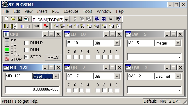
The question remains with sensors and actuators that are connected to our system via discrete / analogue input / output signals.
Some PLC manufacturers provide tools for software simulation of input signals. For example, through the Step7 programming environment of Siemens controllers, the value of any input signal can be set in a real PLC, force forced, and if you use a controller simulator, simply install via a graphical interface. In the above illustration: IB 10 is the input byte, IW 5 is the input word, QB 7 and QW 2 are the output, and MD 123 is a double word in the controller's internal memory.
Another approach that needs to be mentioned is the imitation of input signals at the iron level. For us, this approach is inconvenient - too much time is spent on connection. In addition, in the office, usually, there is only a processor module from the PLC, and modules for connecting input / output signals, which are placed in separate cabinets, are in stock or have already been sent for installation to the customer.
It is clear that by such means, it is possible to conduct a simple check of the passage of signals from the controller to the visualization system and back. You can debug not very complex automatic algorithms, the benefit is that there are breakpoints in Step7. But if several pieces of equipment are involved in the algorithm (several pumps + strapping of valves and sensors), this is quite difficult.

For several years now, for each of my projects, in addition to the PLC program, I create a software simulator of the object to be automated. English-language sources sometimes refer to such systems as the Factory Acceptance Test (FAT) simulator (simulator for factory acceptance) and classify them according to the degree of reliability of the simulation. There is not a lot of information on the creation of such simulators on the network, Matlab + Simulink, LabView are mainly used, someone implements a simulation inside the PLC. There are special development tools - WinMOD, Mynah MiMiC, Siemens SIMIT, APROS.
After some reflection, I decided to try to create my own platform. First of all, there was a desire to learn something new (.NET and #). The circumstances were successful, and our company, for one of the projects, acquired a ready OPC client library. This allowed me to concentrate on the main task.
To create a software simulator for a stand with a real PLC, it is necessary to provide in it a substitution of data obtained from physical inputs to imitation. Unfortunately, this has to be done in the controller program itself. The next step is to provide access to this data through the OPC interface. After that, you can start writing a PLC program and creating a simulator of the object to be automated.
If you use S7PLCSim - in the substitution of data is not necessary. In this case, the visualization system will have to be run on the same machine together with S7PLCSim and the object simulator (S7PLCSim restriction). In case of power shortage, you can try to post them using the free utility NetToPLCSim.
The platform that I developed is similar to the primitive environment for creating visualization systems. The work can be divided into three stages:
The simulator configuration is saved as an XML file with a simple structure:
This allows you to edit it manually, generate scripts, for example in Excel, as well as fully utilize the version control system.
So the simulator interface may look like:

Creating a simulator of an object to be automated offers many advantages:
Since this is my first experience of creating something serious in C #, first of all, I would like to rework the architecture:

On the automation.ucoz.com website you can download ademo version. It is not limited in time, but in it you can create only 20 variables and 10 simulation objects (all types except C # scripts). full version (freeware).
I'll tell you about my project, which I have been doing in my free time for three years.
')
I work in a company engaged in automation as a programmer for controllers. Lately, we mainly use Siemens, SIMATIC S7 PLC and WinCC visualization package, but there is experience from other manufacturers. The company profile is the oil and gas sector (tank farms, pumping stations, railway racks, mooring complexes, fire extinguishing systems).
Probably from the very first project, I was interested in the question of software testing up to the commissioning stage on real hardware. Not so long ago, the post was on Habré - Programming Siemens PLC on Simatic Step7 , and the adrenaline, which was mentioned in the comments, is familiar to me firsthand.
At the moment, using my software platform, we can get rid of most of the errors and debug automated functions in comfortable office conditions (rather than sitting on a cable reel, in an unheated room, on a frosty winter day).
Introduction
In simplified form, our process control system consists of the following components:
- Sensors (pressure, temperature) and actuators (valves, pumps).
- Programmable logic controller (PLC).
- Visualization system (SCADA, HMI).
From the sensors and actuators, the signals go to the PLC, are processed and transmitted to the visualization system with which the human operator interacts. Operator commands are transmitted back to the PLC, which generates the necessary signals to control the actuators. Automated functions and emergency protection (ESD) are implemented in the PLC.
We usually have two people involved in the development. One writes a program for the PLC, the second makes a visualization system. Now we are trying to use the third one - the tester. I can not say that we implement very complex control algorithms, but there is a specificity associated primarily with the size of the system. For example, my current project has a total of about 2300 signals, most of which are input (about 1500).
For testing, a stand consisting of a PLC and a visualization system is assembled in the office. Some manufacturers offer software simulators PLC, so that, sometimes, you can do with conventional computer equipment. For example, S7PLCSim from Siemens:
The question remains with sensors and actuators that are connected to our system via discrete / analogue input / output signals.
Some PLC manufacturers provide tools for software simulation of input signals. For example, through the Step7 programming environment of Siemens controllers, the value of any input signal can be set in a real PLC, force forced, and if you use a controller simulator, simply install via a graphical interface. In the above illustration: IB 10 is the input byte, IW 5 is the input word, QB 7 and QW 2 are the output, and MD 123 is a double word in the controller's internal memory.
Another approach that needs to be mentioned is the imitation of input signals at the iron level. For us, this approach is inconvenient - too much time is spent on connection. In addition, in the office, usually, there is only a processor module from the PLC, and modules for connecting input / output signals, which are placed in separate cabinets, are in stock or have already been sent for installation to the customer.
It is clear that by such means, it is possible to conduct a simple check of the passage of signals from the controller to the visualization system and back. You can debug not very complex automatic algorithms, the benefit is that there are breakpoints in Step7. But if several pieces of equipment are involved in the algorithm (several pumps + strapping of valves and sensors), this is quite difficult.
Idea
For several years now, for each of my projects, in addition to the PLC program, I create a software simulator of the object to be automated. English-language sources sometimes refer to such systems as the Factory Acceptance Test (FAT) simulator (simulator for factory acceptance) and classify them according to the degree of reliability of the simulation. There is not a lot of information on the creation of such simulators on the network, Matlab + Simulink, LabView are mainly used, someone implements a simulation inside the PLC. There are special development tools - WinMOD, Mynah MiMiC, Siemens SIMIT, APROS.
After some reflection, I decided to try to create my own platform. First of all, there was a desire to learn something new (.NET and #). The circumstances were successful, and our company, for one of the projects, acquired a ready OPC client library. This allowed me to concentrate on the main task.
To create a software simulator for a stand with a real PLC, it is necessary to provide in it a substitution of data obtained from physical inputs to imitation. Unfortunately, this has to be done in the controller program itself. The next step is to provide access to this data through the OPC interface. After that, you can start writing a PLC program and creating a simulator of the object to be automated.
If you use S7PLCSim - in the substitution of data is not necessary. In this case, the visualization system will have to be run on the same machine together with S7PLCSim and the object simulator (S7PLCSim restriction). In case of power shortage, you can try to post them using the free utility NetToPLCSim.
Platform
The platform that I developed is similar to the primitive environment for creating visualization systems. The work can be divided into three stages:
- Creating variables (Item). There are only three types:
- Internal is an internal variable that is used for communication between objects inside the simulator.
- OPC is a variable associated with an external OPC server. In this case, the simulator is an OPC client.
- S7PLCSim - this variable is intended for communication with the SIMATIC S7 controller simulator. Memory areas I, Q, M and DB are supported.
You can add and delete variables while the simulator is running. The system will not allow to delete a variable that is used. - Creating simulation objects. Currently, 13 types of objects are implemented. Among them are quite primitive ones - discrete and analog sensors, and quite complex ones - an analog signal generator and a gate valve. One of the object types allows you to write scripts in C #. By configuring each simulation object, the user sets the variables (Item) that the given object will read or write, as well as its other parameters.
Objects can be added, deleted and edited by its properties while the simulator is running. - Creating a user interface. As a base tabbed panel is used (TabControl). On each created screen you can place the display of simulation objects. For example, an analog sensor, you can display it as a slider, a field for entering a value or a graph, anywhere on the panel. The same object can be displayed any number of times, on one or several panels, in different forms.
In order to delete a simulation object, you must first delete all its displays on all panels.
The simulator configuration is saved as an XML file with a simple structure:
 <ProcessSimulator>
     <Items>
          [Variables]
     </ Items>
     <SimulationObjects>
          [Simulation Objects]
     </ SimulationObjects>
     <Screens>
          [Panels with simulated objects]
     </ Screens>
 </ ProcessSimulator>
This allows you to edit it manually, generate scripts, for example in Excel, as well as fully utilize the version control system.
So the simulator interface may look like:
Opportunities
Creating a simulator of an object to be automated offers many advantages:
- Ease of development and testing. By creating a program for a PLC and, in parallel with it, an object simulator, I can check every part of the code and simulate almost any situation. The developer of the visualization system also uses all the conveniences of the simulator, without delving into the PLC program (and without pulling me, every time when he wants to check something). A more or less normal graphical user interface allows you to bring a person to the test, who did not participate in its creation, and therefore, will find more errors than any of the creators. In addition, even at the facility, you can switch the system into simulation mode, modify something and check it completely using the software method, without using real equipment.
- Demonstration of the program part of the system, regardless of the degree of readiness of the rest.
- Operator training. The operation of the system in simulation mode allows the operator to study the operation of the system in more detail, and most importantly, without stress, (and find errors).
- Simplify warranty support system. If you recreate the conditions of an error, sometimes you can do without a trip to the object.
Further development
Since this is my first experience of creating something serious in C #, first of all, I would like to rework the architecture:
- Select the layer responsible for external connections and implement them as plug-ins. This will allow you to connect to multiple OPC servers and Siemens SIMATIC S7PLCSim instances. It will also make it easier to add other types of connections, such as Modbus.
- Implement a class of visual elements not related to simulation objects. At the moment, any user interface element on the screen is necessarily associated with the object of simulation, which is not very convenient. Sometimes there really is not enough opportunity to draw something, insert a picture or just write an explanatory text.
- Create a plug-in system for simulation objects and their mappings. The main direction of development of the platform is the expansion of the library of simulation objects, so the convenience of their creation and integration is a key factor.
Site
On the automation.ucoz.com website you can download a
Source: https://habr.com/ru/post/142596/
All Articles