Simple robot with ultrasonic range finder
This topic is dedicated to the creation of a simple robot based on the Arduino nano. It is assumed that the reader is a novice and has only a basic knowledge of this issue. I tried to explain everything in a more detailed and understandable way.
Let's start with the concept: we want a robot that can independently move around the room, while going around all the obstacles encountered in its path.
Task set. Now run shopping! 1) Platform. There are such options: do everything yourself, buy Circuits (for example Tamiya) and assemble one of them, or buy ready-made ones. I stopped at the last version. I somehow liked the type of tank, well, or tractor, and in the end I stopped at this option (platform from DF robot ):

Included - a platform (one motor on each track) and a battery compartment.
Well, it's nothing complicated, let's go further.
')
Sonar (he is a range finder, he is an Ultrasonic module). As a range finder, the choice was originally between ultrasound and infrared. Since the characteristics of the ultrasound are much better (the maximum range is about 4-5 meters, against 30-60 cm), and the price is about the same, the choice fell on the Ultrasonic. The most common model is HC-SR04 .

To understand how this fruit works - there is a datasheet + enough information on the Internet.
I'll tell you the main thing. The photo shows 2 cylinder. One is a receiver, another is a transmitter. The receiver generates ultrasonic waves, the transmitter receives the reflected wave from the object, and inform us about it. There are 4 pins on its board (5V, GND, Trig, Echo) .
The algorithm is as follows:
We send a signal of 10 μs duration to the Trig leg, which triggers the generator, which creates a packet of short pulses on the transmitter (8 pieces). Further, the receiver receives the reflected signal and a rectangular signal is generated on the Echo stem, the length of which is proportional to the time between the radiation of the pulses and their detection by the receiver.
The real time for which the sound reaches the receiver, of course, will be a penny. To determine the distance using it, you can use a simple formula:
s = vt / 2 , s is the distance, v is the speed of sound, t is the time of receiving the signal at the receiver.
Why divide in half, I think everyone understands. Only in this case, this formula is not needed. I bring it here solely for understanding the physics of the process.
From the Echo output, an already generated signal is coming, with a fairly long duration. Looking into the datasheet, we will see the recalculation formula: s = t / 58 , s is the distance, t is the pulse width Echo, s is the distance in centimeters.
Ok, like all the basics dismantled. Let's go to the code under the Arduino:
const int Trig = 3; // denote to which leg and what we connect const int Echo = 2;
void setup ()
{
pinMode (Trig, OUTPUT);
pinMode (Echo, INPUT);
Serial.begin (9600); // Initialize the serial port in order to display the result on the monitor
}
unsigned int time_us = 0; // Variable for storing the time interval
unsigned int distance_sm = 0; // Variable for storing distance in centimeters
void loop ()
{
digitalWrite (Trig, HIGH); // Send a signal to the output of the microcontroller
delayMicroseconds (10); // Hold 10 microseconds
digitalWrite (Trig, LOW); // Then remove
time_us = pulseIn (Echo, HIGH); // Measure the pulse length
distance_sm = time_us / 58; // Recalculate in centimeters
Serial.print (distance_sm); // Output to port
Serial.print ("");
delay (500);
}
Well, with a sonar it seems dealt. We continue.
The platform contains 2 motors. They need to somehow manage. It would seem - connect them directly, give it HIGH then LOW and rejoice. There is one significant “BUT” here - you will not get a current higher than ~ 40mA from an atmega, and the motor should be an order of magnitude somewhere more.
How to be? The first thing that comes to mind is to put a transistor on the output of the microcontroller and to feed the motors from it. This is certainly good, but it will not work if we want to start up the motor in the other direction ... But the H-bridge, which is a slightly more complicated circuit than a pair of transistors, will cope with this task. But in this case they are full in the form of ready-made integrated circuits, so I think there’s no need to reinvent the wheel - we’ll buy a ready-made one. In addition, the price has - 2-3 dollars ...
You can read a little about these devices, for example, here .
Let's move on. For these purposes, I bought myself an L293D microcircuit, which will be discussed later in fact. It is easy to use, universally available and has a convenient Dip16 package.
Its maximum current is relatively small (600 mA), which is more than enough for a specific task. If more is needed, that is, for example, L293B (1A), etc ...
I almost forgot, this bridge allows you to connect to it 2 motors, one on each side.
To understand how to interact with it, I found a good article , and we will use it:
Everything is simple and clear. Having carefully studied the first part of the article, let's stop the look in the figure:

- The circuit of the inclusion of this chip, in fact, taken from the datasheet.
Briefly run over her legs:
1) Initializing the motor1. Until you give this leg HIGH, whatever you do with the others, the motor will not work. Although it says 1.2E - there is only one motor. Do not confuse. The fact is that to control one motor you will need 2 legs of the microcontroller, and accordingly the H - bridge. Let's give on one leg HIGH, another LOW - the motor spun in one direction. Filed on the first LOW, the second HIGH - spin in the opposite. give both LOW - stop.
2) 1A . On this leg you will send a signal from the microcontroller (low current) to control the 1st motor input.
3) 1Y . And this is a signal (high current), which goes directly to the motor. In its appearance, it completely repeats the signal applied to input 1A .
4) - 5) Earth
6) 2Y Connect the second leg of the motor here.
7) 2A Signal from the microcontroller to control the second input of the motor.
8) Here we apply the voltage that the motors will feed on. In essence, what we give to this entrance will be unlocked on legs 1Y , 2Y .
9) - 16) Complete analogy with the first eight, but for the second motor.
Further, the inclusion scheme:


In order to remove the power surges when the motor is turned on, we use a capacitor, as shown below:

And finally, the source code is given, with my small edition, which sums up all of the above:
const int motor1Pin = 3; // H-bridge leg 1 (pin 2, 1A)
const int motor2Pin = 4; // H-bridge leg 2 (pin 7, 2A)
const int enablePin = 9; // H-bridge enable pin
void setup ()
{// set all the other pins you're using as outputs:
pinMode (motor1Pin, OUTPUT);
pinMode (motor2Pin, OUTPUT);
pinMode (enablePin, OUTPUT); // set enablePin so that motor can turn on:
digitalWrite (enablePin, HIGH);
}
void loop ()
{// Rotate the motor in one direction
digitalWrite (motor1Pin, LOW); // set leg 1 of the H-bridge low
digitalWrite (motor2Pin, HIGH); // set leg 2 of the H-bridge high delay (1000); // And in a second to another digitalWrite (motor1Pin, HIGH); // set leg 1 of the H-bridge high
digitalWrite (motor2Pin, LOW); // set leg 2 of the H-bridge low delay (1000);
// And now all over again
}
So, we have dealt with the work of the range finder. Let's move on. We have one range finder, we need to look both forward and to the sides in order to know where to turn in case of anything. For these purposes, we use the servo (servo, servo, servo).

These toys are used mainly in aircraft modeling, but for robots it is also very personal.
This device can be rotated at angles from 0 to 180 degrees. From the case there is a three-core cable:
Black - GND
Red - 5V
White - Signal
The motor is controlled by the controller (do not worry - you do not need to buy anything, it is already inside the servo), which, receiving an external signal, controls that the motor turns to a given angle. For these purposes, a feedback is sent from the motor to the controller, which is a variable resistor, changing its resistance depending on the angle of rotation. The controller itself is controlled by the length of the input pulse. As a rule: 380-400 µs - 0 degrees, 2200µs - 180 degrees. Here is a simple servo control algorithm for the Arduino:
#define ServoPin 2 // On this leg we connect our servo (its white wire)
void setup ()
{
pinMode (2, OUTPUT);
}
void Servo_motion (int angle) // servo control function
{
int time = 390 + 10 * angle; // Recalculate the specified angle of rotation in the pulse length, which we give to // servo
digitalWrite (ServoPin, HIGH); // Signal went
delayMicroseconds (time); // Hold it for a given time
digitalWrite (ServoPin, LOW); // Turn It Off
delayMicroseconds (20000-time); // Give the servo time to turn around (20,000 μs - 50 Hz)
}
void loop ()
{
for (int i = 0; i <= 180; i ++)
{
Servo_motion (i); // Scroll the servo to one side
delay (10); // With a delay of 10 milliseconds at each degree
}
for (int i = 180; i> = 0; i--)
{
Servo_motion (i); // Then the other way
delay (10);
}
}
But in the future, we will use a special library to control the servo, here is its description:
www.arduino.cc/en/Reference/Servo
arduino.cc/en/Tutorial/Sweep
This example (2 link) does absolutely the same as the program described above. There is a colorful description of the code with pictures, pictures, comments, so I think - there will not be any particular difficulties. I will confine myself to just a few comments - when checking this code, do not forget to rearrange the servo to digital port 9, or correct this line in that code:
myservo.attach (9); // attaches the servo on pin 9 to the servo object
And that will earn nothing. And the last thing I would like to add is that this example is available both through the above link and in the Arduino development environment in the Examples tab.
Let's proceed to the assembly of our creation. Since I didn’t pay, I don’t have a concept, unfortunately. But I think it will not hurt us much - the scheme is simple, everything is clear. Photos and small comments would be enough. At this stage there is Arduino nano, as you might have guessed, since all the previous code was made with the expectation of it. Describing this device is quite time-consuming and tedious, so for those who do not know - links:
arduino.cc/en/Guide/HomePage
freeduino.ru/arduino/index.html
arduino.ru
I still, as before, will assume that you have at least a small, but still an experience of acquaintance with this thing, well, or at least just imagine what it is. In this case, this is quite enough. So, having picked up not a lot of knowledge, let's eat further.
Let's start with the connections. I will list which input and what I have connected:
4 legs - entrances of the H bridge, 2 for each motor:
1A - 11
2A - 6
3A - 10
4A - 5
enablePin - 12
1 Leg under 1,2EN and 3,4EN - planted them together, since we still don’t need both motors separately. In principle, in general, you can not connect these 2 legs of the bridge to the Arduino, but simply apply 5V to them.
2 legs for sonar:
Trig - 3
Echo-2
Leg for servo connection:
Servo - 8
This seems to be all. Further, in the process of assembling the robot, I ran into one problem - the robot periodically stopped, the Arduino rebooted. A little thought, I realized that the Arduino nano is unable to power this whole system (H-bridge, servo, sonar) from its standard stabilizer. Therefore, voltage stabilizer 7805 (L7805, LM7805) came to my aid. The device is easy to use, has 3 legs: input (6 - 35 V), ground, output (~ 5V). Datashit to it can be found everywhere on the Internet. By combining his land, with the land of the Arduino and, accordingly, with the minus of the battery too. I did it - from the Arduino, I feed only H - the bridge, and everything else (servo, sonar) from the stabilizer. After that, the robot began to work perfectly without failures. Yes, do not forget the important rule - the earth in any scheme should be common to all elements! Well, about the motors themselves, I think it is clear - we apply voltage from the battery to the input of the bridge - Vcc2. Well, sort of made out the connection, illustrate the above photos:
The whole scheme:

Voltage stabilizer (capacitors can not be put):

Train from sonar:

H - bridge:
A little about the design itself: there were no frills). Cut plastic cover on the platform, it had a hole for mounting the servo. From the same plastic is bent (preheating by an industrial hairdryer) an L-shaped bracket. A four-core cable (under the PLS plug, with a 2.54mm pitch) is glued to it, into which the sonar itself is already inserted.
So, the robot is assembled. We proceed to the final stage - firmware. Here I will describe my implementation of this algorithm. I will note in advance that everything could be significantly simplified, for example, it was not constant to rotate the sonar, but to stop when there was an obstacle on the way, “look around” and turn in the best direction. Or do not rotate the head.
Well, here we will not look for easy ways, besides the first option is the most interesting and entertaining. The code presented below is of course damp, in some places it may not be optimal. So all your comments and suggestions are welcome. Nevertheless, this version has proven itself in field conditions. Well, let's get started. I will explain the main points of the code, in a sequence that is most convenient for understanding:
Variable for the implementation of the sonar algorithm - unsigned int time_us = 0;
Distance determined by sonar - unsigned int distance_sm = 0;
This variable is used in the loop to ensure that when turned on, the robot “looked around” on the spot, and then it went
unsigned int circle = 0;
The distance to the nearest object in front is unsigned int dist_f = 0;
The distance to the nearest object on the left is unsigned int dist_l = 0;
The distance to the nearest object to the right is unsigned int dist_r = 0;
The distance to the nearest object at an angle of 45 degrees - unsigned int dist_45 = 0;
Distance to the nearest object at an angle of 135 degrees - unsigned int dist_135 = 0;
Time constant (ms), which determines the minimum step of the robot movement. Selected experimentally. Depending on the speed of movement and the speed of rotation of the servo of your robot, you may have to change it. Later it will become more clear why it is needed -
unsigned int t = 15;
sonar () - implements the algorithm of the sonar operation, returns the distance [cm].
forward (), back (), right (), left () are our basic motion functions.
The main function that implements the movement -
void motion (char dimention, int prev_angle, int next_angle, int time)
{
/ * This function simultaneously controls both the rotation of the motors and the servo.
char dimention - direction of travel
int prev_angle - previous servo position
int next_angle - the position on which we want to set the servo
int time - time step of one robot movement * /
// The value by which the angle changes during movement -
int a;
if (next_angle> = prev_angle)
a = 15;
else
a = -15;
if (dimention == 'f')
{
// If it is said to move forward, then
int i = prev_angle;
while (i! = next_angle)
{
/ * Until we reach the specified angle value, we will gradually change the current position of the servo by the value of a * /
i + = a; myservo.write (i); // And transfer this value to the servo
forward (); // Then move forward
delay (time); // During the time interval
}
}
/ * A similar algorithm for moving left, right, back and standing still * /
...
}
void front_motion (int time)
{
/ * A function that performs a small “turning around” of the robot to one of the sides, if the object is located at angles of 45 and 135 degrees * /
if (dist_45 <= 9)
{// If the distance to the object at an angle of 45 degrees is less than 9 cm, turn left
left ();
delay (3 * time); // Within three minimum intervals of movement
}
/ * Similar algorithm for “turning” to the right * /
...
}
void motion_back (int time)
{
/ * Movement of the robot back during the time 2 * time, with rotation of the servo from the angle of 180 degrees, at an angle of 180 degrees * /
motion ('b', 180,90,2 * time);
}
void loop ()
{
// Our main function that implements the final work algorithm
if (circle == 0)
{
// If the robot has just been turned on, set the servo to the initial position.
myservo.write (0); // And "look around" around
dist_r = sonar ();
motion ('w', 0.45, t);
dist_45 = sonar ();
motion ('w', 45.90, t);
dist_f = sonar ();
motion ('w', 90,135, t);
dist_135 = sonar ();
motion ('w', 135,180, t);
dist_l = sonar (); } // We will not perform this action anymore.
circle ++; i
f (dist_f> = 25)
{// If more than 25 centimeters to the nearest object
a: // Moving forward, while turning the servo from 180 to 135 degrees
motion ('f', 180,135, t); // Make a measurement of the distance to objects at an angle of 135 degrees
dist_135 = sonar (); // If necessary, we will do the rotation
front_motion (t); // Next, similar, but with different values
motion ('f', 135.90, t);
dist_f = sonar ();
front_motion (t);
motion ('f', 90,45, t);
dist_45 = sonar ();
front_motion (t);
motion ('f', 45,0, t);
dist_r = sonar ();
front_motion (t);
motion ('f', 0.45, t);
dist_45 = sonar ();
front_motion (t);
motion ('f', 45.90, t);
dist_f = sonar ();
front_motion (t);
motion ('f', 90,135, t);
dist_135 = sonar ();
front_motion (t);
motion ('f', 135,180, t);
dist_l = sonar (); front_motion (t); // If the front distance is still more than 25 centimeters, then return to the 'a' point
if (dist_f> = 25)
goto a;
}
else
{ //If not
if (dist_f <5)
{// If the robot is already too close to the nearest object, then we move backward.
motion_back (t);
// Make a new distance measurement
dist_f = sonar ();
} // At the same time, we turn in the direction where there is more free space.
if (dist_l> = dist_r || dist_135> dist_r)
{
motion ('l', 180.90, t);
dist_f = sonar ();
}
if (dist_l <dist_r)
{
motion ('r', 180.90, t);
dist_f = sonar ();
}
} // Next new circle
}
The full version of this program can be downloaded here:
maxim.wf/arduino_code/Robot_compilation.pde
So, here we come to the end of this topic. The robot is completed, everything works) The path was quite long, but interesting and enjoyable. Now you have the experience of creating a robot, possessing, let oooooochen primitive, but still artificial intelligence, on the basis of which you can create more complex things. To some extent, you can even feel yourself the Creator of a certain organism, similar in mind to the simplest creatures. Here is a video with our final result:
Thanks for attention!
I will be glad to any questions, suggestions and comments.
Introduction to the problem
Let's start with the concept: we want a robot that can independently move around the room, while going around all the obstacles encountered in its path.
Task set. Now run shopping! 1) Platform. There are such options: do everything yourself, buy Circuits (for example Tamiya) and assemble one of them, or buy ready-made ones. I stopped at the last version. I somehow liked the type of tank, well, or tractor, and in the end I stopped at this option (platform from DF robot ):
Included - a platform (one motor on each track) and a battery compartment.
Well, it's nothing complicated, let's go further.
')
Rangefinder
Sonar (he is a range finder, he is an Ultrasonic module). As a range finder, the choice was originally between ultrasound and infrared. Since the characteristics of the ultrasound are much better (the maximum range is about 4-5 meters, against 30-60 cm), and the price is about the same, the choice fell on the Ultrasonic. The most common model is HC-SR04 .
To understand how this fruit works - there is a datasheet + enough information on the Internet.
I'll tell you the main thing. The photo shows 2 cylinder. One is a receiver, another is a transmitter. The receiver generates ultrasonic waves, the transmitter receives the reflected wave from the object, and inform us about it. There are 4 pins on its board (5V, GND, Trig, Echo) .
The algorithm is as follows:
We send a signal of 10 μs duration to the Trig leg, which triggers the generator, which creates a packet of short pulses on the transmitter (8 pieces). Further, the receiver receives the reflected signal and a rectangular signal is generated on the Echo stem, the length of which is proportional to the time between the radiation of the pulses and their detection by the receiver.
The real time for which the sound reaches the receiver, of course, will be a penny. To determine the distance using it, you can use a simple formula:
s = vt / 2 , s is the distance, v is the speed of sound, t is the time of receiving the signal at the receiver.
Why divide in half, I think everyone understands. Only in this case, this formula is not needed. I bring it here solely for understanding the physics of the process.
From the Echo output, an already generated signal is coming, with a fairly long duration. Looking into the datasheet, we will see the recalculation formula: s = t / 58 , s is the distance, t is the pulse width Echo, s is the distance in centimeters.
Ok, like all the basics dismantled. Let's go to the code under the Arduino:
const int Trig = 3; // denote to which leg and what we connect const int Echo = 2;
void setup ()
{
pinMode (Trig, OUTPUT);
pinMode (Echo, INPUT);
Serial.begin (9600); // Initialize the serial port in order to display the result on the monitor
}
unsigned int time_us = 0; // Variable for storing the time interval
unsigned int distance_sm = 0; // Variable for storing distance in centimeters
void loop ()
{
digitalWrite (Trig, HIGH); // Send a signal to the output of the microcontroller
delayMicroseconds (10); // Hold 10 microseconds
digitalWrite (Trig, LOW); // Then remove
time_us = pulseIn (Echo, HIGH); // Measure the pulse length
distance_sm = time_us / 58; // Recalculate in centimeters
Serial.print (distance_sm); // Output to port
Serial.print ("");
delay (500);
}
Driver
Well, with a sonar it seems dealt. We continue.
The platform contains 2 motors. They need to somehow manage. It would seem - connect them directly, give it HIGH then LOW and rejoice. There is one significant “BUT” here - you will not get a current higher than ~ 40mA from an atmega, and the motor should be an order of magnitude somewhere more.
How to be? The first thing that comes to mind is to put a transistor on the output of the microcontroller and to feed the motors from it. This is certainly good, but it will not work if we want to start up the motor in the other direction ... But the H-bridge, which is a slightly more complicated circuit than a pair of transistors, will cope with this task. But in this case they are full in the form of ready-made integrated circuits, so I think there’s no need to reinvent the wheel - we’ll buy a ready-made one. In addition, the price has - 2-3 dollars ...
You can read a little about these devices, for example, here .
Let's move on. For these purposes, I bought myself an L293D microcircuit, which will be discussed later in fact. It is easy to use, universally available and has a convenient Dip16 package.
Its maximum current is relatively small (600 mA), which is more than enough for a specific task. If more is needed, that is, for example, L293B (1A), etc ...
I almost forgot, this bridge allows you to connect to it 2 motors, one on each side.
To understand how to interact with it, I found a good article , and we will use it:
Everything is simple and clear. Having carefully studied the first part of the article, let's stop the look in the figure:
- The circuit of the inclusion of this chip, in fact, taken from the datasheet.
Briefly run over her legs:
1) Initializing the motor1. Until you give this leg HIGH, whatever you do with the others, the motor will not work. Although it says 1.2E - there is only one motor. Do not confuse. The fact is that to control one motor you will need 2 legs of the microcontroller, and accordingly the H - bridge. Let's give on one leg HIGH, another LOW - the motor spun in one direction. Filed on the first LOW, the second HIGH - spin in the opposite. give both LOW - stop.
2) 1A . On this leg you will send a signal from the microcontroller (low current) to control the 1st motor input.
3) 1Y . And this is a signal (high current), which goes directly to the motor. In its appearance, it completely repeats the signal applied to input 1A .
4) - 5) Earth
6) 2Y Connect the second leg of the motor here.
7) 2A Signal from the microcontroller to control the second input of the motor.
8) Here we apply the voltage that the motors will feed on. In essence, what we give to this entrance will be unlocked on legs 1Y , 2Y .
9) - 16) Complete analogy with the first eight, but for the second motor.
Further, the inclusion scheme:
In order to remove the power surges when the motor is turned on, we use a capacitor, as shown below:
And finally, the source code is given, with my small edition, which sums up all of the above:
const int motor1Pin = 3; // H-bridge leg 1 (pin 2, 1A)
const int motor2Pin = 4; // H-bridge leg 2 (pin 7, 2A)
const int enablePin = 9; // H-bridge enable pin
void setup ()
{// set all the other pins you're using as outputs:
pinMode (motor1Pin, OUTPUT);
pinMode (motor2Pin, OUTPUT);
pinMode (enablePin, OUTPUT); // set enablePin so that motor can turn on:
digitalWrite (enablePin, HIGH);
}
void loop ()
{// Rotate the motor in one direction
digitalWrite (motor1Pin, LOW); // set leg 1 of the H-bridge low
digitalWrite (motor2Pin, HIGH); // set leg 2 of the H-bridge high delay (1000); // And in a second to another digitalWrite (motor1Pin, HIGH); // set leg 1 of the H-bridge high
digitalWrite (motor2Pin, LOW); // set leg 2 of the H-bridge low delay (1000);
// And now all over again
}
Servo machine
So, we have dealt with the work of the range finder. Let's move on. We have one range finder, we need to look both forward and to the sides in order to know where to turn in case of anything. For these purposes, we use the servo (servo, servo, servo).
These toys are used mainly in aircraft modeling, but for robots it is also very personal.
This device can be rotated at angles from 0 to 180 degrees. From the case there is a three-core cable:
Black - GND
Red - 5V
White - Signal
The motor is controlled by the controller (do not worry - you do not need to buy anything, it is already inside the servo), which, receiving an external signal, controls that the motor turns to a given angle. For these purposes, a feedback is sent from the motor to the controller, which is a variable resistor, changing its resistance depending on the angle of rotation. The controller itself is controlled by the length of the input pulse. As a rule: 380-400 µs - 0 degrees, 2200µs - 180 degrees. Here is a simple servo control algorithm for the Arduino:
#define ServoPin 2 // On this leg we connect our servo (its white wire)
void setup ()
{
pinMode (2, OUTPUT);
}
void Servo_motion (int angle) // servo control function
{
int time = 390 + 10 * angle; // Recalculate the specified angle of rotation in the pulse length, which we give to // servo
digitalWrite (ServoPin, HIGH); // Signal went
delayMicroseconds (time); // Hold it for a given time
digitalWrite (ServoPin, LOW); // Turn It Off
delayMicroseconds (20000-time); // Give the servo time to turn around (20,000 μs - 50 Hz)
}
void loop ()
{
for (int i = 0; i <= 180; i ++)
{
Servo_motion (i); // Scroll the servo to one side
delay (10); // With a delay of 10 milliseconds at each degree
}
for (int i = 180; i> = 0; i--)
{
Servo_motion (i); // Then the other way
delay (10);
}
}
But in the future, we will use a special library to control the servo, here is its description:
www.arduino.cc/en/Reference/Servo
arduino.cc/en/Tutorial/Sweep
This example (2 link) does absolutely the same as the program described above. There is a colorful description of the code with pictures, pictures, comments, so I think - there will not be any particular difficulties. I will confine myself to just a few comments - when checking this code, do not forget to rearrange the servo to digital port 9, or correct this line in that code:
myservo.attach (9); // attaches the servo on pin 9 to the servo object
And that will earn nothing. And the last thing I would like to add is that this example is available both through the above link and in the Arduino development environment in the Examples tab.
Assembly
Let's proceed to the assembly of our creation. Since I didn’t pay, I don’t have a concept, unfortunately. But I think it will not hurt us much - the scheme is simple, everything is clear. Photos and small comments would be enough. At this stage there is Arduino nano, as you might have guessed, since all the previous code was made with the expectation of it. Describing this device is quite time-consuming and tedious, so for those who do not know - links:
arduino.cc/en/Guide/HomePage
freeduino.ru/arduino/index.html
arduino.ru
I still, as before, will assume that you have at least a small, but still an experience of acquaintance with this thing, well, or at least just imagine what it is. In this case, this is quite enough. So, having picked up not a lot of knowledge, let's eat further.
Let's start with the connections. I will list which input and what I have connected:
4 legs - entrances of the H bridge, 2 for each motor:
1A - 11
2A - 6
3A - 10
4A - 5
enablePin - 12
1 Leg under 1,2EN and 3,4EN - planted them together, since we still don’t need both motors separately. In principle, in general, you can not connect these 2 legs of the bridge to the Arduino, but simply apply 5V to them.
2 legs for sonar:
Trig - 3
Echo-2
Leg for servo connection:
Servo - 8
This seems to be all. Further, in the process of assembling the robot, I ran into one problem - the robot periodically stopped, the Arduino rebooted. A little thought, I realized that the Arduino nano is unable to power this whole system (H-bridge, servo, sonar) from its standard stabilizer. Therefore, voltage stabilizer 7805 (L7805, LM7805) came to my aid. The device is easy to use, has 3 legs: input (6 - 35 V), ground, output (~ 5V). Datashit to it can be found everywhere on the Internet. By combining his land, with the land of the Arduino and, accordingly, with the minus of the battery too. I did it - from the Arduino, I feed only H - the bridge, and everything else (servo, sonar) from the stabilizer. After that, the robot began to work perfectly without failures. Yes, do not forget the important rule - the earth in any scheme should be common to all elements! Well, about the motors themselves, I think it is clear - we apply voltage from the battery to the input of the bridge - Vcc2. Well, sort of made out the connection, illustrate the above photos:
The whole scheme:
Voltage stabilizer (capacitors can not be put):
Train from sonar:
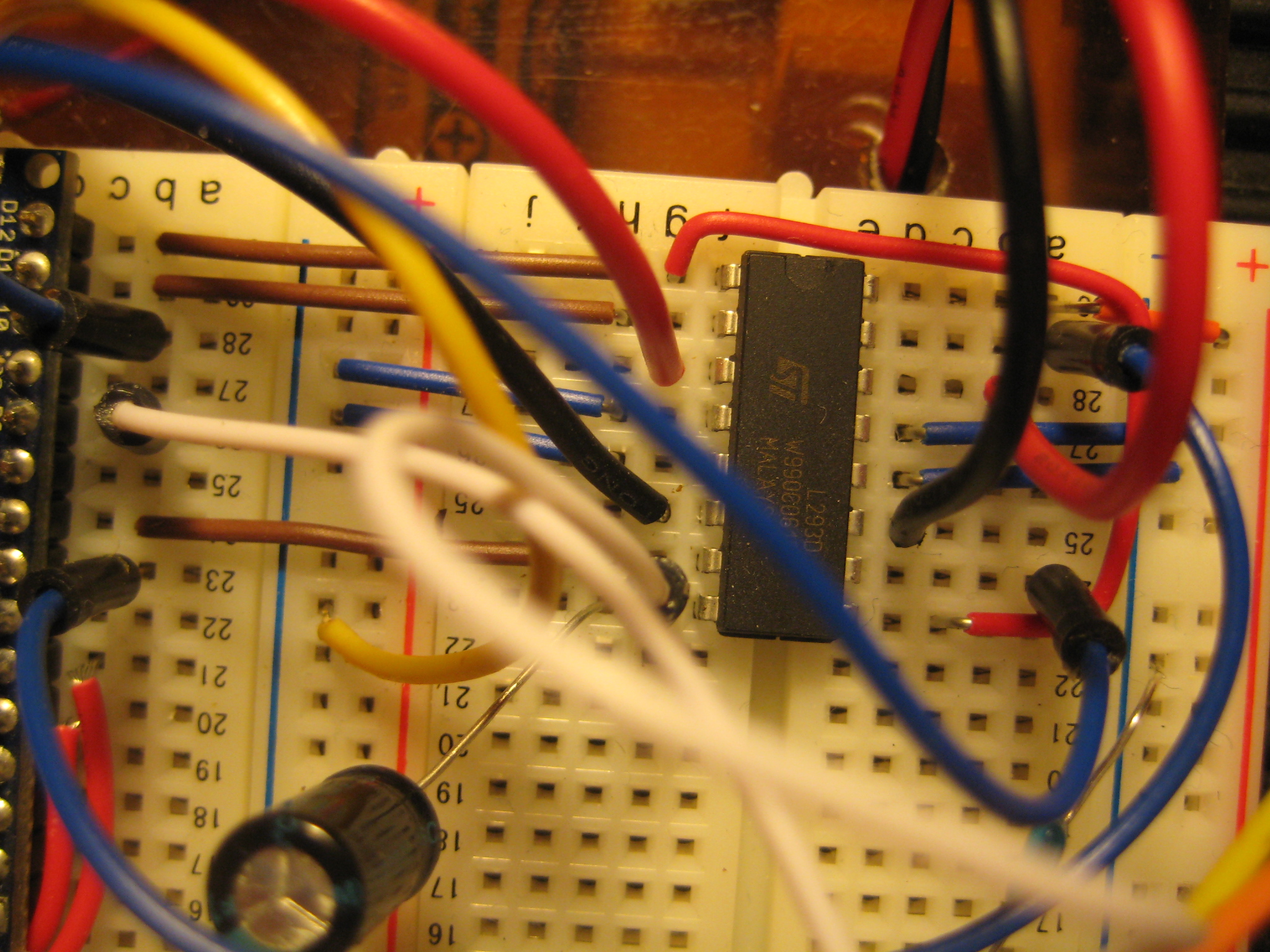
H - bridge:
A little about the design itself: there were no frills). Cut plastic cover on the platform, it had a hole for mounting the servo. From the same plastic is bent (preheating by an industrial hairdryer) an L-shaped bracket. A four-core cable (under the PLS plug, with a 2.54mm pitch) is glued to it, into which the sonar itself is already inserted.
Programming
So, the robot is assembled. We proceed to the final stage - firmware. Here I will describe my implementation of this algorithm. I will note in advance that everything could be significantly simplified, for example, it was not constant to rotate the sonar, but to stop when there was an obstacle on the way, “look around” and turn in the best direction. Or do not rotate the head.
Well, here we will not look for easy ways, besides the first option is the most interesting and entertaining. The code presented below is of course damp, in some places it may not be optimal. So all your comments and suggestions are welcome. Nevertheless, this version has proven itself in field conditions. Well, let's get started. I will explain the main points of the code, in a sequence that is most convenient for understanding:
Variable declaration:
Variable for the implementation of the sonar algorithm - unsigned int time_us = 0;
Distance determined by sonar - unsigned int distance_sm = 0;
This variable is used in the loop to ensure that when turned on, the robot “looked around” on the spot, and then it went
unsigned int circle = 0;
The distance to the nearest object in front is unsigned int dist_f = 0;
The distance to the nearest object on the left is unsigned int dist_l = 0;
The distance to the nearest object to the right is unsigned int dist_r = 0;
The distance to the nearest object at an angle of 45 degrees - unsigned int dist_45 = 0;
Distance to the nearest object at an angle of 135 degrees - unsigned int dist_135 = 0;
Time constant (ms), which determines the minimum step of the robot movement. Selected experimentally. Depending on the speed of movement and the speed of rotation of the servo of your robot, you may have to change it. Later it will become more clear why it is needed -
unsigned int t = 15;
Functions:
sonar () - implements the algorithm of the sonar operation, returns the distance [cm].
forward (), back (), right (), left () are our basic motion functions.
The main function that implements the movement -
void motion (char dimention, int prev_angle, int next_angle, int time)
{
/ * This function simultaneously controls both the rotation of the motors and the servo.
char dimention - direction of travel
int prev_angle - previous servo position
int next_angle - the position on which we want to set the servo
int time - time step of one robot movement * /
// The value by which the angle changes during movement -
int a;
if (next_angle> = prev_angle)
a = 15;
else
a = -15;
if (dimention == 'f')
{
// If it is said to move forward, then
int i = prev_angle;
while (i! = next_angle)
{
/ * Until we reach the specified angle value, we will gradually change the current position of the servo by the value of a * /
i + = a; myservo.write (i); // And transfer this value to the servo
forward (); // Then move forward
delay (time); // During the time interval
}
}
/ * A similar algorithm for moving left, right, back and standing still * /
...
}
void front_motion (int time)
{
/ * A function that performs a small “turning around” of the robot to one of the sides, if the object is located at angles of 45 and 135 degrees * /
if (dist_45 <= 9)
{// If the distance to the object at an angle of 45 degrees is less than 9 cm, turn left
left ();
delay (3 * time); // Within three minimum intervals of movement
}
/ * Similar algorithm for “turning” to the right * /
...
}
void motion_back (int time)
{
/ * Movement of the robot back during the time 2 * time, with rotation of the servo from the angle of 180 degrees, at an angle of 180 degrees * /
motion ('b', 180,90,2 * time);
}
void loop ()
{
// Our main function that implements the final work algorithm
if (circle == 0)
{
// If the robot has just been turned on, set the servo to the initial position.
myservo.write (0); // And "look around" around
dist_r = sonar ();
motion ('w', 0.45, t);
dist_45 = sonar ();
motion ('w', 45.90, t);
dist_f = sonar ();
motion ('w', 90,135, t);
dist_135 = sonar ();
motion ('w', 135,180, t);
dist_l = sonar (); } // We will not perform this action anymore.
circle ++; i
f (dist_f> = 25)
{// If more than 25 centimeters to the nearest object
a: // Moving forward, while turning the servo from 180 to 135 degrees
motion ('f', 180,135, t); // Make a measurement of the distance to objects at an angle of 135 degrees
dist_135 = sonar (); // If necessary, we will do the rotation
front_motion (t); // Next, similar, but with different values
motion ('f', 135.90, t);
dist_f = sonar ();
front_motion (t);
motion ('f', 90,45, t);
dist_45 = sonar ();
front_motion (t);
motion ('f', 45,0, t);
dist_r = sonar ();
front_motion (t);
motion ('f', 0.45, t);
dist_45 = sonar ();
front_motion (t);
motion ('f', 45.90, t);
dist_f = sonar ();
front_motion (t);
motion ('f', 90,135, t);
dist_135 = sonar ();
front_motion (t);
motion ('f', 135,180, t);
dist_l = sonar (); front_motion (t); // If the front distance is still more than 25 centimeters, then return to the 'a' point
if (dist_f> = 25)
goto a;
}
else
{ //If not
if (dist_f <5)
{// If the robot is already too close to the nearest object, then we move backward.
motion_back (t);
// Make a new distance measurement
dist_f = sonar ();
} // At the same time, we turn in the direction where there is more free space.
if (dist_l> = dist_r || dist_135> dist_r)
{
motion ('l', 180.90, t);
dist_f = sonar ();
}
if (dist_l <dist_r)
{
motion ('r', 180.90, t);
dist_f = sonar ();
}
} // Next new circle
}
The full version of this program can be downloaded here:
maxim.wf/arduino_code/Robot_compilation.pde
So, here we come to the end of this topic. The robot is completed, everything works) The path was quite long, but interesting and enjoyable. Now you have the experience of creating a robot, possessing, let oooooochen primitive, but still artificial intelligence, on the basis of which you can create more complex things. To some extent, you can even feel yourself the Creator of a certain organism, similar in mind to the simplest creatures. Here is a video with our final result:
Thanks for attention!
I will be glad to any questions, suggestions and comments.
Source: https://habr.com/ru/post/142156/
All Articles