We connect headphones to the TV
Briefly about where the task was born. My father is well over 70. He is in excellent physical shape, runs the laboratory, does not get out of the Internet, but he doesn’t hear very well. Moreover, there is one peculiarity: because of uneven changes in the sensitivity of hearing at different frequencies (the specialist had them), even the very loud TV, the father hears poorly, but he hears them on the headphones at the same volume level that suits me.
So, the task: to connect the headphones to the TV, of course there is no jack on the TV. Solvable? Of course! Who is relevant and / or interesting - I ask under the cat.
The first thing that comes to mind is to open the TV, cut the headphone jack on the wall and connect it to the TV speaker circuit. But then a good question arises: the action when you turn on the headphone jack.
If you turn off the TV speakers when you turn on the headphones, then only the father with headphones can watch TV, or only someone without them, plus at the same time constantly poking the headphones into the socket will quickly lead to bad things.
If the TV speakers do not turn off when turning on the headphones, the idea loses its meaning - it’s unrealistic to choose an equally comfortable sound level for those who listen in headphones and for those who listen in speakers.
The idea with a nest sidebar was rejected. Another was born.
The TV has a SCART connector (by the way, it is on most TVs).

On SCART there is an audio output - this is a linear output, the TV volume control does not affect it.
So, the idea is simple: organize independent sound output on the headphones.
The first thing I tried was to make a radio extension: a small (1 transistor) transmitter in the FM band, well, and listen to it on a regular FM receiver. Schemes of this kind on the Internet are a dime a dozen, there is nothing military there, but as it turned out, there is a big problem: within a few hours of listening, the frequency goes away, you have to constantly tune the receiver.
By referring to abnormal electronics, quartz was added to the circuit to stabilize the frequency, another problem came out - because of the quartz, the frequency deviation (if you are interested in what I am talking about - please ) turned out to be small and the sound is very quiet.
The idea of a radio extension was rejected.
')
The simplest idea was implemented - SCART-> small amplifier-> long cord-> headphones with volume control.
Headphones with volume control - not uncommon, were chosen Sven.
Extension cord - three-core thick wire, positioned by the sellers as a microphone. The wire in the screen, but the screen is not needed here and is not connected. Why is fat - because it is not so confused, he has to constantly move.
Amplifier.
On the radio market, ready-made welded scarves are sold, costing around $ 3, there are quite a few options. Principle - like a cat, four legs (conditional of course): entrance, exit, ground and food. There are stereo options (then “legs,” respectively, six).
In particular, there is no need to go into the circuit; this is a standard power amplifier on a microcircuit according to a typical switching circuit. The only thing you should pay attention to is that the microcircuit should be designed to work without a radiator.
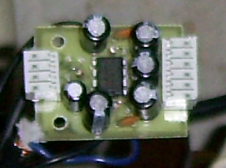
I chose a handkerchief on a TDA2822 microcircuit - this is a stereo amplifier with a power up to 1 W.
If the TV had USB, you could take the power of the amplifier from there. But no USB, I had to look for a power supply.
Usually all such small amplifiers are not critical to power, from + 5V to + 12V work without problems, stabilization or additional smoothing is not required. You can use the power supply from an old mobile phone, from the "Polish" antenna, etc. I got the old power supply from the Dendy prefix - 9 volts, inside - only a diode bridge and a condenser. He went to work.
The main thing when connecting the power supply is not to confuse the polarity, it is better to double-check the tester. If you confuse + and -, with a very high probability kirdyk amplifier will come instantly.
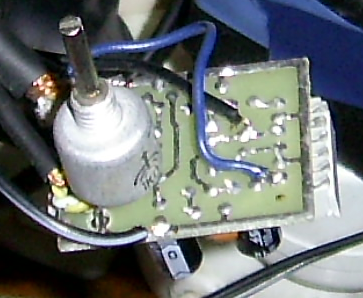
There is a feature of connecting such an amplifier to a TV. The first power-up showed that the sound was wheezing, and this was not treated with the headphone volume control - the signal from the TV was too strong, needed to be reduced, and the variable resistor was roughly fused to the handkerchief from the tracks. Its resistance in the range from 1 to 10 kΩ, is not very critical, I used what I turned up and what was convenient to solder to the board - 1 kΩ.
It looks like this:
The final scheme turned out like this:

From the scheme it is immediately clear that this is mono. We do not broadcast on cable stereo, there is no need to bother, but there is no problem to make stereo, only a second resistor is needed to adjust the level of the second channel, or a dual resistor.
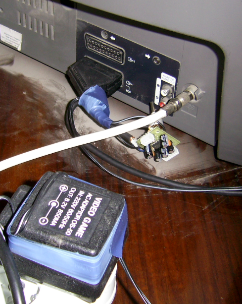
Completely all design connected to TV:
After the assembly and connection, a small adjustment is required: we twist the resistor on the board so that it is louder, but wheezing does not appear at the volume peaks yet. Check on several TV channels.
PS I understand well that this is in fact the “g # inode” in electronics: on the knee, quickly, it works and is hidden from prying eyes. But the result is achieved:
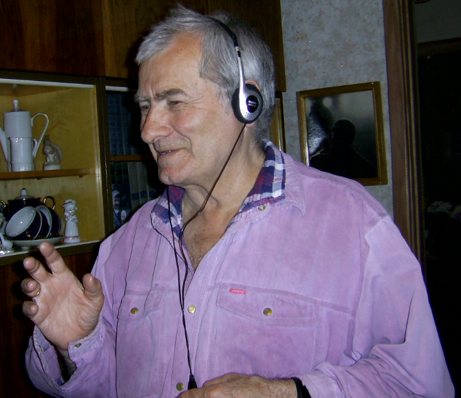
The father adjusts the volume on his headset; everyone else who watches TV regulates the volume with the remote on the TV — everyone is good.
So, the task: to connect the headphones to the TV, of course there is no jack on the TV. Solvable? Of course! Who is relevant and / or interesting - I ask under the cat.
The first thing that comes to mind is to open the TV, cut the headphone jack on the wall and connect it to the TV speaker circuit. But then a good question arises: the action when you turn on the headphone jack.
If you turn off the TV speakers when you turn on the headphones, then only the father with headphones can watch TV, or only someone without them, plus at the same time constantly poking the headphones into the socket will quickly lead to bad things.
If the TV speakers do not turn off when turning on the headphones, the idea loses its meaning - it’s unrealistic to choose an equally comfortable sound level for those who listen in headphones and for those who listen in speakers.
The idea with a nest sidebar was rejected. Another was born.
The TV has a SCART connector (by the way, it is on most TVs).
On SCART there is an audio output - this is a linear output, the TV volume control does not affect it.
So, the idea is simple: organize independent sound output on the headphones.
The first thing I tried was to make a radio extension: a small (1 transistor) transmitter in the FM band, well, and listen to it on a regular FM receiver. Schemes of this kind on the Internet are a dime a dozen, there is nothing military there, but as it turned out, there is a big problem: within a few hours of listening, the frequency goes away, you have to constantly tune the receiver.
By referring to abnormal electronics, quartz was added to the circuit to stabilize the frequency, another problem came out - because of the quartz, the frequency deviation (if you are interested in what I am talking about - please ) turned out to be small and the sound is very quiet.
The idea of a radio extension was rejected.
')
The simplest idea was implemented - SCART-> small amplifier-> long cord-> headphones with volume control.
Headphones with volume control - not uncommon, were chosen Sven.
Extension cord - three-core thick wire, positioned by the sellers as a microphone. The wire in the screen, but the screen is not needed here and is not connected. Why is fat - because it is not so confused, he has to constantly move.
Amplifier.
On the radio market, ready-made welded scarves are sold, costing around $ 3, there are quite a few options. Principle - like a cat, four legs (conditional of course): entrance, exit, ground and food. There are stereo options (then “legs,” respectively, six).
In particular, there is no need to go into the circuit; this is a standard power amplifier on a microcircuit according to a typical switching circuit. The only thing you should pay attention to is that the microcircuit should be designed to work without a radiator.
I chose a handkerchief on a TDA2822 microcircuit - this is a stereo amplifier with a power up to 1 W.
If the TV had USB, you could take the power of the amplifier from there. But no USB, I had to look for a power supply.
Usually all such small amplifiers are not critical to power, from + 5V to + 12V work without problems, stabilization or additional smoothing is not required. You can use the power supply from an old mobile phone, from the "Polish" antenna, etc. I got the old power supply from the Dendy prefix - 9 volts, inside - only a diode bridge and a condenser. He went to work.
The main thing when connecting the power supply is not to confuse the polarity, it is better to double-check the tester. If you confuse + and -, with a very high probability kirdyk amplifier will come instantly.
There is a feature of connecting such an amplifier to a TV. The first power-up showed that the sound was wheezing, and this was not treated with the headphone volume control - the signal from the TV was too strong, needed to be reduced, and the variable resistor was roughly fused to the handkerchief from the tracks. Its resistance in the range from 1 to 10 kΩ, is not very critical, I used what I turned up and what was convenient to solder to the board - 1 kΩ.
It looks like this:
The final scheme turned out like this:
From the scheme it is immediately clear that this is mono. We do not broadcast on cable stereo, there is no need to bother, but there is no problem to make stereo, only a second resistor is needed to adjust the level of the second channel, or a dual resistor.
Completely all design connected to TV:
After the assembly and connection, a small adjustment is required: we twist the resistor on the board so that it is louder, but wheezing does not appear at the volume peaks yet. Check on several TV channels.
PS I understand well that this is in fact the “g # inode” in electronics: on the knee, quickly, it works and is hidden from prying eyes. But the result is achieved:
The father adjusts the volume on his headset; everyone else who watches TV regulates the volume with the remote on the TV — everyone is good.
Source: https://habr.com/ru/post/142085/
All Articles