RepRap: a bit of practice, theory and how to avoid mistakes during assembly (part 1)
About 3D printers have already written a cart and a small cart, but when you start collecting on your own, you come across a bunch of questions and problems that are not described anywhere ...
This post is a small guide for beginners RepRapers (well, and the rest is useful) about bumps that I stuffed when assembling my RepRap Prusa Mendel.
Printers class RepRap - print, mostly plastic bar. This does not mean that they are limited only to them: there are modifications for chocolate, tin, the attachment of the cutter, etc.
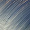
But the main thing - a plastic bar.
The seal boils down to the fact that we feed this very bar with an extruder into the heating head, where it melts and is pressed under the pressure of the bar being pushed into the head through the nozzle. The resulting trickle of plastic we shake along the XY coordinates, sticking first to the table, and then to the previous layer.
There are several subtleties:
1. If plastic sticks to itself perfectly, then it is problematic to the table. Therefore, the table is heated and covered with “Kapton” - amber-colored thermoscaps. FZ is why it is, but experiments show that it sticks to it best.
2. The method does not allow printing overhanging parts. The bar simply does not have time to freeze in the air and sags ... Solutions are, of course, but it is necessary to take into account.
')
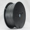
So, there are two main players in the plastic market for printers: ABS and PLA.
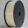
Acrylonitrile butadiene styrene, or just ABS. “A shock-resistant technical thermoplastic resin based on a copolymer of acrylonitrile with butadiene and styrene (the name of the plastic is formed from the initial letters of the names of monomers)”.
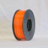
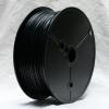
Usually - yellowish-milky color, but can be colored due to dyes.
The problem is that if in our country the white ABS has been established more or less to produce, then with a color one, they have some kind of stupid crap ...
Pros: cheap (about 600 rubles per kilogram, plus or minus), dissolves in acetone (you can smooth out the "steps" of printing).
Cons: need a heated table and Kapton. Children are better not to give.
The working temperature is around 210 degrees. Plus or minus kilometer: it can work at 180, it can also not melt at 230 ... It is selected experimentally for a purchased bar lot.
Desktop - about 110 degrees and Kapton.
As a piece of advice, pre-spread the table with a solution of plastic on acetone: it will stick so that the figs are removed!
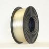
Polylactic (PLA) is a biodegradable, biocompatible, thermoplastic, aliphatic polyether, the monomer of which is lactic acid. The raw materials for production are annually renewable resources such as corn and sugar cane.
Pros: PLA parts have good sliding, of which bearings can be made. Well, it is not toxic and can be given to children.
Cons: dear, brute! Twice as expensive as ABS! And since decomposes in two years - it is better not to use for long-playing things!
As an additional plus - it has enough smooth surface for the desktop, without heating and Kapton!
As an additional minus - acetone does not take it almost ...
The working temperature is about 185 degrees.
Svezhachek - on sale appeared literally the other day.
Infa is small, only what is soluble in water is known. It is used as a separator for printing composite parts, when, for example, a nut is printed, which is immediately attached to the bolt: after printing, the separator is washed out and the nut quietly turns on the bolt!
Pros: soluble in water, which is useful in some things.
Cons: soluble in water, which is harmful in completely different situations. And dear, brute! More expensive than PLA!
They print most often with ABS: it is cheaper and more reliable ... The rest are for the situation: for example, the people are puzzled to print linear bearings for printers from PLA.
About all kinds of optical, etc. I will not say - there is a completely different principle.
Here we will talk about the "prutkovye" printers, which have already accumulated a lot of models and in which people are slowly beginning to swim.

In the beginning was the word and the word was Darwin.
Perhaps there were some other prototypes, but he was the first RepRap.
In Darwin, the printhead moved along the XY axes at the top of the "cube", and the platform went down on four heels as it went along the edges connected to the motor with toothed belts.
Later RepRap printers practically left this practice: only Darwin’s “illegitimate son” inherited it - Maker Bot Thing-o-matic.
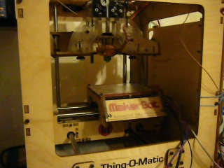
Avoiding the concept of "self-coping" printers. Maker Bots are almost 90% made of laser-cut plywood. For the rest, they are quite close in concept with Darwin: the descending platform and the head moves along the XY.
It is said that this arrangement gives MakerBots and their clones greater printing accuracy. Perhaps - I will not argue.
But as a minus - to print on MakerBot the details to MakerBoth for a friend you will not work!

T.N. "Original" or "Classic."
As it is not funny, but Darwin's concept did not take root among the RepRaps: Mendel became “triangular”, the desktop began to travel only on the Y-axis, and the print head - on X and Z. And the Z axis served only one motor with a belt drive for a couple studs ...
It is said that the original Mendel was terribly complicated to set up and assemble.
Therefore, now the main player is his descendant from the Czech Republic:
Someone may be indignant with such a transcription, but the fact is that this is not English, this is Czech. The author of the modification is Czech Joseph Pryusha.
According to many, Pruša-Mendel is simpler to assemble.
In principle - it is very similar to the original Mendel, but ...
One of the main things - Joseph abandoned the belt transmission on the studs for the Z-axis and put two motors directly connected to the corresponding studs.
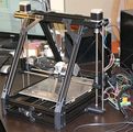
If Darwin, Mendel and Pryusha are assembled on the basis of M8 studs, then Mendel Max is from a figure profile.
In theory, it gives a greater rigidity of the structure, but if the stud is sold for 36 rubles per square meter in the same stroymarket, then the desired profile must also be found somewhere !!!
To some extent, the authors try to rest on the fact that “But we can print this profile on the printer itself!”
In practice - well, obviously, the size of the printed area will not give room for the profile of the desired length!

Printers of the type "Orcs" - an attempt to replace part of the parts with "factory" ones with laser cutting, etc. Pure RepRap are not; it doesn’t print details for it ...

The crown of simplicity in the assembly: a minimum of parts, a minimum of "unprinted" parts and in general.
There are plywood versions of this printer from the authors, but ...
One of the main advantages - it varies in size and due to the lack of a frame - is very compact!
In the minimal configuration, the printer has the following items:
Well, and others, such as the second extruder, which also need a heater and thermistor, limit switches in the "maximum", a fan for cooling the head, etc.
Clearly, all this is simply not possible to connect to a computer, so the “intermediate link” in the form of a controller is used.
The “problem” is that you can’t just put a model drawn in a 3D studio into a controller: it’s not enough for him to have such a 3D brain - the maximum that it can do is to turn the motors and catch information from the sensors. What did they want from AVR?
Therefore, the so-called G-code to control milling, etc. CNC machine tools.
Actually G-code is a set of simple commands in the style “Move on XY on ... at speed ...”, “Set temperature ... on ...”, “Move on ... until the end switch”, etc.
A special program on a computer - Slicer is engaged in converting models into G-code. To her, we will return.
G-code on sites usually do not lay out, because He often sharpened for a specific printer.
Tip: if the part is going to be repeated later - save the G-code! Conversion is a rather long process!
In the future, the control program slowly bits the G-code to the controller and it executes it.
Or, in some modifications of the controller, a card reader for the Micro-SD is installed and the program pours the G-code onto the entire card, after which the computer can even be turned off: in such cases, an LCD display and several buttons are usually connected to the controller for control and monitoring.
Go through the components:
Many beginners believe that this is the name of a particular model.
So: it is not so! This is the standard for the "seat" step!
The specific model is entirely dependent on the collector!
Brief "educational program" about stepping engines:
If a simple motor works on the principle of “energized and turned round”, then the shagoviki have several windings and when the current is applied to one of them the motor is fixed in a certain position. They filed for the next one and turned it off on this one - he took a step forward. Switched to the previous - a step back.
Control wires, usually four. Current is fed to the next pair of wires, then to “this + next”, etc.
This is the so-called. "Step" or "full-step" mode.
Most shagovik - 200 steps. Those. he must take 200 steps to rotate the rotor 360 degrees.
Is it a lot or a little?
A complete revolution — for the Z axis, is the movement per millimeter.
200 steps - divide it into sections of 0.005 mm.
It seems not bad, but you always want MORE!
Therefore, the people came up with a “half-step” mode: the current is fed not to two, but to three adjacent wires, i.e. - on a pair of neighboring windings at the same time! At the same time, the engine freezes between two steps.
Then one of the windings is turned off and it goes to it, then the next one turns on when this one is working - it moves half a step forward ... And so on.
How not difficult to count - 400 steps!
But ... “We want more!” The people screamed and came up with the “Micro-stepping” mode!
In the stepper - we turn on the individual windings, in the semi-stepper - we apply equal voltage to the neighboring voltages ...
And what will happen if one winding is applied two times less? And three?
Praavavilno! The rotor will not stop in the middle between the two windings, but “with zakos” towards the greater !!!
Thus, the step is divided into 4, 8 and 16 parts (it is possible and more, but I will honestly say - I did not see it above the “sixteenth”!) !!!
It didn’t really matter, but if the engine “clicks” in the transition between steps, then the step division makes it more silent! On the divider “16” the printer works in such a way that it cannot be heard from the next room with the doors open !!!
The problem is that if there are four “bridges” for the stepping and semi-stepping modes, the “microstep” is more complicated.
Therefore, some firms have established the release of "stepper motor controllers."
The logic of the motor controller is simple to ugliness: we supply power for the logical part and for the engine, after which a direction and a “step” signal are sent to a pair of control contacts: there is a “step” —the motor is supplied with voltage to move the rotor to a step, half-step or micro-step, depending on what we set jumpers.
Scheme, if anyone is interested.
The controllers of the footsteps recently come in usually with the 1/16 mode, but you can run into 1/8: bought here on Ebay, did not look, but turned out to be the "eight" ...
"Big-eyed" notice that there is a variable resistor on the controller.
What for?
And to adjust the operating voltage of the walkers: they, alas, are also under 12 volts, and under 4 and under 8, etc.
How to setup?
We expose the regulator to about the middle. (if in doubt, you can unscrew to the extreme left position (counterclockwise))
After connecting the motors (on the assembled printer!), Turn on ONE of them and give the command to move from the program.
If you pull - well.
If it pulls up and after stopping, we twist the regulator counterclockwise until it stops.
If you do not pull - we twist clockwise.
Again we start the movement and repeat as necessary.
We need a balance between "not buzzing" and "normally goes"!
After setting up one engine, we give a command to turn off the motors and repeat with the next one!
We need to determine the zero, that would stop the engines before they are a thread smash.
There are optical and pressure.
Optical - optocoupler, getting into the slot where the "flag" of the trailer sends a signal to the controller.
Push button - stupid button. Mikrik ...
The stump is clear - optical more precisely. But for XY accuracy is not particularly needed, so you can save it ...
A thermistor is needed to measure the temperature of the printhead and the heating table.
The principle is simple: its resistance varies with temperature ...
Total - we measure the resistance and get the temperature!
Simply?
Oh well…
There are two problems:
1. Working temperature range up to 300 degrees. We do not really need that much, but below - only 200 degrees! I was so stuck up, as a result, at 220 degrees my thermistor "fell asleep" ...
2. Calibration table: thermistors are not everywhere and not particularly linear dependencies ... Therefore, the people of them KAK-TO calibrates and spreads the table ...
Total: a thermistor is better to take one of those for which there are dependency tables !
Comment:
Wires to thermistors should be the minimum possible length !!!
Remember that we measure RESISTANCE in the conductor and long wires are extra Ohms in the chain !!!
“Traditionally” people usually used nichrome wire for these purposes.
But it is rather a chore to wind it up, measure it, etc. Yes, it is even stressful to buy something !!!
Therefore, people for these purposes began to use resistors of certain types ...
The point is that some resistors, in fact, the same nichrome wire, only in the case! Well, as a result - they warm up when energizing that your iron ...
Comment:
Remember that the working temperature for plastic - about 200 degrees and above!
Solder usually melts at 100 degrees!
And what happens?
Praaaavilno - your wires go to hell grandmother !!!
Use crimping garbage to connect the wires and the contacts of the heater: connector terminals, etc.
As an option, of course, high-temperature solders, but this is a rather dreary process ...
Some use nichrome wire glued to an aluminum sheet from below, others glue a stack of resistors that are in the heater ...
And still others - went along the path of least resistance, counted the very resistance, and in the editor they drew a board with a long curved path on the foiled Getinax, which corresponds in properties to nichrome wire!
Total - pretty "penny" and a beautiful solution!
Tip:
Do not glue kapton tape directly on the thermal board!
The fact is that the tape sometimes needs to be changed, and to glue it neatly in the printer is DIFFICULT!
Yes, and sometimes it is necessary to remove the part along with the base, so that it would tear off quietly ...
Therefore, we cut a rectangle in the form of a thermo-table from the foiled Getinax, glue a thermoscatch on it and attach it to the table with metal stationery pins !!!
Need to take out? Unhooked clothespins and removed! Profit!
With electronic parts of the printer almost everything.
The only thing that can be said before going to the controller:
Tip:
Buy Thermal Glue "Radial" !!!
This is crap, like a processor thermal paste, but it PASTES !!!
It is better to glue the thermistors to them, to them, to glue the heater in. Well, I also use it as insulation for the wires at the heater ...
So,
In general, lately printer controllers have made the IDE compatible with the Arduino, under which almost all firmware have been written.
The main players are RAMPS, Sanguinololu, and various versions of Generation Electronics.
Here it should be noted that the numbers in Gen are not versions, but different approaches.
Gen 3 - controller board and motor controllers are spaced apart, wired. If you want a mess on the table - your choice.
Gen 6 - motor controllers (chips) are soldered to the control board tightly. Burn one - fix the entire board, because There SMD installation of these microcircuits.
Gen 7 - Pololu motor controllers in the "beds". Plus, powered by ATX power supply and assembly without SMD components. ATmega644 as a processor.
The combination of Sanguino (Arduino clone) and Pololu (motor controllers).
In principle - a close relative of Gen 7, but more compact installation.
As a minus - Gen7 is designed for “laser-ironing” boards, and here you won’t scatter ...
RepRap Arduino Mega Pololu Shield - as the name implies - is a “shell” between Arduino and Pololu motor controllers. "My choice".
What are the buns:
Cons: you have to pay for Arduin, sheld and motor controllers. Well, a bunch of SMD editing, which is not all fun ...
So far - I like it the most, but, they say, several competitors have appeared ...
Part 1 came to an end.
In the second part you will learn:
What is Slicer and what for?
Look at the details under the "skirt" and suggest "bridges".
What is an extruder, how it works and what the print head is.
Well, and so on, remember what in the process!
This post is a small guide for beginners RepRapers (well, and the rest is useful) about bumps that I stuffed when assembling my RepRap Prusa Mendel.
Part 0, or what and how to print
Printers class RepRap - print, mostly plastic bar. This does not mean that they are limited only to them: there are modifications for chocolate, tin, the attachment of the cutter, etc.
But the main thing - a plastic bar.
The seal boils down to the fact that we feed this very bar with an extruder into the heating head, where it melts and is pressed under the pressure of the bar being pushed into the head through the nozzle. The resulting trickle of plastic we shake along the XY coordinates, sticking first to the table, and then to the previous layer.
There are several subtleties:
1. If plastic sticks to itself perfectly, then it is problematic to the table. Therefore, the table is heated and covered with “Kapton” - amber-colored thermoscaps. FZ is why it is, but experiments show that it sticks to it best.
2. The method does not allow printing overhanging parts. The bar simply does not have time to freeze in the air and sags ... Solutions are, of course, but it is necessary to take into account.
')
So, there are two main players in the plastic market for printers: ABS and PLA.
ABS
Acrylonitrile butadiene styrene, or just ABS. “A shock-resistant technical thermoplastic resin based on a copolymer of acrylonitrile with butadiene and styrene (the name of the plastic is formed from the initial letters of the names of monomers)”.
Usually - yellowish-milky color, but can be colored due to dyes.
The problem is that if in our country the white ABS has been established more or less to produce, then with a color one, they have some kind of stupid crap ...
Pros: cheap (about 600 rubles per kilogram, plus or minus), dissolves in acetone (you can smooth out the "steps" of printing).
Cons: need a heated table and Kapton. Children are better not to give.
The working temperature is around 210 degrees. Plus or minus kilometer: it can work at 180, it can also not melt at 230 ... It is selected experimentally for a purchased bar lot.
Desktop - about 110 degrees and Kapton.
As a piece of advice, pre-spread the table with a solution of plastic on acetone: it will stick so that the figs are removed!
PLA
Polylactic (PLA) is a biodegradable, biocompatible, thermoplastic, aliphatic polyether, the monomer of which is lactic acid. The raw materials for production are annually renewable resources such as corn and sugar cane.
Pros: PLA parts have good sliding, of which bearings can be made. Well, it is not toxic and can be given to children.
Cons: dear, brute! Twice as expensive as ABS! And since decomposes in two years - it is better not to use for long-playing things!
As an additional plus - it has enough smooth surface for the desktop, without heating and Kapton!
As an additional minus - acetone does not take it almost ...
The working temperature is about 185 degrees.
"Dark Horse" - PVA
Svezhachek - on sale appeared literally the other day.
Infa is small, only what is soluble in water is known. It is used as a separator for printing composite parts, when, for example, a nut is printed, which is immediately attached to the bolt: after printing, the separator is washed out and the nut quietly turns on the bolt!
Pros: soluble in water, which is useful in some things.
Cons: soluble in water, which is harmful in completely different situations. And dear, brute! More expensive than PLA!
Summary:
They print most often with ABS: it is cheaper and more reliable ... The rest are for the situation: for example, the people are puzzled to print linear bearings for printers from PLA.
Chapter 1. The Difference Between Different Printer Models
About all kinds of optical, etc. I will not say - there is a completely different principle.
Here we will talk about the "prutkovye" printers, which have already accumulated a lot of models and in which people are slowly beginning to swim.
Darwin
In the beginning was the word and the word was Darwin.
Perhaps there were some other prototypes, but he was the first RepRap.
In Darwin, the printhead moved along the XY axes at the top of the "cube", and the platform went down on four heels as it went along the edges connected to the motor with toothed belts.
Later RepRap printers practically left this practice: only Darwin’s “illegitimate son” inherited it - Maker Bot Thing-o-matic.
Maker Bot Thing-o-matic
Avoiding the concept of "self-coping" printers. Maker Bots are almost 90% made of laser-cut plywood. For the rest, they are quite close in concept with Darwin: the descending platform and the head moves along the XY.
It is said that this arrangement gives MakerBots and their clones greater printing accuracy. Perhaps - I will not argue.
But as a minus - to print on MakerBot the details to MakerBoth for a friend you will not work!
Mendel
T.N. "Original" or "Classic."
As it is not funny, but Darwin's concept did not take root among the RepRaps: Mendel became “triangular”, the desktop began to travel only on the Y-axis, and the print head - on X and Z. And the Z axis served only one motor with a belt drive for a couple studs ...
It is said that the original Mendel was terribly complicated to set up and assemble.
Therefore, now the main player is his descendant from the Czech Republic:
Mendel Pryusha (Prusa)
Someone may be indignant with such a transcription, but the fact is that this is not English, this is Czech. The author of the modification is Czech Joseph Pryusha.
According to many, Pruša-Mendel is simpler to assemble.
In principle - it is very similar to the original Mendel, but ...
One of the main things - Joseph abandoned the belt transmission on the studs for the Z-axis and put two motors directly connected to the corresponding studs.
Mendel Max
If Darwin, Mendel and Pryusha are assembled on the basis of M8 studs, then Mendel Max is from a figure profile.
In theory, it gives a greater rigidity of the structure, but if the stud is sold for 36 rubles per square meter in the same stroymarket, then the desired profile must also be found somewhere !!!
To some extent, the authors try to rest on the fact that “But we can print this profile on the printer itself!”
In practice - well, obviously, the size of the printed area will not give room for the profile of the desired length!
Orca
Printers of the type "Orcs" - an attempt to replace part of the parts with "factory" ones with laser cutting, etc. Pure RepRap are not; it doesn’t print details for it ...
Printrbot
The crown of simplicity in the assembly: a minimum of parts, a minimum of "unprinted" parts and in general.
There are plywood versions of this printer from the authors, but ...
One of the main advantages - it varies in size and due to the lack of a frame - is very compact!
Chapter 2. How and what to steer.
In the minimal configuration, the printer has the following items:
- 4 (5) stepper motors - XY-Z + extruder
- Temperature sensors for nozzle and heating table
- Table and Head Heaters
- Three end sensors on axes at zero
Well, and others, such as the second extruder, which also need a heater and thermistor, limit switches in the "maximum", a fan for cooling the head, etc.
Clearly, all this is simply not possible to connect to a computer, so the “intermediate link” in the form of a controller is used.
The “problem” is that you can’t just put a model drawn in a 3D studio into a controller: it’s not enough for him to have such a 3D brain - the maximum that it can do is to turn the motors and catch information from the sensors. What did they want from AVR?
Therefore, the so-called G-code to control milling, etc. CNC machine tools.
Actually G-code is a set of simple commands in the style “Move on XY on ... at speed ...”, “Set temperature ... on ...”, “Move on ... until the end switch”, etc.
A special program on a computer - Slicer is engaged in converting models into G-code. To her, we will return.
G-code on sites usually do not lay out, because He often sharpened for a specific printer.
Tip: if the part is going to be repeated later - save the G-code! Conversion is a rather long process!
In the future, the control program slowly bits the G-code to the controller and it executes it.
Or, in some modifications of the controller, a card reader for the Micro-SD is installed and the program pours the G-code onto the entire card, after which the computer can even be turned off: in such cases, an LCD display and several buttons are usually connected to the controller for control and monitoring.
Go through the components:
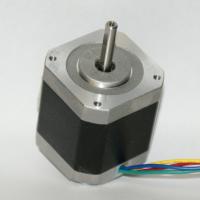
NEMA-17 stepper motors
Many beginners believe that this is the name of a particular model.
So: it is not so! This is the standard for the "seat" step!
The specific model is entirely dependent on the collector!
Brief "educational program" about stepping engines:
If a simple motor works on the principle of “energized and turned round”, then the shagoviki have several windings and when the current is applied to one of them the motor is fixed in a certain position. They filed for the next one and turned it off on this one - he took a step forward. Switched to the previous - a step back.
Control wires, usually four. Current is fed to the next pair of wires, then to “this + next”, etc.
This is the so-called. "Step" or "full-step" mode.
Most shagovik - 200 steps. Those. he must take 200 steps to rotate the rotor 360 degrees.
Is it a lot or a little?
A complete revolution — for the Z axis, is the movement per millimeter.
200 steps - divide it into sections of 0.005 mm.
It seems not bad, but you always want MORE!
Therefore, the people came up with a “half-step” mode: the current is fed not to two, but to three adjacent wires, i.e. - on a pair of neighboring windings at the same time! At the same time, the engine freezes between two steps.
Then one of the windings is turned off and it goes to it, then the next one turns on when this one is working - it moves half a step forward ... And so on.
How not difficult to count - 400 steps!
But ... “We want more!” The people screamed and came up with the “Micro-stepping” mode!
In the stepper - we turn on the individual windings, in the semi-stepper - we apply equal voltage to the neighboring voltages ...
And what will happen if one winding is applied two times less? And three?
Praavavilno! The rotor will not stop in the middle between the two windings, but “with zakos” towards the greater !!!
Thus, the step is divided into 4, 8 and 16 parts (it is possible and more, but I will honestly say - I did not see it above the “sixteenth”!) !!!
It didn’t really matter, but if the engine “clicks” in the transition between steps, then the step division makes it more silent! On the divider “16” the printer works in such a way that it cannot be heard from the next room with the doors open !!!
The problem is that if there are four “bridges” for the stepping and semi-stepping modes, the “microstep” is more complicated.
Therefore, some firms have established the release of "stepper motor controllers."
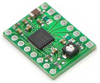
Stepper Motor Controller
The logic of the motor controller is simple to ugliness: we supply power for the logical part and for the engine, after which a direction and a “step” signal are sent to a pair of control contacts: there is a “step” —the motor is supplied with voltage to move the rotor to a step, half-step or micro-step, depending on what we set jumpers.
Scheme, if anyone is interested.
The controllers of the footsteps recently come in usually with the 1/16 mode, but you can run into 1/8: bought here on Ebay, did not look, but turned out to be the "eight" ...
"Big-eyed" notice that there is a variable resistor on the controller.
What for?
And to adjust the operating voltage of the walkers: they, alas, are also under 12 volts, and under 4 and under 8, etc.
How to setup?
We expose the regulator to about the middle. (if in doubt, you can unscrew to the extreme left position (counterclockwise))
After connecting the motors (on the assembled printer!), Turn on ONE of them and give the command to move from the program.
If you pull - well.
If it pulls up and after stopping, we twist the regulator counterclockwise until it stops.
If you do not pull - we twist clockwise.
Again we start the movement and repeat as necessary.
We need a balance between "not buzzing" and "normally goes"!
After setting up one engine, we give a command to turn off the motors and repeat with the next one!
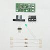
Terminal Sensors
We need to determine the zero, that would stop the engines before they are a thread smash.
There are optical and pressure.
Optical - optocoupler, getting into the slot where the "flag" of the trailer sends a signal to the controller.
Push button - stupid button. Mikrik ...
The stump is clear - optical more precisely. But for XY accuracy is not particularly needed, so you can save it ...
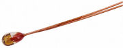
Thermistors
A thermistor is needed to measure the temperature of the printhead and the heating table.
The principle is simple: its resistance varies with temperature ...
Total - we measure the resistance and get the temperature!
Simply?
Oh well…
There are two problems:
1. Working temperature range up to 300 degrees. We do not really need that much, but below - only 200 degrees! I was so stuck up, as a result, at 220 degrees my thermistor "fell asleep" ...
2. Calibration table: thermistors are not everywhere and not particularly linear dependencies ... Therefore, the people of them KAK-TO calibrates and spreads the table ...
Total: a thermistor is better to take one of those for which there are dependency tables !
Comment:
Wires to thermistors should be the minimum possible length !!!
Remember that we measure RESISTANCE in the conductor and long wires are extra Ohms in the chain !!!
Extruder heater
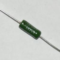
“Traditionally” people usually used nichrome wire for these purposes.
But it is rather a chore to wind it up, measure it, etc. Yes, it is even stressful to buy something !!!
Therefore, people for these purposes began to use resistors of certain types ...
The point is that some resistors, in fact, the same nichrome wire, only in the case! Well, as a result - they warm up when energizing that your iron ...
Comment:
Remember that the working temperature for plastic - about 200 degrees and above!
Solder usually melts at 100 degrees!
And what happens?
Praaaavilno - your wires go to hell grandmother !!!
Use crimping garbage to connect the wires and the contacts of the heater: connector terminals, etc.
As an option, of course, high-temperature solders, but this is a rather dreary process ...
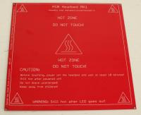
Desktop heater
Some use nichrome wire glued to an aluminum sheet from below, others glue a stack of resistors that are in the heater ...
And still others - went along the path of least resistance, counted the very resistance, and in the editor they drew a board with a long curved path on the foiled Getinax, which corresponds in properties to nichrome wire!
Total - pretty "penny" and a beautiful solution!
Tip:
Do not glue kapton tape directly on the thermal board!
The fact is that the tape sometimes needs to be changed, and to glue it neatly in the printer is DIFFICULT!
Yes, and sometimes it is necessary to remove the part along with the base, so that it would tear off quietly ...
Therefore, we cut a rectangle in the form of a thermo-table from the foiled Getinax, glue a thermoscatch on it and attach it to the table with metal stationery pins !!!
Need to take out? Unhooked clothespins and removed! Profit!
With electronic parts of the printer almost everything.
The only thing that can be said before going to the controller:
Tip:
Buy Thermal Glue "Radial" !!!
This is crap, like a processor thermal paste, but it PASTES !!!
It is better to glue the thermistors to them, to them, to glue the heater in. Well, I also use it as insulation for the wires at the heater ...
So,
Printer controller
In general, lately printer controllers have made the IDE compatible with the Arduino, under which almost all firmware have been written.
The main players are RAMPS, Sanguinololu, and various versions of Generation Electronics.
Generation electronics
Here it should be noted that the numbers in Gen are not versions, but different approaches.
Gen 3 - controller board and motor controllers are spaced apart, wired. If you want a mess on the table - your choice.
Gen 6 - motor controllers (chips) are soldered to the control board tightly. Burn one - fix the entire board, because There SMD installation of these microcircuits.
Gen 7 - Pololu motor controllers in the "beds". Plus, powered by ATX power supply and assembly without SMD components. ATmega644 as a processor.
Sanguinololu
The combination of Sanguino (Arduino clone) and Pololu (motor controllers).
In principle - a close relative of Gen 7, but more compact installation.
As a minus - Gen7 is designed for “laser-ironing” boards, and here you won’t scatter ...
Ramps
RepRap Arduino Mega Pololu Shield - as the name implies - is a “shell” between Arduino and Pololu motor controllers. "My choice".
What are the buns:
- At the heart of the standard Arduina Mega.
- Supports FIVE independent motor controllers! In others - usually costing four: three on the axis and the fourth - an extruder. The fifth controller is for the second extruder.
- Two outputs to the extruder heaters + separate to the heating table. Those. - you can apply plastic with different temperatures on extruders !!!
- Three thermistor inputs (2 extruders + table)
- Six inputs for end sensors (you can put only three, but if you want - you can set the maximum!)
- I2C and SPI for a variety of additional functions.
- Connector for SD card module.
- Well, a bunch of unused chips ...
Cons: you have to pay for Arduin, sheld and motor controllers. Well, a bunch of SMD editing, which is not all fun ...
So far - I like it the most, but, they say, several competitors have appeared ...
Part 1 came to an end.
In the second part you will learn:
What is Slicer and what for?
Look at the details under the "skirt" and suggest "bridges".
What is an extruder, how it works and what the print head is.
Well, and so on, remember what in the process!
Source: https://habr.com/ru/post/140873/
All Articles