STM32: Clock Security System
Good day!
This article will discuss the STM32 microcontroller self-diagnosis system, in particular, the STM32F100RB, which is included in the STM32-Discovery debugging kit. But since the STM32 microcontrollers are in many ways similar, and differ mainly in their peripherals, the writing will be true for other controllers (perhaps with a few changes). The article is designed for people who are already a little familiar with the STM32, but I will try to tell as much as possible.
Clock security system (CSS)
So, let's begin.
And we will begin with consideration of sources of system frequency, we climb in datashit:
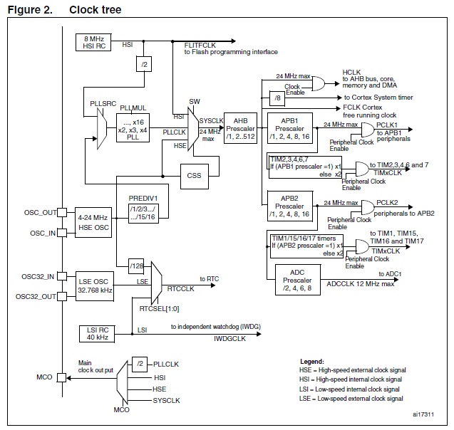
Let us understand - what and where - on the periphery of the system frequency falls from the high-performance AHB bus. On the bus itself, with a divider that allows you to divide the system frequency by 1..512. Actually, the system frequency itself is determined by a multiplexer, designated in the scheme as SW. Frequencies from three sources are fed to the multiplexer: HSI , PLL , HSE ; let's take a quick look at each of them:
HSI (High Speed Internal oscillator)
An internal 8MHz RC circuit that can be used as a source of system frequency or, divided by 2, as an input signal for a PLL (PLL). It can be used in cheap devices, where there are no special requirements for the accuracy and stability of the system frequency, in cheap ones - because external quartz can be dispensed with. The generation frequency depends on temperature, voltage, weather in Taiwan and magnetic storms on the Sun, in general, it floats very much, although the manufacturer calibrates them with an accuracy of 1% at a temperature of 25 ° C - as the temperature changes - the frequency will float, which is unacceptable if depends on the measurement accuracy or time delays. In addition, it can be used as a backup source of system frequency in CSS')
HSE (High Speed External oscillator)
External clock generator - can be both a resonator and an external clock signal. In the case of quartz, it is characterized by high temperature stability, frequency accuracy and durability. From here, the clock pulses go either immediately to the multiplexer, or through the divider 1..16 to the PLL inputPLL (High Speed External oscillator)
Or PLL can multiply the input signal by 2..16 times, while the error is also multiplied, so if the input signal is +1MHz - multiplied by 16 times it will float + -16MHz, besides, the output frequency should not exceed the maximum allowed frequency AhbSo - with the frequency sources sort of figured out - now move on to the topic of the article. Most often, in systems of high reliability, a quartz resonator is used as the source of the system frequency, which can for some reason fail or fail. In order to minimize the bad effects of such a failure in the STM32 and there is CSS . Its essence is as follows: when the HSE starts, the frequency detector is turned on, which when it fails (even if HSE is not the source of the system frequency) immediately turns off the HSE , turns on the HSI , sets it with the source of the system frequency, sends a system frequency error signal to the extended timers and generates an interrupt Notifying HSE Failure Program
Sample code in CoIDE:
code
#include "stm32f10x_rcc.h" #include "stm32f10x_gpio.h" #include "stm32f10x.h" #define LED_PORT GPIOC void LED_GPIO_Configuration(void); void Delay(__IO uint32_t nCount); void NMI_Handler(); int delay_time = 300; int main() { static unsigned long ticks; unsigned char Clock1s; //==================System Clock Init================== // RCC_DeInit(); // HSE RCC_HSEConfig(RCC_HSE_ON); // while(RCC_WaitForHSEStartUp() != SUCCESS); // Clock Security System RCC->CR |= RCC_CR_CSSON; // HSE RCC_SYSCLKConfig(RCC_SYSCLKSource_HSE); // HSI RCC_HSICmd(DISABLE); //======================GPIO Init====================== LED_GPIO_Configuration(); // while(1) { if (ticks++ >= 9999) { ticks = 0; Clock1s = 1; } if (Clock1s) { Clock1s = 0; Delay(delay_time); GPIO_WriteBit(LED_PORT, GPIO_Pin_9, Bit_SET); Delay(delay_time); GPIO_WriteBit(LED_PORT, GPIO_Pin_9, Bit_RESET); } } } // GPIOC void LED_GPIO_Configuration(void) { GPIO_InitTypeDef GPIO_InitStructure; // RCC_APB2PeriphClockCmd(RCC_APB2Periph_GPIOC, ENABLE); // GPIO_InitStructure.GPIO_Pin = GPIO_Pin_8|GPIO_Pin_9; GPIO_InitStructure.GPIO_Mode = GPIO_Mode_Out_PP; GPIO_InitStructure.GPIO_Speed = GPIO_Speed_2MHz; GPIO_Init(GPIOC, &GPIO_InitStructure); } void NMI_Handler() { // CSS RCC->CIR |= RCC_CIR_CSSC; // , // Delay(100); // HSE RCC_HSEConfig(RCC_HSE_ON); // Delay(1); if (RCC_WaitForHSEStartUp() == SUCCESS) { // - HSE RCC_SYSCLKConfig(RCC_SYSCLKSource_HSE); // HSI RCC_HSICmd(DISABLE); // delay_time = 100; } else GPIO_SetBits(GPIOC,GPIO_Pin_8); // - HSI // } // void Delay(__IO uint32_t nCount) { uint32_t i = 0; for (; nCount != 0; i++) { if (i == 1000) { i = 0; nCount--; } } } Video of work:
That's all for now - I used the datasheet , code examples from CoIDE, as well as articles of the respected DI Halta , the interrupt handler is for example only and does not claim to be a super reliable solution - just a demonstration of the possibilities
Source: https://habr.com/ru/post/140761/
All Articles