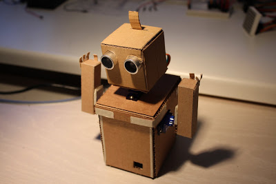
CardboardBot v1.0 - recycle cardboard with brain benefits
The number of attempts to collect a robot from me is incalculable. But, there were not enough materials, then the skills to process them, then some kind of knots, or knowledge, how to put all these things together. If this situation is familiar - I will try to tell my experience of assembling a robot from scrap materials and some items purchased on eBay.
The robot cost me $ 35 and two days of vacation, but the excitement experienced from his first movements cost much more. If you are interested - I ask under the cat (a lot of pictures).
Actually, when all of the above will be within your reach, you can proceed to the assembly.
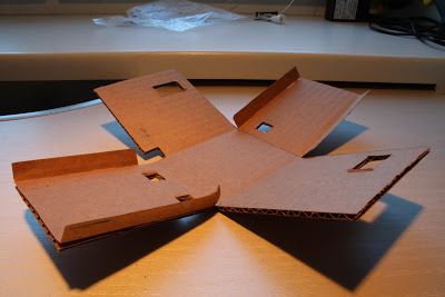
For a start, let's make a cardboard box blank without a cover. The main thing is that the Arduino fits into the base of the box. My base was with a margin of about 5mm on each side - these are tolerances for maneuver, if necessary.
To simplify your life and make the cardboard bend along smooth lines, you should make cuts in places of future bends. The main thing is not to cut a piece. Although, even if this happens, do not worry too much, Scotch will save us.
It is necessary to determine where the back side of our robot will be, and cut holes on this side for the Arduino ports - one for power and one for USB. In order not to pierce, I would advise you to make a mark with a pencil by attaching the board itself. All openings should be made slightly smaller than the actual size - during installation, the cardboard will still bend a little and this will allow the part to be tightly fixed.
In addition, we make holes for the hand servos and provide access to the reset Arduino button.
It is not necessary to glue the blank - it will be difficult to install something into it later. It is better to leave last.
Now the task is even easier - to make the cover. The main thing here is to match the dimensions. The lid will be slightly larger than the base, due to the added width of the walls. In the cover we make a hole for the servo, offset to the front edge. We also make a small hole closer to the back of the cover - it is useful for laying wires (in the photo only the hole for the servo drive is made). To give strength, I pasted the corners of the lid with paper tape.
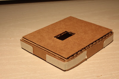
Recommendation: it is better to strengthen all openings for servos. This can be done by gluing an additional cardboard insert from the inside of the box with a slot under the servo drive. There will be only three such inserts, it is very easy to make them, but this will give the structure additional strength and will allow us to fix the servo on the screws, without piercing the cardboard through.
')
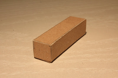
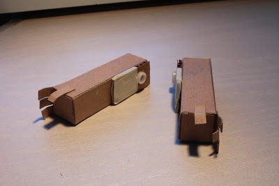
Our hands will be just rectangular boxes. Prepare and cut cardboard.

Glue it into the shape we need.
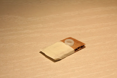
To attach the hand to the servo one of the rocker (supplied) we will drown in a cardboard rectangle, after cutting the shape of the rocker with a knife.

I just taped this design with paper tape. Keeps flimsy, but copes with its task. Hands do not fall off.
We repeat all the steps for assembling the hand once again and glue our attachment to the arms themselves. I also added fingers - it gives the robot some charm.
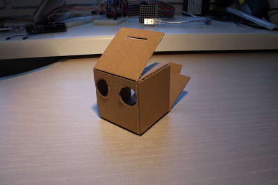
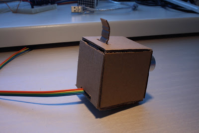
The head will be just a box with holes for the ultrasonic sensor. Putting your hand on the past elements, going easily and simply. The main thing is not to glue the back wall (opposite the slots under the sensor) - it should open freely. Cut the top for the tongue, which will hold this very wall.
View of the head from a different angle.

In addition, it is necessary to make a hole in the back wall, we did the same in the base cover. Through this hole we will pass the wires from the sensor. Another to the top of the back cover you need to glue a strip of cardboard - it will serve as a kind of lock for it.
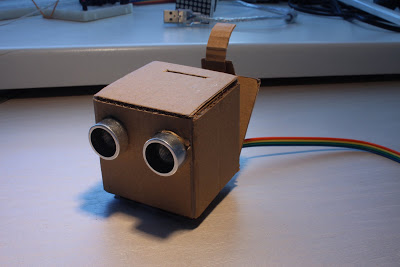
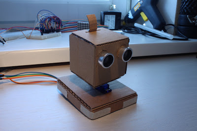
After this, we install the sensor itself with the wiring backed up to it. I use a color loop for this. The head begins to take a finished look.
Look again from the other side.

To attach the head to the servo, we do exactly the same thing that we did for the hands - cut a recess under the rocker in another piece of cardboard (slightly smaller in size than the base area) and seal the rocker with adhesive tape. The resulting element is glued to our head from below.
I forgot to take a photo, but I hope it is clear what to do. We close the head on the tongue glued earlier, pushing it through the slot in the upper part of the box.
In the cover of our base we install the servo drive and fasten it with two cogs that come with it in the kit.

So that the robot can look ahead and turn over its head - before installing the head, it is better to find the middle between the two extreme positions of the servo. This can be done by any remaining rocker. The servo axis should be set to the middle position. Set on the resulting base head.
To warm your own curiosity, you can install the cover with your head on the base. After that, you will still need to remove it, but there is interest.
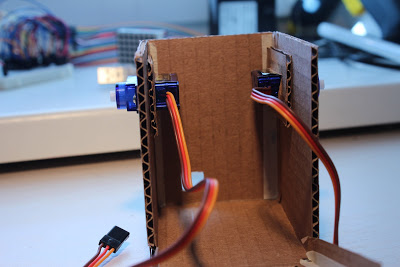
At the base we glue the front wall with the side. Now we insert the servos into the walls of our base so that the axis is shifted closer to the center of the box.

If you look at the back of our robot, the picture will be approximately as follows. By the way, here are perfectly visible inserts from the cardboard under the servos, which I mentioned earlier.
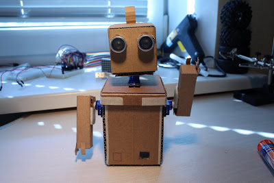
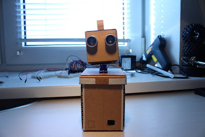
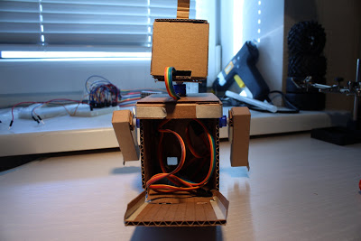
To see how it all looks together, and at the same time assess the future front of work, put the lid on, attach our hands and look at the robot again from both sides.
Familiar photo? Yes, I started the post with it. And yes, indeed, the robot is not yet ready for it, but now it is clear how it will look. View from the other side.
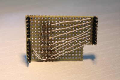
It is clear that in order for all this to work, you need to somehow connect all this to Arduino. Since I do not have Sensor Shield, I had to get out with improvised means. Thus was born the following scheme.

If it is very rough, then you can call it a kind of perverted Arduino Shield - as it is inserted directly into the controller. But somehow my language does not turn to call it a shield, let it be just a scheme.
The main idea is to make it convenient to connect servo drives and a sensor, powering them from the + 5V output of our Arduino. This will allow the robot to work even from the USB port of our computer. From the back side it looks even worse.
Install on the controller.
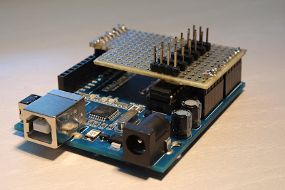
As you can see, ports from the 8th to the 13th remained available, so you can use them in the future. I would certainly make an extension for all ports, but due to the non-standard pitch between two Arduino pads, it is not possible to do this on the breadboard.
Installation is almost coming to an end. It remains to connect our servos and sensor to the board.
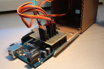
Although it is not of particular importance and you can connect differently, but personally I have obtained the following ports and modules correspondences:
We shove the Arduino with all the wires into the box of our base and glue the back cover of this box. After the glue dries - push the Arduino so that the ports fall into the holes made for them.
It remains only to rejoice - the assembly is fully completed.

To check the performance of all mechanisms we will write a firmware to the robot.
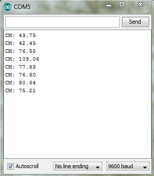
After flashing it to the controller, the robot will come to life. Yes, a normal USB port is quite enough for it to power up - the servos in it consume not so much, and the distance sensor, if you believe the specifications, also consumes a little more LED. We look what happened on the video. I apologize in advance, but for the video I modified the firmware a bit to make it a little more spectacular. All I did was add a few hand movements. However, the firmware described above is quite suitable for testing the robot for operability, it is less and less cluttered up with any nonsense.
At this time on the console you can see the following.
Well, that's all that I wanted to tell. In the future, I plan to slightly improve this robot, perhaps insert a couple of sensors (light and temperature, for example) and actually put it on the shelf - yet this is my first robot. Thanks for attention.
The robot cost me $ 35 and two days of vacation, but the excitement experienced from his first movements cost much more. If you are interested - I ask under the cat (a lot of pictures).
Shopping list
- Cardboard is the main material of our robot. I think many vehicles have equipment boxes lying around - we will need them.
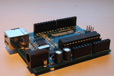
- Arduino - will be the brain of our robot. I only had a Chinese Arduino Uno clone on hand. Price with shipping about $ 20.
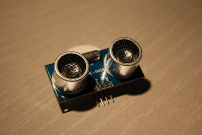
- Ultrasonic Range Finder HC-SR04. The price hovers around $ 4.
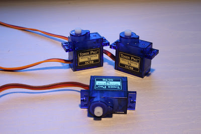
- Three micro servos (labeled “9g” if someone searches). Price about $ 3.5 apiece.
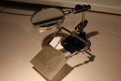
- (optional) Development board for soldering and soldering accessories. You can do without this item by connecting everything just with wires, but in order to have at least a hint of reliability, you will have to solder.
- Scotch tape, glue, scissors, paper knife, simple pencil, ruler.
Actually, when all of the above will be within your reach, you can proceed to the assembly.
Make the torso of the robot
For a start, let's make a cardboard box blank without a cover. The main thing is that the Arduino fits into the base of the box. My base was with a margin of about 5mm on each side - these are tolerances for maneuver, if necessary.
To simplify your life and make the cardboard bend along smooth lines, you should make cuts in places of future bends. The main thing is not to cut a piece. Although, even if this happens, do not worry too much, Scotch will save us.
It is necessary to determine where the back side of our robot will be, and cut holes on this side for the Arduino ports - one for power and one for USB. In order not to pierce, I would advise you to make a mark with a pencil by attaching the board itself. All openings should be made slightly smaller than the actual size - during installation, the cardboard will still bend a little and this will allow the part to be tightly fixed.
In addition, we make holes for the hand servos and provide access to the reset Arduino button.
It is not necessary to glue the blank - it will be difficult to install something into it later. It is better to leave last.
Now the task is even easier - to make the cover. The main thing here is to match the dimensions. The lid will be slightly larger than the base, due to the added width of the walls. In the cover we make a hole for the servo, offset to the front edge. We also make a small hole closer to the back of the cover - it is useful for laying wires (in the photo only the hole for the servo drive is made). To give strength, I pasted the corners of the lid with paper tape.
Recommendation: it is better to strengthen all openings for servos. This can be done by gluing an additional cardboard insert from the inside of the box with a slot under the servo drive. There will be only three such inserts, it is very easy to make them, but this will give the structure additional strength and will allow us to fix the servo on the screws, without piercing the cardboard through.
')
Arms
Our hands will be just rectangular boxes. Prepare and cut cardboard.
Glue it into the shape we need.
To attach the hand to the servo one of the rocker (supplied) we will drown in a cardboard rectangle, after cutting the shape of the rocker with a knife.
I just taped this design with paper tape. Keeps flimsy, but copes with its task. Hands do not fall off.
We repeat all the steps for assembling the hand once again and glue our attachment to the arms themselves. I also added fingers - it gives the robot some charm.
Head around the head
The head will be just a box with holes for the ultrasonic sensor. Putting your hand on the past elements, going easily and simply. The main thing is not to glue the back wall (opposite the slots under the sensor) - it should open freely. Cut the top for the tongue, which will hold this very wall.
View of the head from a different angle.
In addition, it is necessary to make a hole in the back wall, we did the same in the base cover. Through this hole we will pass the wires from the sensor. Another to the top of the back cover you need to glue a strip of cardboard - it will serve as a kind of lock for it.
After this, we install the sensor itself with the wiring backed up to it. I use a color loop for this. The head begins to take a finished look.
Look again from the other side.
To attach the head to the servo, we do exactly the same thing that we did for the hands - cut a recess under the rocker in another piece of cardboard (slightly smaller in size than the base area) and seal the rocker with adhesive tape. The resulting element is glued to our head from below.
I forgot to take a photo, but I hope it is clear what to do. We close the head on the tongue glued earlier, pushing it through the slot in the upper part of the box.
Putting it all together
In the cover of our base we install the servo drive and fasten it with two cogs that come with it in the kit.
So that the robot can look ahead and turn over its head - before installing the head, it is better to find the middle between the two extreme positions of the servo. This can be done by any remaining rocker. The servo axis should be set to the middle position. Set on the resulting base head.
To warm your own curiosity, you can install the cover with your head on the base. After that, you will still need to remove it, but there is interest.
At the base we glue the front wall with the side. Now we insert the servos into the walls of our base so that the axis is shifted closer to the center of the box.
If you look at the back of our robot, the picture will be approximately as follows. By the way, here are perfectly visible inserts from the cardboard under the servos, which I mentioned earlier.
To see how it all looks together, and at the same time assess the future front of work, put the lid on, attach our hands and look at the robot again from both sides.
Familiar photo? Yes, I started the post with it. And yes, indeed, the robot is not yet ready for it, but now it is clear how it will look. View from the other side.
The head of the brain or prepare and insert the controller.
It is clear that in order for all this to work, you need to somehow connect all this to Arduino. Since I do not have Sensor Shield, I had to get out with improvised means. Thus was born the following scheme.
If it is very rough, then you can call it a kind of perverted Arduino Shield - as it is inserted directly into the controller. But somehow my language does not turn to call it a shield, let it be just a scheme.
The main idea is to make it convenient to connect servo drives and a sensor, powering them from the + 5V output of our Arduino. This will allow the robot to work even from the USB port of our computer. From the back side it looks even worse.
Install on the controller.
As you can see, ports from the 8th to the 13th remained available, so you can use them in the future. I would certainly make an extension for all ports, but due to the non-standard pitch between two Arduino pads, it is not possible to do this on the breadboard.
Installation is almost coming to an end. It remains to connect our servos and sensor to the board.
Although it is not of particular importance and you can connect differently, but personally I have obtained the following ports and modules correspondences:
- 2 - right hand servo;
- 3 - left hand servo;
- 4 - head servo;
- 6 - echo of the distance sensor, 7 - its trig.
We shove the Arduino with all the wires into the box of our base and glue the back cover of this box. After the glue dries - push the Arduino so that the ports fall into the holes made for them.
It remains only to rejoice - the assembly is fully completed.
Software part
To check the performance of all mechanisms we will write a firmware to the robot.
#include <Servo.h> #include <Ultrasonic.h> #define RIGHT_HAND_PIN 2 #define LEFT_HAND_PIN 3 #define HEAD_PIN 4 #define TRIGGER_PIN 7 #define ECHO_PIN 6 Servo rightHand; Servo leftHand; Servo head; Ultrasonic ultrasonic(TRIGGER_PIN, ECHO_PIN); void setup() { Serial.begin(9600); rightHand.attach(RIGHT_HAND_PIN); leftHand.attach(LEFT_HAND_PIN); head.attach(HEAD_PIN); } void loop() { head.write(90); delay(1000); float cmMsec; long microsec = ultrasonic.timing(); cmMsec = ultrasonic.convert(microsec, Ultrasonic::CM); Serial.print("CM: "); Serial.println(cmMsec); head.write(135); delay(1000); head.write(45); delay(1000); head.write(90); leftHand.write(0); rightHand.write(0); delay(500); leftHand.write(180); rightHand.write(180); delay(500); } After flashing it to the controller, the robot will come to life. Yes, a normal USB port is quite enough for it to power up - the servos in it consume not so much, and the distance sensor, if you believe the specifications, also consumes a little more LED. We look what happened on the video. I apologize in advance, but for the video I modified the firmware a bit to make it a little more spectacular. All I did was add a few hand movements. However, the firmware described above is quite suitable for testing the robot for operability, it is less and less cluttered up with any nonsense.
At this time on the console you can see the following.
Conclusions and plans
Well, that's all that I wanted to tell. In the future, I plan to slightly improve this robot, perhaps insert a couple of sensors (light and temperature, for example) and actually put it on the shelf - yet this is my first robot. Thanks for attention.
Source: https://habr.com/ru/post/140134/
All Articles