Binary clock do-it-yourself (Mega32, DS1307)
Wishing to collect a binary clock, I did not find an acceptable finished design in the network. Most of the watches had a serious drawback - when the power was turned off, the time settings were lost. By happy coincidence, shortly before that, I began to master the C language and AVR microcontrollers. So, it was decided to back up the knowledge gained with practical experience, and at the same time invent the bicycle. And I also love green flashing LEDs.


')
The problem of saving current settings is perfectly solved by a real-time clock (RTC). My choice fell on the chip DS1307 .
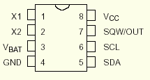
According to the manufacturer, when the power is turned off, it can save time and date for 10 years, consuming the energy of only a lithium battery of type CR2032. Ie the clock continues to tick, while maintaining acceptable accuracy. Time does not go astray by turning on the clock again, we get the real time on the dial, and not the time at the moment it is turned off. The microcircuit communicates with the microcontroller via the “square bus” I 2 C, reporting the exact time and taking its new values.
The choice of the Mega32a microcontroller was dictated by the following factors:
• A sufficient number of ports not to use a dynamic indication, which I do not like, primarily because it irritates eyesight (flashing with a high frequency is unnatural in any case). I met her while playing with PIC microcontrollers in the Proton PICBasic language, and if it is possible not to use the dynamic indication, I would prefer to do so.
• The relatively low cost of 130 rubles (Mega16a, for example, costs the same), and at a discount, in general, 104 rubles.
• Clear QPF-44 package with convenient pinout

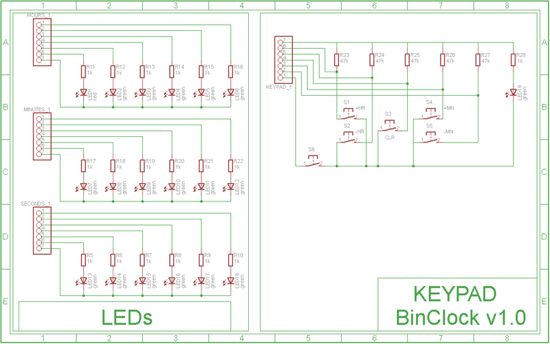
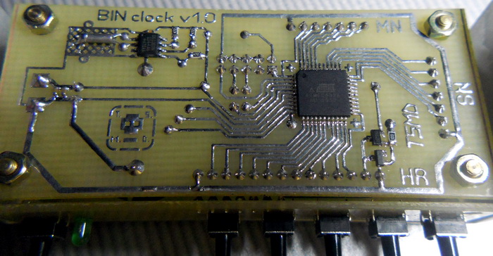
Port "A" displays seconds, port "B" - minutes and port "C" - hours. It is very convenient that you can assign the time values received from DS1307 to the ports without any changes. Buttons (pins 3 - 7) are connected to port “D”, pins 0 and 1 work as clock line (SCL) and serial data line (SDA), respectively. The RTC chip is tuned so that it emits pulses with a frequency of 1 hertz on its seventh leg. This leg is connected to the 3rd pin of port “D”. This port itself is configured as an input, and just in case, internal braces to the power supply are included, duplicated by SMD resistors from the outside. Such actions fully protect from any surprises.
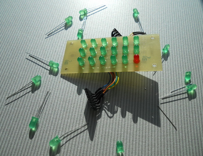
I chose the LEDs in a low luminance matte case. At first, bright diodes in a transparent case were tested, but even at a current of 3 mA they shone too brightly and unevenly, which again caused discomfort. When the voltage drop across the diode is 2 volts, the supply voltage is 5 volts and the resistor is 1 kΩ, the value of the current flowing through the diode will be (5 - 2) / 1000 = 3 mA. This value was chosen empirically, and the brightness of the glow is great for a dim room. If you plan to set the clock in direct sunlight, then the value of the resistors should be reduced, up to 200 ohms, for a brighter glow (thanks to Cap).
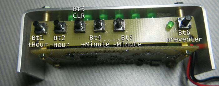
On a separate board with buttons, there is a “fuse” (it will save us from an accidental shot to the head), in the form of one more button Bt6. Time can be edited by first holding it.
The code is written in the CodeVisionAvr environment.
The program begins with the fact that we configure the periphery of the microcontroller.
• Configuring ports (A, B, C - output, D - input)
• Just in case, a pause of 300 ms is provided for the DS1307 to “wake up”
• Initialize the “square bus”
• We configure the RTC chip so that it generates rectangular pulses every second at the SQW / OUT pin.
• Check if the CLR button is pressed. If yes, then reset all values to 0
• Allow global interrupts
Yes, a few words about them. We use INT0 external interrupts on PD2 in a decay, i.e. every second, the program will go to the interrupt handler, in which we read the time values from DS1307 and output them to the LED indicators.
• We leave in an infinite loop, where we poll buttons
• If the button is pressed, add (subtract) an hour (minute) and send a new value via I2C
• Along the way, we check whether the new time values fit into the 24-hour and 60-minute ranges.
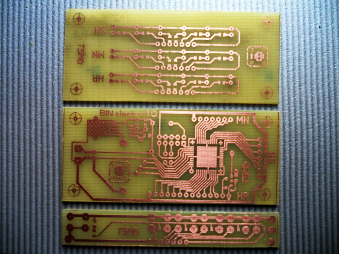
The board is made according to theGreat Space Laser - Ironing Technology on a one-sided PCB. In the manufacture of the upper board, plain paper was used (unsuccessful experiment).
There are many variations of this technology. In my opinion, this one is the best:
1. Cut out the right size piece of PCB.
2. Skins the ends, getting rid of harmful burrs.
3. Lubricate the future board with scouring powder or toothpaste and the hard side of the sponge to scrub it.
4. Dip our piece for a couple of tens of seconds in a weak solution of warm ferric chloride, until a uniform, matte, burgundy-brown surface appears. When pulling out of solution, the liquid must completely wet the surface.
5. Wash off kaku, gently dry, without touching the surface with your fingers, or other fatty. Immediately put on clean paper with copper down to avoid dust or hair.
6. We print out the mirrored pattern on a thin (!) Glossy paper, you can cut it out from a magazine, for example. Do not touch the drawing by hand. Carefully cut, put the picture down.
7. We apply to the prepared piece of textolite, iron through 1-2 layers of clean paper, putting the iron at the maximum temperature. Seconds 10 should be enough, because if you overdo it, the tracks will flatten out and flow over each other. Toner should stick to copper completely.
8. We soak under a stream of warm water, you can leave it in water for 10 minutes. Gently tear off, scrape off the paper. The old toothbrush helps me in this. Remove the remaining pieces of paper with a needle. Toner remains on the PCB.
9. We heat a strong solution of ferric chloride in the water bath, throw our board there and rummage for several minutes (according to the Van't Hoff rule, as the temperature increases by 10 degrees, the reaction rate increases 2 times. Copper disappears right before your eyes. not warm, but have to wait longer.
10. As soon as all unnecessary copper has disappeared, turn off the gas, pull out the board (for example, with tweezers), try to clean the stove and fingers from ferric chloride. Wash it off the board with running water.
11. Take acetone (nail polish remover) and scrub the toner. You can try to scrape it off with a pelt or sponge.
12. Drill holes.
13. Ludim. I use LTI as a flux, and I advise you, but after tinning and soldering, this flux should be washed off (with the same acetone, but rather with an alcohol-gasoline mixture 1: 1), since LITishka has some conductivity.
All work must be carried out in a ventilated room, in the process
many harmful fumes are released.
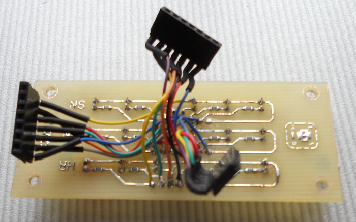
The boards are interconnected by PBS and PLD connectors. The first ones connect to the top board using a thin wiring wire, it can be picked out, for example, from an old LPT cable or adapter.
The second ones are soldered to the bottom board, with the pins leading to the keyboard bending (see photo).

Printed circuit boards in SprintLayout5.0 format are attached. The photos have a couple of shoals, but they are already corrected in the attached files.
For this case, a USBasp programmer was assembled, which can be seen in the photo above. Pretty nice thing, easy to use and you can always carry it with you in your pocket (I hope no one will do that). For the mega32 firmware, you will have to install the Slow SCK jumper.
Physes:
• Low fuse = 0xC4
• High fuse = 0xD9
Our microcontroller is clocked from an internal 8 MHz RC oscillator. I had to disable the JTAG interface on PortC, otherwise some LEDs will not glow.
The board has an ISP10 connector for fast firmware / debugging.
Made of aluminum plate, 40 mm wide and 1.5 mm thick. It drilled 18 holes with a diameter of 5 mm, and 4 holes with a diameter of 3 mm for mounting racks.
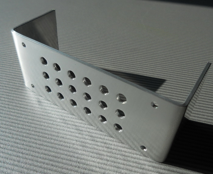
At first the template was printed and pasted on the plate. Further, the pilot holes were drilled with a 1.5 mm drill bit, after which the main holes were drilled with the necessary diameters.
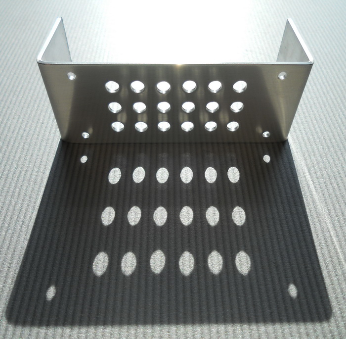
In the end, the plate was bent, sanded with fine sandpaper and polished with GOI paste.
The template is attached to the attached files as a file layout5.0
Repeats the pulses generated by the DS1307 on the 7th leg, i.e. flashing every segundu. A small p-channel MOSFET transistor operates in a key mode, opening and closing in time with pulses. At first I wanted to make a backlight (like Ambilight), for which the CMOS inverter was blinded on a complementary pair of transistors (for sure). But I did not like it. For one LED one transistor is enough, you can even use pnp type bc857. I used unpackaged mosfet irlml6402 or irlml6302.
Sources, hex-file, printed circuit boards, schemes, scheme in proteus and fyuzy are enclosed in this picture in the form of an archive. I do not trust the file storage, I do not have my server yet, therefore, in my amateurish opinion, Habr will be the most reliable storage place. Windows users can access files by opening a saved picture using WinRar.
Yes, here is this picture.

The power supply can be used by anyone capable of delivering 5 volts at a current of 70 mA. USB port is quite suitable for this. The main thing is that the power is “clean” and does not exceed 5 volts. Feeding the clock from the DC-DC converter from the mc34063 chip with a noise level of ~ 50 mV, I noticed glitches when setting the time. Now the device is powered by a switch hanging nearby. It gives out strictly 5 volts. For good, you need to make a foolproof in the form of a diode, and some linear stabilizer of 3.3 - 5 volts.
The absence of the alarm clock and date display functions in the watch is quite reasonable: both are present in the phone, which means that no one will be able to use them in binary watches (thanks to Uncle Occam for this conclusion).
Lebedev, M. B. CodeVisionAVR: A Guide for Beginners
avrdevices.ru/chasi-realynogo-vremeni-ds1307
Scheme
')
RTC
The problem of saving current settings is perfectly solved by a real-time clock (RTC). My choice fell on the chip DS1307 .
According to the manufacturer, when the power is turned off, it can save time and date for 10 years, consuming the energy of only a lithium battery of type CR2032. Ie the clock continues to tick, while maintaining acceptable accuracy. Time does not go astray by turning on the clock again, we get the real time on the dial, and not the time at the moment it is turned off. The microcircuit communicates with the microcontroller via the “square bus” I 2 C, reporting the exact time and taking its new values.
Heart device
The choice of the Mega32a microcontroller was dictated by the following factors:
• A sufficient number of ports not to use a dynamic indication, which I do not like, primarily because it irritates eyesight (flashing with a high frequency is unnatural in any case). I met her while playing with PIC microcontrollers in the Proton PICBasic language, and if it is possible not to use the dynamic indication, I would prefer to do so.
• The relatively low cost of 130 rubles (Mega16a, for example, costs the same), and at a discount, in general, 104 rubles.
• Clear QPF-44 package with convenient pinout
Port "A" displays seconds, port "B" - minutes and port "C" - hours. It is very convenient that you can assign the time values received from DS1307 to the ports without any changes. Buttons (pins 3 - 7) are connected to port “D”, pins 0 and 1 work as clock line (SCL) and serial data line (SDA), respectively. The RTC chip is tuned so that it emits pulses with a frequency of 1 hertz on its seventh leg. This leg is connected to the 3rd pin of port “D”. This port itself is configured as an input, and just in case, internal braces to the power supply are included, duplicated by SMD resistors from the outside. Such actions fully protect from any surprises.
LEDs
I chose the LEDs in a low luminance matte case. At first, bright diodes in a transparent case were tested, but even at a current of 3 mA they shone too brightly and unevenly, which again caused discomfort. When the voltage drop across the diode is 2 volts, the supply voltage is 5 volts and the resistor is 1 kΩ, the value of the current flowing through the diode will be (5 - 2) / 1000 = 3 mA. This value was chosen empirically, and the brightness of the glow is great for a dim room. If you plan to set the clock in direct sunlight, then the value of the resistors should be reduced, up to 200 ohms, for a brighter glow (thanks to Cap).
Buttons
On a separate board with buttons, there is a “fuse” (it will save us from an accidental shot to the head), in the form of one more button Bt6. Time can be edited by first holding it.
Soft
The code is written in the CodeVisionAvr environment.
The program begins with the fact that we configure the periphery of the microcontroller.
• Configuring ports (A, B, C - output, D - input)
• Just in case, a pause of 300 ms is provided for the DS1307 to “wake up”
• Initialize the “square bus”
• We configure the RTC chip so that it generates rectangular pulses every second at the SQW / OUT pin.
• Check if the CLR button is pressed. If yes, then reset all values to 0
• Allow global interrupts
Yes, a few words about them. We use INT0 external interrupts on PD2 in a decay, i.e. every second, the program will go to the interrupt handler, in which we read the time values from DS1307 and output them to the LED indicators.
• We leave in an infinite loop, where we poll buttons
• If the button is pressed, add (subtract) an hour (minute) and send a new value via I2C
• Along the way, we check whether the new time values fit into the 24-hour and 60-minute ranges.
Printed circuit board
The board is made according to the
There are many variations of this technology. In my opinion, this one is the best:
1. Cut out the right size piece of PCB.
2. Skins the ends, getting rid of harmful burrs.
3. Lubricate the future board with scouring powder or toothpaste and the hard side of the sponge to scrub it.
4. Dip our piece for a couple of tens of seconds in a weak solution of warm ferric chloride, until a uniform, matte, burgundy-brown surface appears. When pulling out of solution, the liquid must completely wet the surface.
5. Wash off kaku, gently dry, without touching the surface with your fingers, or other fatty. Immediately put on clean paper with copper down to avoid dust or hair.
6. We print out the mirrored pattern on a thin (!) Glossy paper, you can cut it out from a magazine, for example. Do not touch the drawing by hand. Carefully cut, put the picture down.
7. We apply to the prepared piece of textolite, iron through 1-2 layers of clean paper, putting the iron at the maximum temperature. Seconds 10 should be enough, because if you overdo it, the tracks will flatten out and flow over each other. Toner should stick to copper completely.
8. We soak under a stream of warm water, you can leave it in water for 10 minutes. Gently tear off, scrape off the paper. The old toothbrush helps me in this. Remove the remaining pieces of paper with a needle. Toner remains on the PCB.
9. We heat a strong solution of ferric chloride in the water bath, throw our board there and rummage for several minutes (according to the Van't Hoff rule, as the temperature increases by 10 degrees, the reaction rate increases 2 times. Copper disappears right before your eyes. not warm, but have to wait longer.
10. As soon as all unnecessary copper has disappeared, turn off the gas, pull out the board (for example, with tweezers), try to clean the stove and fingers from ferric chloride. Wash it off the board with running water.
11. Take acetone (nail polish remover) and scrub the toner. You can try to scrape it off with a pelt or sponge.
12. Drill holes.
13. Ludim. I use LTI as a flux, and I advise you, but after tinning and soldering, this flux should be washed off (with the same acetone, but rather with an alcohol-gasoline mixture 1: 1), since LITishka has some conductivity.
All work must be carried out in a ventilated room, in the process
many harmful fumes are released.
The boards are interconnected by PBS and PLD connectors. The first ones connect to the top board using a thin wiring wire, it can be picked out, for example, from an old LPT cable or adapter.
The second ones are soldered to the bottom board, with the pins leading to the keyboard bending (see photo).
Printed circuit boards in SprintLayout5.0 format are attached. The photos have a couple of shoals, but they are already corrected in the attached files.
Microcontroller firmware
For this case, a USBasp programmer was assembled, which can be seen in the photo above. Pretty nice thing, easy to use and you can always carry it with you in your pocket (I hope no one will do that). For the mega32 firmware, you will have to install the Slow SCK jumper.
Physes:
• Low fuse = 0xC4
• High fuse = 0xD9
Our microcontroller is clocked from an internal 8 MHz RC oscillator. I had to disable the JTAG interface on PortC, otherwise some LEDs will not glow.
The board has an ISP10 connector for fast firmware / debugging.
Front panel
Made of aluminum plate, 40 mm wide and 1.5 mm thick. It drilled 18 holes with a diameter of 5 mm, and 4 holes with a diameter of 3 mm for mounting racks.
At first the template was printed and pasted on the plate. Further, the pilot holes were drilled with a 1.5 mm drill bit, after which the main holes were drilled with the necessary diameters.
In the end, the plate was bent, sanded with fine sandpaper and polished with GOI paste.
The template is attached to the attached files as a file layout5.0
Red LED in the upper left corner
Repeats the pulses generated by the DS1307 on the 7th leg, i.e. flashing every segundu. A small p-channel MOSFET transistor operates in a key mode, opening and closing in time with pulses. At first I wanted to make a backlight (like Ambilight), for which the CMOS inverter was blinded on a complementary pair of transistors (for sure). But I did not like it. For one LED one transistor is enough, you can even use pnp type bc857. I used unpackaged mosfet irlml6402 or irlml6302.
Files
Sources, hex-file, printed circuit boards, schemes, scheme in proteus and fyuzy are enclosed in this picture in the form of an archive. I do not trust the file storage, I do not have my server yet, therefore, in my amateurish opinion, Habr will be the most reliable storage place. Windows users can access files by opening a saved picture using WinRar.
Yes, here is this picture.
Video
Conclusion
The power supply can be used by anyone capable of delivering 5 volts at a current of 70 mA. USB port is quite suitable for this. The main thing is that the power is “clean” and does not exceed 5 volts. Feeding the clock from the DC-DC converter from the mc34063 chip with a noise level of ~ 50 mV, I noticed glitches when setting the time. Now the device is powered by a switch hanging nearby. It gives out strictly 5 volts. For good, you need to make a foolproof in the form of a diode, and some linear stabilizer of 3.3 - 5 volts.
The absence of the alarm clock and date display functions in the watch is quite reasonable: both are present in the phone, which means that no one will be able to use them in binary watches (thanks to Uncle Occam for this conclusion).
Used materials
Lebedev, M. B. CodeVisionAVR: A Guide for Beginners
avrdevices.ru/chasi-realynogo-vremeni-ds1307
Source: https://habr.com/ru/post/139647/
All Articles