STM32F1xx - Developer Tools and FreeRTOS
Good afternoon, dear habrovchane. In my previous articles ( STM32F1xx - we treat arduino dependency together , STM32F1xx - we continue treatment of arduino dependency with LCD ) I tried to highlight the issues of transition from 8-bit microcontrollers to new 32-bit STM32F1xx.
In the process of working with them, I, of course, chose the tools for myself “by the hand” - that is, I tried to find the most convenient debugging boards for me, programmers, IDE. In this article I want to share with you a few thoughts on this matter, as well as describe the build process in the chosen IDE of the real-time operating system FreeRTOS.
Traditionally start with iron.
In previous articles, the core of the system was STM32VLDISCOVERY .
The fee is certainly good, and impresses with the fact that its price is only 300 rubles. In principle, a good tool to begin to get acquainted with this family of microcontrollers. But.
The fact is that when choosing a debug board, you always want to keep the balance of quantity and quality, that is, on the one hand, you have everything you need for work, on the other hand, you don’t want the board to turn into a huge and expensive monster. At STM32VLDISCOVERY, the balance is shifted towards low cost and minimalism.
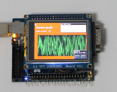
Climbing on e-bay, I found a more convenient, in my opinion, charge, which I present to your attention. Here she is:
Mini-STM32
For 46 dollars we are offered:
In addition, at a separate request, for $ 28, the seller will attach a J-Link-compatible programmer to the board (or, simply, a real Segger J-Link clone, shamelessly masquerading under it), with a cable that is fully compatible with the connector on the board.
Summarizing the above, I consider this board a thing of first necessity for a person who decided to start studying STM32F1xx microcontrollers.
')
Now for the IDE. Initially, I chose Keil uVision, as I once worked with it.
Well, what can I say - I worked in Keila enough, and in principle you can reconcile with him. But, hand on heart - it is terrible there. It is also terrible as the idea of IAR'a, in my opinion.
IAR and Keil are recognized leaders in the development of compilers, they can’t take this from them, but I still cannot understand why, having such compilers, they continue to pull their IDEs, which are stuck in convenience at the 2002 level. As an example I can cite Texas Instruments - they also had their own IDE before, in the appendage to the compiler. Then they got tired of it, they took Eclipse, finished it, screwed it to their compiler and profiler, and got a great product. Why Keil and IAR will not do this for me remains a mystery, but in my opinion their IDEs are not as convenient as they could be. Irritating is not very convenient syntax highlighting, the complete absence of code-completion, not the most convenient code navigation. Plus, uVision often fell at me, but this can be attributed to the programmer driver.
Anyway, I began to look for an alternative and found it in the form of CooCox IDE .

This is a free Eclipse-based development environment, which is designed, of course, to work with GCC.
Of the advantages, I would like to note all the advantages of the Eclipse - easy navigation, there is code completion, etc.
In addition, a convenient processor peripheral viewer is bolted, I liked it more than Kaylovsky. It is very convenient to have a repository of components - simply speaking, when starting a project, we, as a wizard, select the processor we need from the list, and then tick the ones from the Standard Peripheral Library modules that we would like to use, and they automatically connect to the project (About a little more in the next section of the article). You can also immediately see the examples included with this SPL module and help with its functions.
CooCox IDE also absorbed the minuses from Eclipse, which is heavy - it consumes about 180 meters of RAM from me, occupying 800 megabytes of disk space.
Another disadvantage is her work with this very J-Link-com. Debugging takes place through an application from the creators of J-Link, which provides a standard gdb interface, but for some reason the environment restarts at each debug, unlike the same keil (which works through its own dlls).
Therefore, the start of debugging in Kayla begins in a second, but in CooCox, in about 20 seconds. Perhaps this can be somehow corrected by settings, but I haven’t seen such settings yet, so I will be grateful if someone tells me.
Nevertheless, I still stopped at CooCox - if you are also not satisfied with the IDE from Keil or IAR, or you do not want to use broken software and prefer open source - download it without thinking.
Much has been said about the FreeRTOS operating system, in particular, in Habré (for example, one of the articles: FreeRTOS: introduction )
I also decided to join this technology and expand my arsenal of tools, especially since FreeRTOS does not impose any HAL (Hardware Abstraction Layer, hardware abstraction layer, drivers, that is), and provides only tools for working with tasks, synchronization and inter-process interaction, so in many cases will be very convenient.
Let's take a closer look at what we need to use FreeRTOS with CooCox IDE on our Mini-STM32 board.
In fact, everything is very simple. Architectural porting (porting the code required by the scheduler for the Cortex M3 architecture) has long been done, and we need to, in fact, just make the right project for CooCox.
We start by downloading the FreeRTOS sources from their official website.
Here is the direct link: http://sourceforge.net/projects/freertos/files/ .
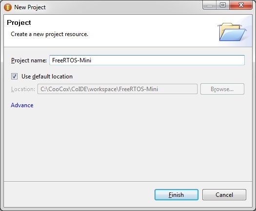
In the meantime, we are creating a new project in CooCox, I called it FreeRTOS-Mini.
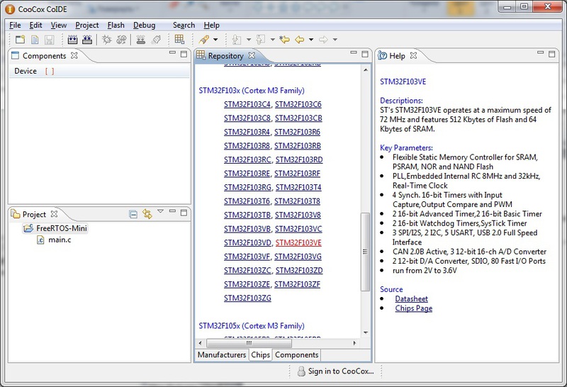
We select the manufacturer ST in the wizard, in the list of chips - the chip on which the debug board is built, STM32F103VE.

After this, we already see the already mentioned window of the repository of components that are parts of the SPL.
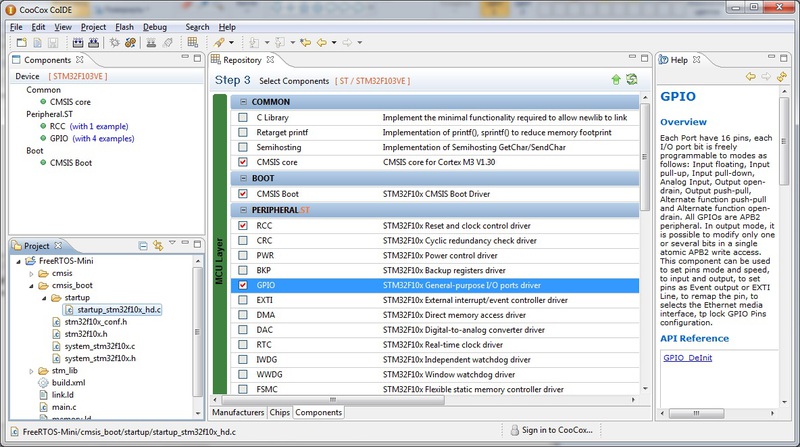
There we select CMSIS Core and CMSIS Boot - this is the actual CMSIS kernel and the start code, which sets up and pulls the main ()
By the way, pay attention - in CooCox, the start code is written entirely in C, not a single asm line. It lies in the file cmsis_boot \ startup \ startup_stm32f10x_hd.c - remember this way, we will need to correct something there. At the same time, we add a GPIO module to the project, so that there is something to do in the FreeRTOS test task. This module automatically pulls the dependent RCC responsible for setting up clocks.
Now we return to the downloaded source codes of FreeRTOS. To begin, copy the entire folder to the folder with our project. After, we will start to delete the excess. So, personally, under my knife, the contents of the Demo folder went right away - there are demo applications for different controllers, you don’t need the entire folder in any case, but if you want, you can leave what applies to STM32F103. The only thing that we definitely need from there is the FreeRTOS kernel settings file, which can be taken from any suitable project, let's say from here: Demo \ CORTEX_STM32F103_Primer_GCC \ FreeRTOSConfig.h
It can be copied to any folder of the desktop, I personally put it at the very root of the project, next to main.c
Further, in the source \ portable folder there are a lot of sub-folders, where the code for different compilers and environments lies. Go to the folder source \ portable \ GCC \ ARM_CM3 , copy it two levels higher, in source \ portable . Pay attention to the folder source \ portable \ MemMang - we also need it. Therefore, we delete everything except source \ portable \ MemMang and fresh source \ portable \ ARM_CM3
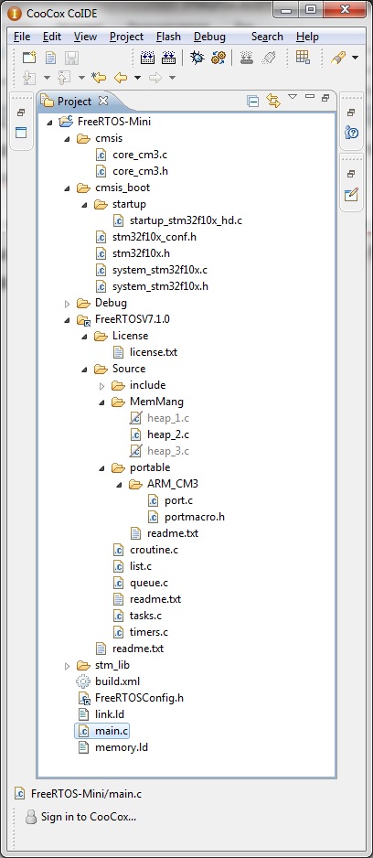
After that, right-click in the CooCox search explorer, click Add Linked Folder and add our folder with the prepared FreeRTOS sources. As a result, you should get this project tree:
Now we start to edit the project files. Let's start with the kernel settings. From there, we will need to remove only a couple of lines related to the old project - the left, unnecessary us.
Everything else can be left unchanged, but you can read an article about configuring the FreeRTOS kernel and change the options as needed, we are not going to do that now.
Now we go to the startup code ( cmsis_boot \ startup \ startup_stm32f10x_hd.c ) and do the following: we find the lines:
I have lines 114-122, and add the following code after them:
These are interrupt handlers from the OS kernel, which are declared in the port.c. file. Now we need to stuff them into the interrupt vector that comes below (lines 129-209):
Accordingly, we change the vector as written in the above code, replacing the lines marked SVCall Handler , PendSV Handler , SysTick Handler with vPortSVCHandler , xPortPendSVHandler and xPortSysTickHandler, respectively.
UPD:
In the comments I was prompted by a more elegant option than picking the starting file. It is enough just to override handlers with the following defines:
After that, open the Source \ MemMang folder in the project tree, and select the implementation of the management memory that suits us. Read more about it here: FreeRTOS Memory Management .
In short, file number 1 is a simplified implementation with memory allocation, but without release, file number 2 is a more advanced implementation that allows memory release, and number 3 is an implementation that will require a library with implemented malloc and free. I chose the second implementation, excluding the remaining two files from the compilation by right-clicking on the file name in the project tree and selecting Exclude from build .
It remains quite a bit - open the file main.c, add the necessary SPL files we need there:
Includes from FreeRTOS:
After declaring the function that will be called before the start of the scheduler, in accordance with the recommendations in this form:
And the function that will play the role of our test task, like this:
The implementation of functions looks like this:
For testing purposes, I did not write anything useful, the task just lights the LED on the board.
The main () function itself remains, which will start the task and the scheduler:
That's basically it. It remains to configure debugging - for this, click “Debug configuration”, in the Debugger tab, select our programmer (J-Link) and the JTAG port.
We tick the Run To Main checkbox in order not to wallow in the startup code, in the GDBServer cmdline tool line we specify the path to the executable with the programmer (you can download it from the Segger website), I have C: \ SEGGER \ JLinkARM_V440b \ JLinkGDBServerCL.exe
After we press Apply and Close.
Now we compile our project and click on debug - if everything worked out, after the aplode and execution, the LED should light up.
The right choice of developer tools will certainly ensure the most rapid and comfortable mastering of new technologies. I hope that by highlighting the Mini-STM32 and CooCox IDE debug board in this article, I helped the developers to look at the new tool. As for the operating system, FreeRTOS is undoubtedly a very powerful tool, and, in my opinion, a good step to move from programming the firmware head-on to the use of operational systems.
An eBay page where you can buy a debug board
CooCox official website
FreeRTOS official website
Russian manual on FreeRTOS
In the process of working with them, I, of course, chose the tools for myself “by the hand” - that is, I tried to find the most convenient debugging boards for me, programmers, IDE. In this article I want to share with you a few thoughts on this matter, as well as describe the build process in the chosen IDE of the real-time operating system FreeRTOS.
Iron
Traditionally start with iron.
In previous articles, the core of the system was STM32VLDISCOVERY .
The fee is certainly good, and impresses with the fact that its price is only 300 rubles. In principle, a good tool to begin to get acquainted with this family of microcontrollers. But.
The fact is that when choosing a debug board, you always want to keep the balance of quantity and quality, that is, on the one hand, you have everything you need for work, on the other hand, you don’t want the board to turn into a huge and expensive monster. At STM32VLDISCOVERY, the balance is shifted towards low cost and minimalism.
Climbing on e-bay, I found a more convenient, in my opinion, charge, which I present to your attention. Here she is:
Mini-STM32
For 46 dollars we are offered:
- Microcontroller STM32F103VE, having onboard 512 kilobytes of flash and 64 kilobytes of RAM, USB, SDIO (that is, it will be much faster to read from a card than on an SPI). In addition, since the board has a 100-foot version of it, it has enough external pins to manage memory through the FSMC. FSMC is a Flexible Static Memory Controller, a very convenient static memory controller, starting with SRAM itself and ending with NAND flash drives. By setting it up and connecting the memory to the control pins, we get our memory mapped to the controller's address space. That is, from now on, all interactions with it will be transparent to us and equivalent to simply writing to RAM.
- Color TFT-display with a resolution of 320x240 and a pre-installed resistive touch-screen. The display is placed on the board as a module, if desired, you can unscrew the small stands to which it is attached, and use the board without it. In addition to the display module, the display module also includes a step-up converter for powering its backlight, as well as a touch-screen controller that is controlled via SPI. In addition, the connector is connected to the above-mentioned FSMC, which makes it more convenient to interact with it.
For example, here is the entry in the display registers, and then in its memory, using DMA:#define LCDRegister (*((volatile u16*) 0x60000000)) #define LCDMemory (*((volatile u16*) 0x60020000)) //… void LCDWriteRegister(unsigned short reg, unsigned short data) { LCDRegister=reg; LCDMemory=data; } void LCDBeginRAMWrite() { LCDRegister=CTR_WRITE_DATA; } int main(void) { //… RCC_AHBPeriphClockCmd(RCC_AHBPeriph_DMA1, ENABLE); DMA_InitTypeDef DMA_InitStructure; DMA_DeInit(DMA1_Channel1); // - DMA_InitStructure.DMA_PeripheralBaseAddr = (u32) PlasmaBuffer1; // « » DMA_InitStructure.DMA_MemoryBaseAddr = (u32)(&LCDMemory); DMA_InitStructure.DMA_DIR = DMA_DIR_PeripheralSRC; DMA_InitStructure.DMA_BufferSize = PLASMA_WIDTH*PLASMA_HEIGHT; DMA_InitStructure.DMA_PeripheralInc = DMA_PeripheralInc_Enable; DMA_InitStructure.DMA_MemoryInc = DMA_MemoryInc_Disable; DMA_InitStructure.DMA_PeripheralDataSize = DMA_PeripheralDataSize_Byte; DMA_InitStructure.DMA_MemoryDataSize = DMA_MemoryDataSize_HalfWord; DMA_InitStructure.DMA_Mode = DMA_Mode_Normal; DMA_InitStructure.DMA_Priority = DMA_Priority_High; DMA_InitStructure.DMA_M2M = DMA_M2M_Enable; DMA_Init(DMA1_Channel1, &DMA_InitStructure); //… //, LCDBeginRAMWrite(); DMA_SetCurrDataCounter(DMA1_Channel1, PLASMA_WIDTH*PLASMA_HEIGHT); DMA_Cmd(DMA1_Channel1, ENABLE); }
After the last line is completed, the control is returned to the program, so you can immediately begin the calculation of the next frame while the first one is output via DMA. - A micro-SD slot connected to the control pins of the SDMO STM controller. The situation is the same as with the display - we have a fast and convenient way to communicate with the memory card, much faster than SPI.
- USB connector and accompanying schematics. As you know, USB host determines the presence of a device on the bus on the pull-up resistor. Accordingly, in order to be able to perform any actions first and only then give a signal to the host “I am connected!” You need to connect a pull-up resistor through a transistor switch
On the board, this has already been done for us, the control transistor is connected to one of the GPIO pins, the pull-up resistors are tuned to Full-Speed USB. - Unused pins are placed on a two-row forty-kopeck connector, the second connector is a display connector, the third is a connector for a programmer, J-Link compatible.
- Of nice bonuses - the board also has a connector for a battery that powers the RTC, a two-meter SPI flash drive, one controlled LED, one button, a good stabilizer for USB power and a max232 converter, along with a connector for a com-port.
The latter, of course, in my opinion is the most superfluous part in the entire board, only occupying space, but okay, so be it.
In addition, at a separate request, for $ 28, the seller will attach a J-Link-compatible programmer to the board (or, simply, a real Segger J-Link clone, shamelessly masquerading under it), with a cable that is fully compatible with the connector on the board.
Summarizing the above, I consider this board a thing of first necessity for a person who decided to start studying STM32F1xx microcontrollers.
')
Soft
Now for the IDE. Initially, I chose Keil uVision, as I once worked with it.
Well, what can I say - I worked in Keila enough, and in principle you can reconcile with him. But, hand on heart - it is terrible there. It is also terrible as the idea of IAR'a, in my opinion.
IAR and Keil are recognized leaders in the development of compilers, they can’t take this from them, but I still cannot understand why, having such compilers, they continue to pull their IDEs, which are stuck in convenience at the 2002 level. As an example I can cite Texas Instruments - they also had their own IDE before, in the appendage to the compiler. Then they got tired of it, they took Eclipse, finished it, screwed it to their compiler and profiler, and got a great product. Why Keil and IAR will not do this for me remains a mystery, but in my opinion their IDEs are not as convenient as they could be. Irritating is not very convenient syntax highlighting, the complete absence of code-completion, not the most convenient code navigation. Plus, uVision often fell at me, but this can be attributed to the programmer driver.
Anyway, I began to look for an alternative and found it in the form of CooCox IDE .
This is a free Eclipse-based development environment, which is designed, of course, to work with GCC.
Of the advantages, I would like to note all the advantages of the Eclipse - easy navigation, there is code completion, etc.
In addition, a convenient processor peripheral viewer is bolted, I liked it more than Kaylovsky. It is very convenient to have a repository of components - simply speaking, when starting a project, we, as a wizard, select the processor we need from the list, and then tick the ones from the Standard Peripheral Library modules that we would like to use, and they automatically connect to the project (About a little more in the next section of the article). You can also immediately see the examples included with this SPL module and help with its functions.
CooCox IDE also absorbed the minuses from Eclipse, which is heavy - it consumes about 180 meters of RAM from me, occupying 800 megabytes of disk space.
Another disadvantage is her work with this very J-Link-com. Debugging takes place through an application from the creators of J-Link, which provides a standard gdb interface, but for some reason the environment restarts at each debug, unlike the same keil (which works through its own dlls).
Therefore, the start of debugging in Kayla begins in a second, but in CooCox, in about 20 seconds. Perhaps this can be somehow corrected by settings, but I haven’t seen such settings yet, so I will be grateful if someone tells me.
Nevertheless, I still stopped at CooCox - if you are also not satisfied with the IDE from Keil or IAR, or you do not want to use broken software and prefer open source - download it without thinking.
CooCox and FreeRTOS
Much has been said about the FreeRTOS operating system, in particular, in Habré (for example, one of the articles: FreeRTOS: introduction )
I also decided to join this technology and expand my arsenal of tools, especially since FreeRTOS does not impose any HAL (Hardware Abstraction Layer, hardware abstraction layer, drivers, that is), and provides only tools for working with tasks, synchronization and inter-process interaction, so in many cases will be very convenient.
Let's take a closer look at what we need to use FreeRTOS with CooCox IDE on our Mini-STM32 board.
In fact, everything is very simple. Architectural porting (porting the code required by the scheduler for the Cortex M3 architecture) has long been done, and we need to, in fact, just make the right project for CooCox.
We start by downloading the FreeRTOS sources from their official website.
Here is the direct link: http://sourceforge.net/projects/freertos/files/ .
In the meantime, we are creating a new project in CooCox, I called it FreeRTOS-Mini.
We select the manufacturer ST in the wizard, in the list of chips - the chip on which the debug board is built, STM32F103VE.
After this, we already see the already mentioned window of the repository of components that are parts of the SPL.
There we select CMSIS Core and CMSIS Boot - this is the actual CMSIS kernel and the start code, which sets up and pulls the main ()
By the way, pay attention - in CooCox, the start code is written entirely in C, not a single asm line. It lies in the file cmsis_boot \ startup \ startup_stm32f10x_hd.c - remember this way, we will need to correct something there. At the same time, we add a GPIO module to the project, so that there is something to do in the FreeRTOS test task. This module automatically pulls the dependent RCC responsible for setting up clocks.
Now we return to the downloaded source codes of FreeRTOS. To begin, copy the entire folder to the folder with our project. After, we will start to delete the excess. So, personally, under my knife, the contents of the Demo folder went right away - there are demo applications for different controllers, you don’t need the entire folder in any case, but if you want, you can leave what applies to STM32F103. The only thing that we definitely need from there is the FreeRTOS kernel settings file, which can be taken from any suitable project, let's say from here: Demo \ CORTEX_STM32F103_Primer_GCC \ FreeRTOSConfig.h
It can be copied to any folder of the desktop, I personally put it at the very root of the project, next to main.c
Further, in the source \ portable folder there are a lot of sub-folders, where the code for different compilers and environments lies. Go to the folder source \ portable \ GCC \ ARM_CM3 , copy it two levels higher, in source \ portable . Pay attention to the folder source \ portable \ MemMang - we also need it. Therefore, we delete everything except source \ portable \ MemMang and fresh source \ portable \ ARM_CM3
After that, right-click in the CooCox search explorer, click Add Linked Folder and add our folder with the prepared FreeRTOS sources. As a result, you should get this project tree:
Now we start to edit the project files. Let's start with the kernel settings. From there, we will need to remove only a couple of lines related to the old project - the left, unnecessary us.
/* Library includes. */ #include "stm32f10x_lib.h" Everything else can be left unchanged, but you can read an article about configuring the FreeRTOS kernel and change the options as needed, we are not going to do that now.
Now we go to the startup code ( cmsis_boot \ startup \ startup_stm32f10x_hd.c ) and do the following: we find the lines:
/*----------Function prototypes-----------------------------------------------*/ extern int main(void); /*!< The entry point for the application. */ extern void SystemInit(void); /*!< Setup the microcontroller system(CMSIS) */ void Default_Reset_Handler(void); /*!< Default reset handler */ static void Default_Handler(void); /*!< Default exception handler */ I have lines 114-122, and add the following code after them:
extern void xPortPendSVHandler( void ) __attribute__ (( naked )); extern void xPortSysTickHandler( void ); extern void vPortSVCHandler( void ) __attribute__ (( naked )); These are interrupt handlers from the OS kernel, which are declared in the port.c. file. Now we need to stuff them into the interrupt vector that comes below (lines 129-209):
__attribute__ ((section(".isr_vector"))) void (* const g_pfnVectors[])(void) = { /*----------Core Exceptions-------------------------------------------------*/ (void *)&pulStack[STACK_SIZE-1], /*!< The initial stack pointer */ Reset_Handler, /*!< Reset Handler */ NMI_Handler, /*!< NMI Handler */ HardFault_Handler, /*!< Hard Fault Handler */ MemManage_Handler, /*!< MPU Fault Handler */ BusFault_Handler, /*!< Bus Fault Handler */ UsageFault_Handler, /*!< Usage Fault Handler */ 0,0,0,0, /*!< Reserved */ vPortSVCHandler, /*!< SVCall Handler */ DebugMon_Handler, /*!< Debug Monitor Handler */ 0, /*!< Reserved */ xPortPendSVHandler, /*!< PendSV Handler */ xPortSysTickHandler, /*!< SysTick Handler */ Accordingly, we change the vector as written in the above code, replacing the lines marked SVCall Handler , PendSV Handler , SysTick Handler with vPortSVCHandler , xPortPendSVHandler and xPortSysTickHandler, respectively.
UPD:
In the comments I was prompted by a more elegant option than picking the starting file. It is enough just to override handlers with the following defines:
#define vPortSVCHandler SVC_Handler #define xPortPendSVHandler PendSV_Handler #define vPortSVCHandler SVC_Handler #define xPortSysTickHandler SysTick_Handler After that, open the Source \ MemMang folder in the project tree, and select the implementation of the management memory that suits us. Read more about it here: FreeRTOS Memory Management .
In short, file number 1 is a simplified implementation with memory allocation, but without release, file number 2 is a more advanced implementation that allows memory release, and number 3 is an implementation that will require a library with implemented malloc and free. I chose the second implementation, excluding the remaining two files from the compilation by right-clicking on the file name in the project tree and selecting Exclude from build .
It remains quite a bit - open the file main.c, add the necessary SPL files we need there:
#include "stm32f10x.h" #include "stm32f10x_gpio.h" #include "stm32f10x_rcc.h" Includes from FreeRTOS:
#include "FreeRTOS.h" #include "task.h" #include "queue.h" After declaring the function that will be called before the start of the scheduler, in accordance with the recommendations in this form:
static void prvSetupHardware( void ); And the function that will play the role of our test task, like this:
static void prvLedBlink( void *pvParameters ); The implementation of functions looks like this:
void prvSetupHardware() { GPIO_InitTypeDef GPIO_InitStructure; RCC_APB2PeriphClockCmd(RCC_APB2Periph_GPIOB, ENABLE); GPIO_InitStructure.GPIO_Pin = GPIO_Pin_5; GPIO_InitStructure.GPIO_Mode = GPIO_Mode_Out_PP; GPIO_InitStructure.GPIO_Speed = GPIO_Speed_50MHz; GPIO_Init(GPIOB, &GPIO_InitStructure); } void prvLedBlink( void *pvParameters ) { GPIO_SetBits(GPIOB,GPIO_Pin_5); while(1); } For testing purposes, I did not write anything useful, the task just lights the LED on the board.
The main () function itself remains, which will start the task and the scheduler:
int main(void) { prvSetupHardware(); xTaskCreate(prvLedBlink,(signed char*)"LED",configMINIMAL_STACK_SIZE, NULL, tskIDLE_PRIORITY + 1, NULL); /* Start the scheduler. */ vTaskStartScheduler(); while(1); } That's basically it. It remains to configure debugging - for this, click “Debug configuration”, in the Debugger tab, select our programmer (J-Link) and the JTAG port.
We tick the Run To Main checkbox in order not to wallow in the startup code, in the GDBServer cmdline tool line we specify the path to the executable with the programmer (you can download it from the Segger website), I have C: \ SEGGER \ JLinkARM_V440b \ JLinkGDBServerCL.exe
After we press Apply and Close.
Now we compile our project and click on debug - if everything worked out, after the aplode and execution, the LED should light up.
Conclusion
The right choice of developer tools will certainly ensure the most rapid and comfortable mastering of new technologies. I hope that by highlighting the Mini-STM32 and CooCox IDE debug board in this article, I helped the developers to look at the new tool. As for the operating system, FreeRTOS is undoubtedly a very powerful tool, and, in my opinion, a good step to move from programming the firmware head-on to the use of operational systems.
Links
An eBay page where you can buy a debug board
CooCox official website
FreeRTOS official website
Russian manual on FreeRTOS
Source: https://habr.com/ru/post/139601/
All Articles