Programming Siemens PLC on Simatic Step7
Good afternoon, habrovchane! Climbing along Habr, I found only a few topics in which the phrase "Simatic Step 7" would be mentioned. I want to share with you a small part of the information accumulated by me for all the time I work with programmable logic controllers, and to show what a PLC is, a shell, and what I had to build on them.
This post contains general information about programming a Siemens PLC.
I got a job in this company on the 5th year of the institute. By the way, my education is indirectly related to programming and it was more of a fad. My knowledge at that time was limited to the course of Delphi and a very basic Assembler. The company was engaged in (and is engaged in) the design, construction and maintenance of lifting equipment, such as loaders, gantries, gantries, bridge cranes and other cranes. For GP machines, my education had even less of a relationship. So I decided to try. :)
')
Siemens PLCs are industrial controllers and are used to automate technological processes. We have, in particular, used to automate the work of lifting machines.
Simatic includes several PLC lines - Simatic S5 and Simatic S7. In turn, the Simatic S7 line contains the S7-200, S7-300, S7-400 and S7-1200 families.
Most often, we used PLCs of the S7-300 and S7-400 families , for which Siemens developed its own software, Simatic Step 7 .

PLCs included:
In addition, a large number of slave devices, such as frequency converters, drives, absolute / incremental encoders, etc., were connected to the PLC via the Profibus network.
All the work of the machine GP was automated to the maximum and the crane operator needed to apply a minimum of effort to control it.
The main utility is Step 7 - Simatic Manager, which allows configuration of PLCs and networks (HWConfig and NetPro utilities).
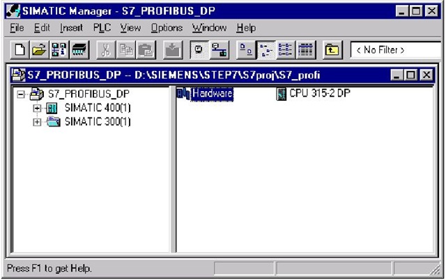
In the configuration process, the composition of the equipment is determined, the connection methods, the networks used, the addresses, the settings for the modules used are selected. The finished configuration is loaded into the PLC, which is also a hardware setup.

Configuration utilities allow you to diagnose hardware, detect hardware errors or improper installation.
PLC programming is also performed using Simatic Manager, which provides program writing in three editors:
I worked from the very beginning in STL, I tried LAD, it seemed to me too incomprehensible, and many things could not be done so easily in it, as in STL. The advantage is that when the program is loaded into the PLC, it is compiled into the STL and, accordingly, when it is downloaded from the PLC to the programmer, it is also represented in the STL.
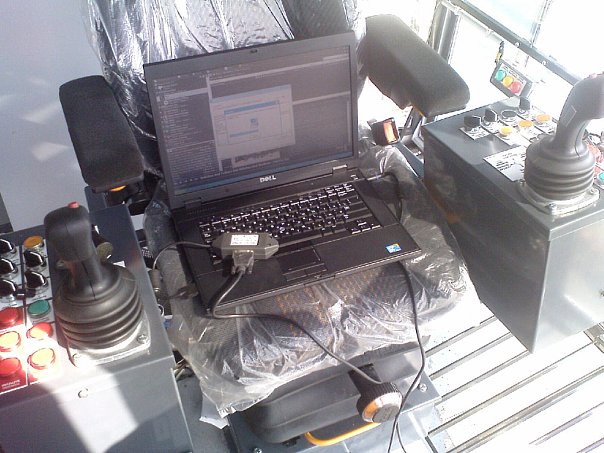
PLC programming is fascinating, especially when it’s not a stand, but real equipment.
My job was to create a program on the PLC to control the entire machine GP or its individual parts, as well as downloading the software directly into the equipment and debugging it.
Different things happened, but working with iron was very interesting, though not sometimes easy.
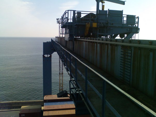
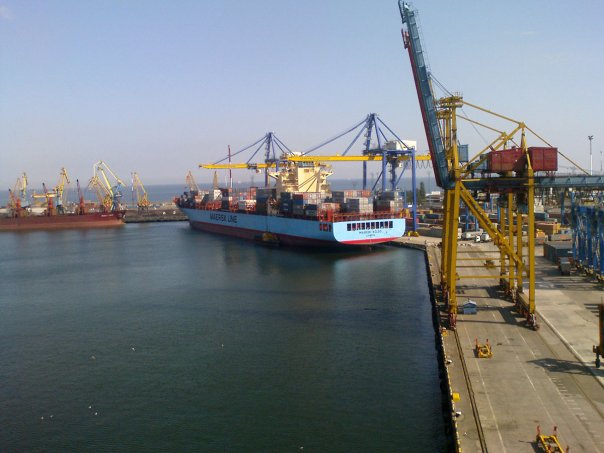
And we built such GP machines here:
This post contains general information about programming a Siemens PLC.
Introduction
I got a job in this company on the 5th year of the institute. By the way, my education is indirectly related to programming and it was more of a fad. My knowledge at that time was limited to the course of Delphi and a very basic Assembler. The company was engaged in (and is engaged in) the design, construction and maintenance of lifting equipment, such as loaders, gantries, gantries, bridge cranes and other cranes. For GP machines, my education had even less of a relationship. So I decided to try. :)
')
Siemens programmable logic controllers
Siemens PLCs are industrial controllers and are used to automate technological processes. We have, in particular, used to automate the work of lifting machines.
Simatic includes several PLC lines - Simatic S5 and Simatic S7. In turn, the Simatic S7 line contains the S7-200, S7-300, S7-400 and S7-1200 families.
Most often, we used PLCs of the S7-300 and S7-400 families , for which Siemens developed its own software, Simatic Step 7 .
PLCs included:
- central processing unit (CPU);
- power supplies (PS) to power the controller from an AC or DC network;
- signal modules (SM), intended for input / output of discrete and analog signals;
- communication processors (CP), performing autonomous processing of communication tasks in industrial networks Profibus, Industrial Ethernet, etc .;
- functional modules (FM), which performed the tasks of automatic control, weighing, positioning, etc .;
- interface modules (IM) for connecting expansion racks to the base unit of the controller.
In addition, a large number of slave devices, such as frequency converters, drives, absolute / incremental encoders, etc., were connected to the PLC via the Profibus network.
All the work of the machine GP was automated to the maximum and the crane operator needed to apply a minimum of effort to control it.
What is Simatic Step 7?
The main utility is Step 7 - Simatic Manager, which allows configuration of PLCs and networks (HWConfig and NetPro utilities).
In the configuration process, the composition of the equipment is determined, the connection methods, the networks used, the addresses, the settings for the modules used are selected. The finished configuration is loaded into the PLC, which is also a hardware setup.
Configuration utilities allow you to diagnose hardware, detect hardware errors or improper installation.
PLC programming is also performed using Simatic Manager, which provides program writing in three editors:
- LAD (Ladder Diagram) - ladder diagrams. The editor displays the program in a graphical representation, similar to an electrical wiring diagram. Logic circuits allow the program to simulate the flow of electric current from a voltage source through a series of logic conditions at the inputs, which activate the conditions at the outputs. The voltage source is the tire on the left.
The main elements are normally closed and normally open contacts.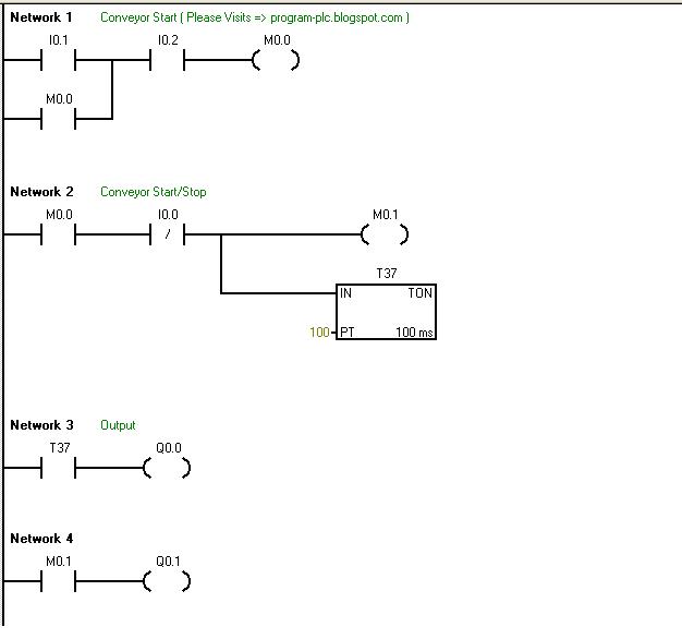
Accordingly, the closed contacts allow the flow of a signal to flow through them to the next element, the open contacts prevent flow of the signal.
The logic is divided into segments, so-called. nets (Network), the program is executed from left to right and from top to bottom.
The features of the LAD editor are ease of use and understanding for novice programmers. - FBD (Function Block Diagram) - functional block diagrams. This editor displays the program in the form of conventional logic circuits. There are no contacts, but there are equivalent functional blocks. This editor does not use the notion of “signal flow”, as in LAD, it is expressed in a similar notion of control flow through logical blocks FBD.

The signal flow is called state “1” through the FBD elements. The logic of the program derives from the connections between functional blocks denoting commands.
The graphical representation of the functional plan well reflects the process of program execution. - STL (Statement List) - a list of instructions. This editor allows you to create programs by entering the mnemonic notation for commands. In this editor, you can create programs that cannot be created in the LAD and FBD editors. Programming in STL is very similar to programming in Assembler, a bit specific.
The PLC executes the commands in the order determined by the program from top to bottom, then starts over.
With the help of the STL editor you can always view or edit programs created on the LAD or FBD, the reverse is not always possible.
I worked from the very beginning in STL, I tried LAD, it seemed to me too incomprehensible, and many things could not be done so easily in it, as in STL. The advantage is that when the program is loaded into the PLC, it is compiled into the STL and, accordingly, when it is downloaded from the PLC to the programmer, it is also represented in the STL.
Instead of conclusion
PLC programming is fascinating, especially when it’s not a stand, but real equipment.
My job was to create a program on the PLC to control the entire machine GP or its individual parts, as well as downloading the software directly into the equipment and debugging it.
Different things happened, but working with iron was very interesting, though not sometimes easy.
And we built such GP machines here:
Source: https://habr.com/ru/post/139180/
All Articles