Comparison of characteristics of micromechanical gyros
Recently I learned that STMicroelectronics announced the A3G4250D three-axis gyroscope, which meets the strict standard for automotive applications (AEC-Q100). Promised cost of $ 6 for orders of 1000 pcs. Price class is clear. I wanted to compare the passport characteristics of this sensor with venerable models from Analog Devices Inc. and other manufacturers. While I was dealing with datasheets, I found out that the set of ADI and STM passport specifications, for example, is not the same. Along the way, I decided to find out for some reason why parrots should compare sensors, what is the most serious problem of micromechanics. As a result, the material was collected for the post, and maybe two. This will be an introductory. Comparison a la "[30 kop. Bunch] Vs. [Pig-iron bridge]" unfortunately did not fit.
On the principles of operation of different classes of micromechanical gyroscopes and accelerometers, you can write more than one article. There are several separate types / classes of devices. If you do not go into details, roughly it can be said as follows.
The sensitive element (SE) of a micromechanical gyroscope is the inertial mass, which is fixed inside the body on the springs (elastic consoles of a semiconductor, etc.). This sensitive mass is driven into oscillatory motion along one of the sensor axes. This axis is the axis of excitation (input axis). On this axis, the operating mode is set. Measurements are made on an axis perpendicular to it (output). The principle of operation is that when the body rotates around its measuring axis (it is also called the axis of sensitivity), in addition to oscillations along the input axis, the sensitive element also oscillates along the third, output axis. If anyone knows what the Lissajous Shapes are , he will easily understand that the ChE begins to describe a circle (or ellipse) in space.
This is how the single-axis sensor works. In two and three-axis sensors, the complex of the sensing element and the measuring system is framed by another suspension / gauge system. Those. One ChE / Suspension / Gauge assembly (let it be an assembly for the X axis) is itself an oscillating ChE for another assembly (eg, according to OY), which is included in the OZ measurement assembly. A separate system is also possible.
A specialist in micromechanics in the text above can find enough flaws. Written roughly and for ease of perception. And it is written to smoothly go over to the description of one of the most serious problems of micromechanics, namely, sensitivity to linear accelerations.
In theory, an oscillating SE should not feel accelerations and should not have cross-links (in the case of two- or three-axis dats) with other axes of sensitivity (PTS). But due to the imperfect creation of a three-dimensional structure inside an integrated microcircuit, the centers of mass of the SCs are shifted, residual stresses appear in the material, the springs have different elasticities, etc. As a result, the CE for OX begins to react to the effects of OY, linear accelerations begin to distort the gyroscope readings. Those. in measurements, an increment in the angular velocity of which actually does not appear (random drift).
It is impossible (or not advisable) to make the production of sensitive elements ideal, therefore, additional elements appear in the sensor design that are needed to reduce sensitivity to the parasitic effects mentioned. First of all, cheap (up to $ 10-15) sensors from sensors of average ($ 30-100) and upper ($ 100 +) price ranges differ by simplicity and even by the presence of elements of rejection of parasitic effects.
In one of the habstats, I discussed the question of the negligence of the reaction of inexpensive gyros to parasitic effects ( for example, here ). It is clear that for a static quadcopter there is no need to bother. But this is only a demo device that will be used in statics. UAV should move, and have decent dynamic characteristics. Otherwise, why can it be used?For a look, and what's behind the fence?
About the reaction to vibrations that have high intensity in quadcopters, for example, it is not necessary to tell much. Everyone knows what it is. Therefore, I believe that the issue of the sensitivity of gyroscopes to acceleration and vibrations is very important for creating a moving object with normal dynamics.
The first thing that strikes developers in datasheets for sensors is the so-called "zero stability". After all, it seems that this parameter ultimately determines the sensitivity of the sensor, i.e. the minimum input that the sensor feels. So due to the low zero stability of many MMG models, many still believe that micromechanical gyroscopes (MMGs) do not feel the rotation of the Earth. There are MMG models with zero stability of just over 2 ° / hour (the Earth, as is known, rotates at a speed of 15 ° / hour). But in practice this does not mean that it will still be possible to measure the rotation of the Earth.
Be that as it may, the developer is looking at zero stability. This is a clear parameter that shows the extent to which the zero of the sensor scale will fluctuate in the laboratory. However, this is the stability parameter of the “spherical horse in vacuum”. In reality, the declared stability will not be. Why? Yes, because there is indicated stability (or rather instability) due to internal sources of error. In what conditions the sensor will work the manufacturer will not be able to predict, as well as the deviations caused by these conditions.
There are two approaches to dealing with inaccuracies: hardware and algorithmic (read software). The second approach implies the addition of special software modules for correcting errors caused by parasitic processes to the BTsEVM firmware. And this approach is not recommended as the best. First of all, the sensor itself must suppress noise. The central brain should be engaged not in cleaning out the main debris, but in finishing and calculating high-level algorithms (navigation, stabilization, automation). There are all sorts of methodological errors. They are easily described by some formulas, so they can be easily compensated programmatically.
Why all this? And besides, it is more correct to choose sensors that are optimal in terms of price-to-accuracy ratio. And here the main parameters of choice will most likely be the gyro sensitivity to linear acceleration (g sensitivity) and vibrations (g² sensitivity). Why they are main is explained below.
MMG have zero errors, which vary depending on the temperature inside the case. For temperature compensation, temperature sensors are built into the MMG. Their accuracy does not matter, only the repeatability of indications is important. But with thermal compensation there is a problem - hysteresis. In this case, the hysteresis is the difference between the required correction value for a specific temperature in two cases - when the device reaches this temperature by cooling and in the case when it heats up to the same temperature. See chart below.

This graph shows the zero temperature hysteresis for MMG ADXRS453 when the temperature varies from + 25 ° to + 130 ° , then to -45 ° and back to + 25 ° . This hysteresis occurs regardless of whether the sensor is turned on during temperature fluctuations or not. In addition, the hysteresis depends on how wide the range of temperature changes.
Is the situation difficult? Not, no so much. In general, MMG should not be used to determine the orientation angles in the absence of some external reference system, which allows you to reset the accumulated error to a low level. The current zero offset can be determined using the same system. Thus, the temperature zero offset and the error of the scale factor in normal use can be effectively compensated (albeit with an accuracy of some small, non-zero value).
')
As described above, spherical MMG in vacuum measures only rotation and nothing else. However, due to the asymmetry of the fine element and the non-ideal production, all MMGs feel accelerations. Sensitivity to acceleration is most often understood as sensitivity to linear acceleration (g-sensitivity) and to linear vibrations (g²-sensitivity). On objects moving in the field of the Earth, in any case, acceleration acts (except for cases of free fall). Sensitivity to linear accelerations is often the main source of error.
MMGs in the lowest price range are optimized primarily in terms of cost, but not in terms of resistance to vibrations. They have a relatively simple mechanical system. Although it is distinguished by its vitality (it withstands huge overloads of 10'000 g), it is not protected from vibrations. Low mass of the sensing element -> wide bandwidth. In such gyroscopes, the sensitivity to acceleration (acceleration effect in datasheets) can be equal to 1000 ° / h / g (or 0.3 ° / s / g). And this value is quite normal for this class of sensors. But it is an order of magnitude higher than should be expected from accurate sensors. From cheap sensors you should not expect zero stability in the context of acceleration sensitivity. Even small rotations in the field of the Earth lead to huge errors due to their extreme sensitivity to acceleration and vibrations. By the way, I did not find the “aceleration effect” in the datasheet for A3G4250D from STMicroelectronics. This parameter is not specified for this sensor class. He just means big. Below is a comparative table for some higher class MMG models.
This table contains sensors that are classified as accurate. And even for them, both parameters are not always specified by the manufacturer.
Often, compensation for accelerometer readings is used to compensate for sensitivity to acceleration. Below is an example from the comments about the use of an inertial navigation system (INS) with several sensors on the example of the problem of stabilizing the height of a quadrocopter on the topic of quadcopters:
But it turns out the drift due to sensitivity to acceleration depends on the frequency with which this acceleration varies. Below are graphs of the MMG CRG20-01 output signal (in piece deliveries in the form of a demo-board, if I am not mistaken, it costs around $ 100-150 with delivery) on the frequency of the applied acceleration.
The graph shows that the error does not depend on the amplitude of acceleration. But there is a dependence on frequency. And just so you will not compensate for this error (a large variation and a complex curve of sensitivity change). To compensate for g²-sensitivity, if it is constant, is easy. But again, not all manufacturers in the datasheets provide graphs for this parameter. A developer often has to build these graphs himself experimentally. And often this is done in the field on devices already in operation.
Another ambush with accelerometer correction is phase matching. In the general case, the natural frequencies of the accelerometer and the gyroscope do not coincide, and the frequency characteristics in general. Therefore, at different frequencies of vibrations, MMA and MMG will produce different phase shifts of the output signal relative to vibrations at the input. Ultimately, accelerometer correction may increase! error instead of extinguishing it. This will happen if the difference between the MMA and MMG phase shifts will approach the value of 3.14 radians (180 degrees).
In the end, because sensitivity to vibrations and accelerations varies greatly even within the same sensor model or it is too large, the manufacturer simply does not indicate it. True, it should be noted, in fact, it is rather difficult to test the sensors for sensitivity to vibrations. Problems are both technical and methodological.
To reduce the sensitivity to vibrations, you can, of course, mount the sensors through a rubber insulator. But to make it so that this suspension has a uniform distribution of characteristics for a wide range of frequencies, and even did not change them with aging, it is very difficult.
Below is a comparison of errors due to sensitivity to acceleration and vibrations when g-compensation is not used (in g / s).
And the following table shows the errors that remain even after the introduction of g-compensation (in g / s).

As we can see, even with the introduction of g-compensation, the error in sensitivity to acceleration may still be greater than the error due to temperature instability of zero (see the hysteresis graph above).
What was written above suggests that the most obvious parameter of accuracy is not always the main criterion for the choice of sensors. “It’s always dark under the candles,” proverb says. What is not clearly described in the datasheet or not specified at all can play a decisive role in the success of the project. You can focus on the stability of zero and the variance of noise, and in fact they can be defeated by simple algorithms (averaged over time or using redundant measuring units ). But the error due to vibrations, as we saw above using the example of CRG20-01, may be difficult to describe in the algorithm. For a long time, zero stability is the gold standard for choosing MMG. However, in practice, sensitivity to acceleration and vibration can have a greater impact on accuracy.
I wanted to make a post containing two parts - 1) Justification of the choice of the comparison criterion and 2) Comparison of the TTX models from Analog Devices Inc., Silicon Sensing, Sensonor and STMicroelectronics. However, it turned out "mnogabukv." If it is interesting, I will soon try to compare the sensors of the mentioned companies with datasheets with an explanation of the physical meaning of the main characteristics.
UPD: fixed some typos and grammatical errors.
Introduction
On the principles of operation of different classes of micromechanical gyroscopes and accelerometers, you can write more than one article. There are several separate types / classes of devices. If you do not go into details, roughly it can be said as follows.
The sensitive element (SE) of a micromechanical gyroscope is the inertial mass, which is fixed inside the body on the springs (elastic consoles of a semiconductor, etc.). This sensitive mass is driven into oscillatory motion along one of the sensor axes. This axis is the axis of excitation (input axis). On this axis, the operating mode is set. Measurements are made on an axis perpendicular to it (output). The principle of operation is that when the body rotates around its measuring axis (it is also called the axis of sensitivity), in addition to oscillations along the input axis, the sensitive element also oscillates along the third, output axis. If anyone knows what the Lissajous Shapes are , he will easily understand that the ChE begins to describe a circle (or ellipse) in space.
This is how the single-axis sensor works. In two and three-axis sensors, the complex of the sensing element and the measuring system is framed by another suspension / gauge system. Those. One ChE / Suspension / Gauge assembly (let it be an assembly for the X axis) is itself an oscillating ChE for another assembly (eg, according to OY), which is included in the OZ measurement assembly. A separate system is also possible.
A specialist in micromechanics in the text above can find enough flaws. Written roughly and for ease of perception. And it is written to smoothly go over to the description of one of the most serious problems of micromechanics, namely, sensitivity to linear accelerations.
In theory, an oscillating SE should not feel accelerations and should not have cross-links (in the case of two- or three-axis dats) with other axes of sensitivity (PTS). But due to the imperfect creation of a three-dimensional structure inside an integrated microcircuit, the centers of mass of the SCs are shifted, residual stresses appear in the material, the springs have different elasticities, etc. As a result, the CE for OX begins to react to the effects of OY, linear accelerations begin to distort the gyroscope readings. Those. in measurements, an increment in the angular velocity of which actually does not appear (random drift).
It is impossible (or not advisable) to make the production of sensitive elements ideal, therefore, additional elements appear in the sensor design that are needed to reduce sensitivity to the parasitic effects mentioned. First of all, cheap (up to $ 10-15) sensors from sensors of average ($ 30-100) and upper ($ 100 +) price ranges differ by simplicity and even by the presence of elements of rejection of parasitic effects.
In one of the habstats, I discussed the question of the negligence of the reaction of inexpensive gyros to parasitic effects ( for example, here ). It is clear that for a static quadcopter there is no need to bother. But this is only a demo device that will be used in statics. UAV should move, and have decent dynamic characteristics. Otherwise, why can it be used?
About the reaction to vibrations that have high intensity in quadcopters, for example, it is not necessary to tell much. Everyone knows what it is. Therefore, I believe that the issue of the sensitivity of gyroscopes to acceleration and vibrations is very important for creating a moving object with normal dynamics.
Errors of micromechanical gyros
The first thing that strikes developers in datasheets for sensors is the so-called "zero stability". After all, it seems that this parameter ultimately determines the sensitivity of the sensor, i.e. the minimum input that the sensor feels. So due to the low zero stability of many MMG models, many still believe that micromechanical gyroscopes (MMGs) do not feel the rotation of the Earth. There are MMG models with zero stability of just over 2 ° / hour (the Earth, as is known, rotates at a speed of 15 ° / hour). But in practice this does not mean that it will still be possible to measure the rotation of the Earth.
Be that as it may, the developer is looking at zero stability. This is a clear parameter that shows the extent to which the zero of the sensor scale will fluctuate in the laboratory. However, this is the stability parameter of the “spherical horse in vacuum”. In reality, the declared stability will not be. Why? Yes, because there is indicated stability (or rather instability) due to internal sources of error. In what conditions the sensor will work the manufacturer will not be able to predict, as well as the deviations caused by these conditions.
There are two approaches to dealing with inaccuracies: hardware and algorithmic (read software). The second approach implies the addition of special software modules for correcting errors caused by parasitic processes to the BTsEVM firmware. And this approach is not recommended as the best. First of all, the sensor itself must suppress noise. The central brain should be engaged not in cleaning out the main debris, but in finishing and calculating high-level algorithms (navigation, stabilization, automation). There are all sorts of methodological errors. They are easily described by some formulas, so they can be easily compensated programmatically.
Why all this? And besides, it is more correct to choose sensors that are optimal in terms of price-to-accuracy ratio. And here the main parameters of choice will most likely be the gyro sensitivity to linear acceleration (g sensitivity) and vibrations (g² sensitivity). Why they are main is explained below.
Temperature zero hysteresis
MMG have zero errors, which vary depending on the temperature inside the case. For temperature compensation, temperature sensors are built into the MMG. Their accuracy does not matter, only the repeatability of indications is important. But with thermal compensation there is a problem - hysteresis. In this case, the hysteresis is the difference between the required correction value for a specific temperature in two cases - when the device reaches this temperature by cooling and in the case when it heats up to the same temperature. See chart below.
This graph shows the zero temperature hysteresis for MMG ADXRS453 when the temperature varies from + 25 ° to + 130 ° , then to -45 ° and back to + 25 ° . This hysteresis occurs regardless of whether the sensor is turned on during temperature fluctuations or not. In addition, the hysteresis depends on how wide the range of temperature changes.
Is the situation difficult? Not, no so much. In general, MMG should not be used to determine the orientation angles in the absence of some external reference system, which allows you to reset the accumulated error to a low level. The current zero offset can be determined using the same system. Thus, the temperature zero offset and the error of the scale factor in normal use can be effectively compensated (albeit with an accuracy of some small, non-zero value).
')
Vibration errors
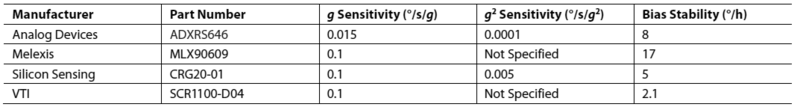
As described above, spherical MMG in vacuum measures only rotation and nothing else. However, due to the asymmetry of the fine element and the non-ideal production, all MMGs feel accelerations. Sensitivity to acceleration is most often understood as sensitivity to linear acceleration (g-sensitivity) and to linear vibrations (g²-sensitivity). On objects moving in the field of the Earth, in any case, acceleration acts (except for cases of free fall). Sensitivity to linear accelerations is often the main source of error.
MMGs in the lowest price range are optimized primarily in terms of cost, but not in terms of resistance to vibrations. They have a relatively simple mechanical system. Although it is distinguished by its vitality (it withstands huge overloads of 10'000 g), it is not protected from vibrations. Low mass of the sensing element -> wide bandwidth. In such gyroscopes, the sensitivity to acceleration (acceleration effect in datasheets) can be equal to 1000 ° / h / g (or 0.3 ° / s / g). And this value is quite normal for this class of sensors. But it is an order of magnitude higher than should be expected from accurate sensors. From cheap sensors you should not expect zero stability in the context of acceleration sensitivity. Even small rotations in the field of the Earth lead to huge errors due to their extreme sensitivity to acceleration and vibrations. By the way, I did not find the “aceleration effect” in the datasheet for A3G4250D from STMicroelectronics. This parameter is not specified for this sensor class. He just means big. Below is a comparative table for some higher class MMG models.
This table contains sensors that are classified as accurate. And even for them, both parameters are not always specified by the manufacturer.
Often, compensation for accelerometer readings is used to compensate for sensitivity to acceleration. Below is an example from the comments about the use of an inertial navigation system (INS) with several sensors on the example of the problem of stabilizing the height of a quadrocopter on the topic of quadcopters:
If the drift is constant and always in the same direction, it only means that the calibration is incorrect. In MultiWii 0, the weight is calibrated every time it is turned on, but not perfect (rounded to the whole) if you enter at least tenths it becomes much better. But in this application of the gyroscope, even a perceptible drift is not terrible, as there is a reference orientation (compass and accelerometer) for which it is corrected.
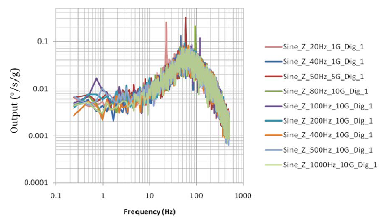
But it turns out the drift due to sensitivity to acceleration depends on the frequency with which this acceleration varies. Below are graphs of the MMG CRG20-01 output signal (in piece deliveries in the form of a demo-board, if I am not mistaken, it costs around $ 100-150 with delivery) on the frequency of the applied acceleration.
The graph shows that the error does not depend on the amplitude of acceleration. But there is a dependence on frequency. And just so you will not compensate for this error (a large variation and a complex curve of sensitivity change). To compensate for g²-sensitivity, if it is constant, is easy. But again, not all manufacturers in the datasheets provide graphs for this parameter. A developer often has to build these graphs himself experimentally. And often this is done in the field on devices already in operation.
Another ambush with accelerometer correction is phase matching. In the general case, the natural frequencies of the accelerometer and the gyroscope do not coincide, and the frequency characteristics in general. Therefore, at different frequencies of vibrations, MMA and MMG will produce different phase shifts of the output signal relative to vibrations at the input. Ultimately, accelerometer correction may increase! error instead of extinguishing it. This will happen if the difference between the MMA and MMG phase shifts will approach the value of 3.14 radians (180 degrees).
In the end, because sensitivity to vibrations and accelerations varies greatly even within the same sensor model or it is too large, the manufacturer simply does not indicate it. True, it should be noted, in fact, it is rather difficult to test the sensors for sensitivity to vibrations. Problems are both technical and methodological.
To reduce the sensitivity to vibrations, you can, of course, mount the sensors through a rubber insulator. But to make it so that this suspension has a uniform distribution of characteristics for a wide range of frequencies, and even did not change them with aging, it is very difficult.
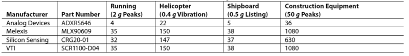
Below is a comparison of errors due to sensitivity to acceleration and vibrations when g-compensation is not used (in g / s).
And the following table shows the errors that remain even after the introduction of g-compensation (in g / s).
As we can see, even with the introduction of g-compensation, the error in sensitivity to acceleration may still be greater than the error due to temperature instability of zero (see the hysteresis graph above).
findings
What was written above suggests that the most obvious parameter of accuracy is not always the main criterion for the choice of sensors. “It’s always dark under the candles,” proverb says. What is not clearly described in the datasheet or not specified at all can play a decisive role in the success of the project. You can focus on the stability of zero and the variance of noise, and in fact they can be defeated by simple algorithms (averaged over time or using redundant measuring units ). But the error due to vibrations, as we saw above using the example of CRG20-01, may be difficult to describe in the algorithm. For a long time, zero stability is the gold standard for choosing MMG. However, in practice, sensitivity to acceleration and vibration can have a greater impact on accuracy.
Conclusion
I wanted to make a post containing two parts - 1) Justification of the choice of the comparison criterion and 2) Comparison of the TTX models from Analog Devices Inc., Silicon Sensing, Sensonor and STMicroelectronics. However, it turned out "mnogabukv." If it is interesting, I will soon try to compare the sensors of the mentioned companies with datasheets with an explanation of the physical meaning of the main characteristics.
UPD: fixed some typos and grammatical errors.
Source: https://habr.com/ru/post/139110/
All Articles