Haskell - Aesthetics
I invent a special game in the space simulator genre. According to one of the key concepts, the game will have a built-in programming language with which you can develop and improve algorithms for the interaction of game elements. The design of such a language is not easy, considering its “naturalness”, and not “textual”. That is, language constructs are expressed in the form of different graphic objects. Drawing sketches of his designs, I was suddenly distracted and instead of using the language for the game I began to invent a language to visualize the Haskell code. It turned out so interesting that I could not leave the sketches just paper drawings. In January 2012, I started writing a visualization server, and this is what happened ...
')
To visualize something, you first need to parse it into meaningful units, and then match them with graphic elements. In the case of code, such units will be syntactic elements of the language, so, in the first step, we need to parse the code into an abstract syntax tree (AST). The GHC compiler knows how to do it best, and there are even binders for it, which are what they do. Scion is a library that allows you to analyze code through the GHC API. Scion is used, for example, in EclipseFP for syntax highlighting and error analysis on the fly. And it would be good if it were not for its complexity, which was useless in the early stages of development. I did not want to write the parser manually. It is curious that there was another way, simple and at the same time sufficient: the Language.Haskell library.
The Language.Haskell.Parser module is a parser for pure, no extensions Haskell'98 code (well, almost no extensions). The “advanced” programs will not spoil them, but at the beginning, Haskell'98 will suffice for the eyes. As a guinea pig, I took the factorial calculation code:
Parsing and analyzing using a library is done elementary, here’s an example of a simple program:
The parseModule function has the following type:
where the first argument is the Haskell code, and the value of the HsModule type is returned. To work with the HsModule type, you need to connect the Language.Haskell.Syntax module. Its type structure fully describes a subset of Haskell'98 as an AST:
In the GraphServer project, I divided the AST tree into its components so that it was more convenient to work with it:
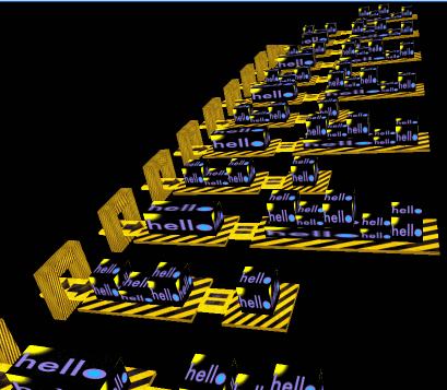
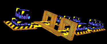
When the server will work as usual, it will be possible to send a string of Haskell code to it, which will be parsed by the server to AST and then rendered. Now, in the active phase of development, the server is idling. I simply select this or that “t-function” and start the whole process of visualization; but under the apparent simplicity of various mechanisms and algorithms are hidden, the result of which you can see in the picture:
Here are security expressions along with the right parts of the functions:
I wanted the graphical language to reflect the meaning of the syntax. Security expressions work as “execution filters”. We show the intuitiveness of the frame of thought experiment. Imagine that the execution flow is such a cube that can pass through the frame to the body of the function, or it can not pass, depending on its size (“logical condition”). The arrows in the picture above show the progress. What is fun, the frame, if you look at the scene from the front, turns into the very vertical line that we see in the code.
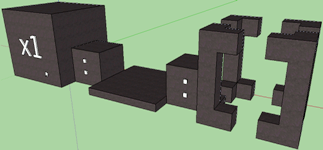
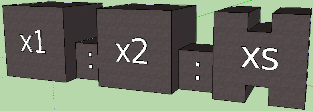
I tried to figure out how the list created by the operator would look: inside the pattern matching, and came so far to the variant in the pictures. The first corresponds to the expression (x1: x2: xs), the second to the expression (x1: _: []). Instead of the “unimportant” element, a flat platform is depicted, and the empty list is the empty one. The conditional if statement and the case construct are also somewhat intuitive. I have other draft sketches on paper, but much of the Haskell syntax still needs to be developed. This also applies to type declarations, and do-designs with its features, and pattern matching, and other important things. And then the created sketches need to be embodied in the code ...
So, there is a task: to generate graphic elements using syntax elements, somehow position and merge them into one scene, and then draw it. As we know, the process by which one language is transformed into another is called compilation. After several unsuccessful trials, I came to a phased compilation, in which the code does not turn into a mess, and it can be supplemented. Here are the steps:
I. Converting an AST Element to a StructureObject Element
Ii. Map primitive to the StructureObject element
Iii. Merge and position StructureObject relative to each other
Iv. Compiling graphics primitives into scene elements
V. Rendering (rendering) of the scene
Before we get to the implementation, consider the modules into which the server code is broken.
GraphServer (Main) - the main module of the program. Contains main function, server logic; it is the initialization of OpenGL, the creation of the window and the initial settings. In the same place lies the main program loop, and the draw function from the Draw.Draw module runs in it.
Common - common data and algorithms.
Common.Constants - common constants, settings, fixed data.
Common.GLTypes - OpenGL types (vectors, vertices, etc.), as well as other definitions.
Common.TestData - "t-functions", additional data for testing mechanisms.
Common.Units are functions for working with units of space, with OpenGL vectors and vertices.
Structure - data types and algorithms for compiling an AST tree into a StructureObject tree.
Structure.Constants - constants and settings associated with phases I, II, III.
Structure.StructureObject - the description of the central data type StructureObject.
Structure.GraphObject — The GraphObject type description and functions that create an object of this type.
Structure.Dimensions - working with dimensions of graphical objects.
Structure.SOConstruct - creating a StructureObject. Corresponds to stages I, II.
Structure.SOConnect - connecting multiple StructureObjects. Corresponds to stage III.
Structure.GOCompile - compilation of graphic primitives (GraphObject) into real objects of the scene. Corresponds to stage IV.
Structure.HsSyntaxTools - auxiliary functions for working with AST.
Structure.Texture - auxiliary data types and functions for working with textures.
Draw - functions that are responsible for rendering the scene.
Draw.Draw - contains the draw function, in which the scene is compiled and rendered.
Draw.GLInit - helper functions designed, as the name implies, to initialize OpenGL.
Draw.Render - contains the render function. Corresponds to stage V.
Draw.TextureInit - helper functions for creating textures.
Misc - other auxiliary functions.
Misc.BoxSide - functions from the HOpenGL library, in which the faces of the boxes are created.
ThirdParty - third-party utilities and programs.
ThirdParty.Frag - code from the program Frag. Download TGA files, create textures.
ThirdParty.GLUtil - additional utilities for working with OpenGL.
ThirdParty.ImageFormats - download TGA files.
I am testing and running algorithms in the draw function mentioned above:
The constructFramedGRhss and render functions do all the work, and at the output we get the pictures that are presented at the beginning of the article. The constructFramedGRhss function (and its analogues) from the Structure.SOConstruct module implements steps I - III. She has this type:
It accepts a certain ObjectConstruct-specification, and returns the finished hierarchy from StructureObject. The specification is just an ADT, where it is stated what syntactic unit we are dealing with:
The structureObject data type must be general enough to describe any possible hierarchical structure.
As you can see, the soStructureObjects field contains a list of child objects. In fact, the AST hierarchy is transformed into a StructureObject hierarchy with the accumulation of information necessary for rendering: position, size, graphic primitive, textures. The tree is built starting from the lowest levels, since it is the only way to determine where in the space the element of the overlying level should be located. This scheme imposes the restriction that it is impossible for the StructureObject objects to immediately assign absolute coordinates in the scene space: moving upward from the child objects, we cannot even imagine where the parent element will be. Thus, all StructureObjects can only be positioned relative to their parent object; that is, each StructureObject has its own offset in the OX, OY and OZ axes relative to the zero point of the parent. It looks like this:
The diagram conventionally depicts two StructureObjects: white panels correspond to the space of the parent object, brick panels correspond to the space of the child. By themselves, StructureObjects are not displayed on the scene, but are considered containers for graphic objects (blue in the diagram). Graphic objects are positioned relative to the zero point of the StructureObject containing them. Dimensions (dimensions) of the StructureObject are the common dimensions of all substructures and are needed for calculations in the parent element. The soGeometry field is of type Geometry. It contains the total displacement and dimensions given by a three-dimensional vector:
Similar data, as well as a graphic object, contains the field soGraphObjectSpec of the following type:
The creation code of the StructureObject is extensive and divided into two modules. Syntax elements, simple and complex, are converted to StructureObjects in the Structure.SOConstruct module. Initially, the translation offset in the soGeometry field is equal to the zero vector. We simply cannot know how the newly created StructureObject is located relative to the parent, and the parent does not even exist yet, nor does it necessarily appear in the future. The offset is reviewed later, in the code that the child creates for itself; or it simply remains zero, - then this object will be the guideline for its sub-objects. In the code below - the creation of three simple objects ("variable", "platform", "bridge") and one complex (infix operator with arguments):
Creating a complex object, we must somehow arrange its child objects. It is clear that for different syntactic units there will be different positions. We need to calculate and assign an offset to objects relative to zero. The parent, being a newly created object, will be shifted to zero (that is, not displaced at all), since we do not yet know how much to shift and what to do about it. Offsets are calculated by the connectStructureObjects function from the Structure.SOConnect module. The form of the syntactic unit and the list of sub-objects created earlier are transferred to it. For each case, the connectStructureObjects function has its own calculation options.
Imagine empty space, lined with coordinate axes. In the center of coordinates - zero. Mentally add a small box to the scene, shifted to the right-up. Now add a box of a different size, shifted to us and to the left. If both of these boxes are subobjects of a parent, then their edges limit its space. In the above scheme, the StructureObject is clearly visible: the object's space is determined by its contents. But how to calculate the total dimensions of the parent? We must take into account the displacement and size of each sub-element and find common minima, maxima of coordinates. Then the minima are subtracted from the highs, and the overall dimensions are obtained. We kind of draw the planes along the outermost edges of the objects, outlining the required space. This algorithm is well implemented by convolving a list of offsets and sizes, and the function is called generalizedDimension.
Despite the cumbersome functions in the modules Structure.SOConstruct and Structure.SOConnect, I haven’t yet come up with anything better. There is probably some kind of declarative solution, but it is unlikely that there will be less code. There are also special cases that are difficult to fit into a single declarative scheme; so, according to the design of the language, the function looks like a box of one unit in height, and its arguments are located on it. It follows that in order to calculate the length of the box, one must take into account the number of arguments, their sizes and the distance between them. The expression in the graphic language looks like a pyramid, which means that additional calculations arise associated with the protrusions of each underlying layer. Summarizing this task, I created a “mechanism of inherited dimensions”, in which derivedDimensions from the Structure.Dimensions module plays a key role. It accepts the original dimensions of the element, the sizes of the necessary children and the algorithm of inheritance, expressed as a higher order function, and returns new, "inherited" dimensions. The following is a simplified code from the constructExp function of a pre-previous listing:
Here, rawDim is the original size of the box for the variable, and dim is the new, “inherited” dimensions. The data constructor FuncDimensions belongs to a special data type DerivedDimensions:
The derivedDimensions function and higher order functions are defined as follows:
As you can see, for the FoundationDimensions constructor, the simplest algorithm is set in the derivedDimensions function, where the original dimensions are simply changed by a certain amount. The length and width increase by 2, and the height becomes 0.25. More complex cases are implemented using funcBoxDerivedDims and variableBoxDims. For example, the dim from that simplified code will become GL.Vector3 2 2 2, because the calculation will be reduced to calling variableBoxDims (GL.Vector3 1 2 2). If necessary, you can write other similar functions. For even more intuitiveness of the graphic language, I plan to add arity of functions in the future. It will look like the grooves on the box; empty grooves correspond to a curving or section. Of course, the mechanism of inherited dimensions alone will not be enough, because to determine arity we need more advanced code analysis than a simple decomposition into syntax. But that's another story…
Of great interest is the type of data GraphObject - primitive, template, blank, the prototype of the future element of the scene. At the initial stages of compilation, we do not need to know exactly the entire array of vertices of the primitive, it is easier to first set up some kind of blank, which then will be turned into real vertices, lines, faces. Thus, we abstract from the graphic representation and can modify it if necessary, or even replace it with something else.
It is easy to see that a StructureObject can have as many graphic objects (the GraphObjects constructor), and not even have them at all (the NoGraphObject constructor). And this is understandable: in the AST tree displayed above, there is nothing for the HsGuardedRhss value to match the graphical one. Rather, it will be a container for other objects, namely, for the right-hand parts of the function that contain guard expressions (Rhss - “right hand sides”). At the same time, “real” graphic objects are so far represented by only two elements: the primitive box PrimitiveBox and the advanced box TexturedBox. Both boxes have a value of the GLfVertex3 type - these are just the dimensions according to which six textured faces will be created at stage IV. The primitive box has one texture, and for TexturedBox it is possible to set a separate texture for each face. The ObjectTextureSpec type is designed like this:
Do you want the arrow to be on the top face, and all the others are textured by default? No problems!
Or just two faces with textures, and the rest - in some color? And it can.
Elements of type GraphObject are constructed using mnemonic functions during the creation of a StructureObject. Now in the Structure.GraphObject module there are the following functions: primitiveBox, variableBox, functionBox, foundationBox, arrowBridgeBox, equalSignBridgeBox, bridgeBox, and guardFrame. For example, here are just a few functions:
We should also tell about the rendering system. At the moment I compile graphic primitives in the objects of the scene and immediately draw them. This happens in the render function, which, as part of the draw function, is always spinning in the program loop. Of course, such code is inefficient, because when you compile the same StructureObject tree, you get the same scene with objects, and you could prepare it ahead of time. There are no obstacles here, besides rendering and compilation are easily separated if you return the list of actions [IO ()], and not to perform on the spot, as it is done now:
The rendering algorithm is recursive. Going down the tree from the root StructureObject, we expose all new and new offsets for the child elements, and when returning to the previous level, we remove these offsets. The compileGraphObjectSpec function compiles a GraphObject object into a scene object.The function sequence_ performs a list of actions [IO ()]. Graphic objects also have a relative offset, so we make analogous coordinate shifts:
In general, the code in the Structure.GOCompile module is very interesting for the techniques used (for example, convolutions and list comprehensions). Of course, such a code is harder to understand, but it seems to me that it has some kind of inner beauty and completeness, valuable in itself:
Boxes consist of faces, and faces are filled with color or texture. In OpenGL, any shape can be drawn vertically; in our case, these will be the vertices of the quadrilateral. The vertices are calculated from the length, height and width contained in dim, and the zero point corresponds to the corner of the box from left to bottom to back (simply because the axes in the OpenGL coordinate system are so directed: OX to the right, OY to up, OZ to us) . Faces are created in the Misc.BoxSide module using functions from the HOpenGL library.
Well, we rather superficially traced the general structure of the GraphServer program. I will not describe how the server part of the program is arranged, how pictures are loaded from files, how textures are created from pictures, how third-party utilities are used. There is still a lot of work, the visualization server is ready for 10 percent. The work is complicated by the fact that not all sketches are ready for all elements of Haskell. There are difficulties with visualization, which is very clearly seen in the screenshots; Still, debug textures are far from ideal. I would like to normalize the stretching of textures on an object, decorate it, create something more harmonious, and work on the design. Still need fonts and line drawing; in the future, analysis of functions on arity will be added, and this is another refactoring, other approaches, other methods. And again, it will require subtle techniques, tricky algorithms,smart data structures, which themselves are not easy to develop oh ... The project is large-scale, deep and bringing aesthetic pleasure. I invite everyone to join it: this is a practice in Haskell, and experience in designing large programs, and knowledge in graphics, and the study of algorithms. But above all, this art and creativity - that makes our lives more beautiful.
The code is open and located on GitHub: github.com/graninas/GraphServer
This is a cross article.On the design of the graphic language, read the article "Haskell - Design . "
PS Please readers: if you are interested in joining the project, contact me in a personal, in ICQ or by mail. Mail on Google, nickname is the same as on Habré. If you can, promote the article among other Haskell fans, or among those who would like to explore it by joining the project. Collective development will require some adaptation of the project and tools. I promise to approach the matter professionally.
')
To visualize something, you first need to parse it into meaningful units, and then match them with graphic elements. In the case of code, such units will be syntactic elements of the language, so, in the first step, we need to parse the code into an abstract syntax tree (AST). The GHC compiler knows how to do it best, and there are even binders for it, which are what they do. Scion is a library that allows you to analyze code through the GHC API. Scion is used, for example, in EclipseFP for syntax highlighting and error analysis on the fly. And it would be good if it were not for its complexity, which was useless in the early stages of development. I did not want to write the parser manually. It is curious that there was another way, simple and at the same time sufficient: the Language.Haskell library.
The Language.Haskell.Parser module is a parser for pure, no extensions Haskell'98 code (well, almost no extensions). The “advanced” programs will not spoil them, but at the beginning, Haskell'98 will suffice for the eyes. As a guinea pig, I took the factorial calculation code:
fact 'n | n == 0 = 1
| otherwise = fact ' ( n - 1 ) * n
Parsing and analyzing using a library is done elementary, here’s an example of a simple program:
import language . Haskell . Parser
main = do
s <- readFile "Fact.hs"
let parsed = parseModule s
putStrLn . show $ parsed
The parseModule function has the following type:
parseModule :: String -> ParseResult HsModule
where the first argument is the Haskell code, and the value of the HsModule type is returned. To work with the HsModule type, you need to connect the Language.Haskell.Syntax module. Its type structure fully describes a subset of Haskell'98 as an AST:
ParseOk
( HsModule
( SrcLoc { srcFilename = "<unknown>" , srcLine = 3 , srcColumn = 1 } )
( Module "Main" )
( Just [ HsEVar ( UnQual ( HsIdent "main" ) ) ] )
[ ]
[ HsFunBind
[ HsMatch
( SrcLoc { srcFilename = "<unknown>" , srcLine = 3 , srcColumn = 1 } )
( HsIdent "fact '" )
[ HsPVar ( HsIdent "n" ) ]
( HsGuardedRhss
[ HsGuardedRhs
( SrcLoc { srcFilename = "<unknown>" , srcLine = 3 , srcColumn = 9 } )
( HsInfixApp
( HsVar ( UnQual ( HsIdent "n" ) ) )
( HsQVarOp ( UnQual ( HsSymbol "==" ) ) )
( HsLit ( HsInt 0 ) ) )
( HsLit ( HsInt 1 ) )
, HsGuardedRhs
( SrcLoc { srcFilename = "<unknown>" , srcLine = 4 , srcColumn = 9 } )
( HsVar ( UnQual ( HsIdent "otherwise" ) ) )
( HsInfixApp
( HsApp
( HsVar ( UnQual ( HsIdent "fact '" ) ) )
( HsParen
( HsInfixApp
( HsVar ( UnQual ( HsIdent "n" ) ) )
( HsQVarOp ( UnQual ( HsSymbol "-" ) ) )
( HsLit ( HsInt 1 ) ) ) ) )
( HsQVarOp ( UnQual ( HsSymbol "*" ) ) )
( HsVar ( UnQual ( HsIdent "n" ) ) ) ) ] ) [ ] ] ] )
In the GraphServer project, I divided the AST tree into its components so that it was more convenient to work with it:
t1 = HsInfixApp ( HsVar ( UnQual ( HsIdent "n" ) ) )
( HsQVarOp ( UnQual ( HsSymbol "-" ) ) )
( HsLit ( HsInt 1 ) )
t2 = HsApp ( HsVar ( UnQual ( HsIdent "fact '" ) ) )
( HsParen t1 )
t3 = HsInfixApp t2
( HsQVarOp ( UnQual ( HsSymbol "*" ) ) )
( HsVar ( UnQual ( HsIdent "n" ) ) )
t4 = HsGuardedRhs ( SrcLoc { srcFilename = "<unknown>" , srcLine = 4 , srcColumn = 9 } )
( HsVar ( UnQual ( HsIdent "otherwise" ) ) )
t3
...
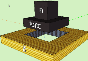
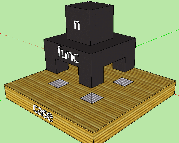
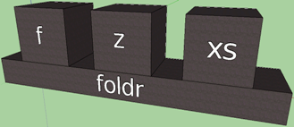
When the server will work as usual, it will be possible to send a string of Haskell code to it, which will be parsed by the server to AST and then rendered. Now, in the active phase of development, the server is idling. I simply select this or that “t-function” and start the whole process of visualization; but under the apparent simplicity of various mechanisms and algorithms are hidden, the result of which you can see in the picture:
Here are security expressions along with the right parts of the functions:
| n == 0 = 1
| otherwise = fact ' ( n - 1 ) * n
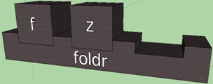
I wanted the graphical language to reflect the meaning of the syntax. Security expressions work as “execution filters”. We show the intuitiveness of the frame of thought experiment. Imagine that the execution flow is such a cube that can pass through the frame to the body of the function, or it can not pass, depending on its size (“logical condition”). The arrows in the picture above show the progress. What is fun, the frame, if you look at the scene from the front, turns into the very vertical line that we see in the code.
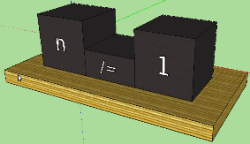
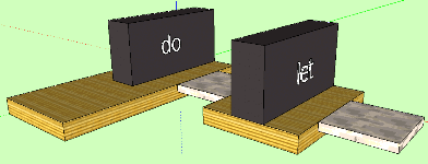
I tried to figure out how the list created by the operator would look: inside the pattern matching, and came so far to the variant in the pictures. The first corresponds to the expression (x1: x2: xs), the second to the expression (x1: _: []). Instead of the “unimportant” element, a flat platform is depicted, and the empty list is the empty one. The conditional if statement and the case construct are also somewhat intuitive. I have other draft sketches on paper, but much of the Haskell syntax still needs to be developed. This also applies to type declarations, and do-designs with its features, and pattern matching, and other important things. And then the created sketches need to be embodied in the code ...
So, there is a task: to generate graphic elements using syntax elements, somehow position and merge them into one scene, and then draw it. As we know, the process by which one language is transformed into another is called compilation. After several unsuccessful trials, I came to a phased compilation, in which the code does not turn into a mess, and it can be supplemented. Here are the steps:
I. Converting an AST Element to a StructureObject Element
Ii. Map primitive to the StructureObject element
Iii. Merge and position StructureObject relative to each other
Iv. Compiling graphics primitives into scene elements
V. Rendering (rendering) of the scene
Before we get to the implementation, consider the modules into which the server code is broken.
GraphServer (Main) - the main module of the program. Contains main function, server logic; it is the initialization of OpenGL, the creation of the window and the initial settings. In the same place lies the main program loop, and the draw function from the Draw.Draw module runs in it.
Common - common data and algorithms.
Common.Constants - common constants, settings, fixed data.
Common.GLTypes - OpenGL types (vectors, vertices, etc.), as well as other definitions.
Common.TestData - "t-functions", additional data for testing mechanisms.
Common.Units are functions for working with units of space, with OpenGL vectors and vertices.
Structure - data types and algorithms for compiling an AST tree into a StructureObject tree.
Structure.Constants - constants and settings associated with phases I, II, III.
Structure.StructureObject - the description of the central data type StructureObject.
Structure.GraphObject — The GraphObject type description and functions that create an object of this type.
Structure.Dimensions - working with dimensions of graphical objects.
Structure.SOConstruct - creating a StructureObject. Corresponds to stages I, II.
Structure.SOConnect - connecting multiple StructureObjects. Corresponds to stage III.
Structure.GOCompile - compilation of graphic primitives (GraphObject) into real objects of the scene. Corresponds to stage IV.
Structure.HsSyntaxTools - auxiliary functions for working with AST.
Structure.Texture - auxiliary data types and functions for working with textures.
Draw - functions that are responsible for rendering the scene.
Draw.Draw - contains the draw function, in which the scene is compiled and rendered.
Draw.GLInit - helper functions designed, as the name implies, to initialize OpenGL.
Draw.Render - contains the render function. Corresponds to stage V.
Draw.TextureInit - helper functions for creating textures.
Misc - other auxiliary functions.
Misc.BoxSide - functions from the HOpenGL library, in which the faces of the boxes are created.
ThirdParty - third-party utilities and programs.
ThirdParty.Frag - code from the program Frag. Download TGA files, create textures.
ThirdParty.GLUtil - additional utilities for working with OpenGL.
ThirdParty.ImageFormats - download TGA files.
I am testing and running algorithms in the draw function mentioned above:
draw :: DrawFunction
draw GLResources texRes n = do
putStr $ "Current n =" ++ show n
GL . clear [ GL . ColorBuffer , GL . DepthBuffer ]
GL . loadIdentity
GL . rotate 10 ( vector3 0 1 0 )
GL . rotate 20 ( vector3 1 0 0 )
GL . translate ( vector3 ( - 5 ) ( - 10 ) ( - 30 ) )
- Construct a hierarchy from StructureObject
let c = constructFramedGRhss ( OcsGuardedRhss t6 )
- Compile scene elements from graphic primitives
- and draw a scene
render texRes c
putStrLn "Ok."
The constructFramedGRhss and render functions do all the work, and at the output we get the pictures that are presented at the beginning of the article. The constructFramedGRhss function (and its analogues) from the Structure.SOConstruct module implements steps I - III. She has this type:
constructFramedGRhss :: ObjectConstructSpec -> StructureObject
It accepts a certain ObjectConstruct-specification, and returns the finished hierarchy from StructureObject. The specification is just an ADT, where it is stated what syntactic unit we are dealing with:
- Structure.StructureObject Module
data ObjectConstructSpec
= OcsApp HsExp
| OcsExpArgument HsExp
| OcsExpFuncName HsExp StructureObject
| OcsInfixOperator HsQOp
| OcsGuardedRhs HsGuardedRhs
| OcsFoundationExp StructureObject
| OcsGuardedRhss HsRhs
| OcsArrowBridge
| OcsEqualSignBridge
| OcsMatch HsMatch
The structureObject data type must be general enough to describe any possible hierarchical structure.
- Structure.StructureObject Module
data StructureObject = StructureObject
{ soObjectSpec :: ObjectSpec
, soGeometry :: Geometry
, soGraphObjectSpec :: GraphObjectSpec
, soStructureObjects :: StructureObjects
} deriving ( Show )
type StructureObjects = [ StructureObject ]
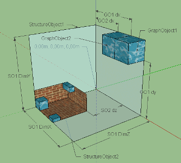
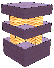
As you can see, the soStructureObjects field contains a list of child objects. In fact, the AST hierarchy is transformed into a StructureObject hierarchy with the accumulation of information necessary for rendering: position, size, graphic primitive, textures. The tree is built starting from the lowest levels, since it is the only way to determine where in the space the element of the overlying level should be located. This scheme imposes the restriction that it is impossible for the StructureObject objects to immediately assign absolute coordinates in the scene space: moving upward from the child objects, we cannot even imagine where the parent element will be. Thus, all StructureObjects can only be positioned relative to their parent object; that is, each StructureObject has its own offset in the OX, OY and OZ axes relative to the zero point of the parent. It looks like this:
The diagram conventionally depicts two StructureObjects: white panels correspond to the space of the parent object, brick panels correspond to the space of the child. By themselves, StructureObjects are not displayed on the scene, but are considered containers for graphic objects (blue in the diagram). Graphic objects are positioned relative to the zero point of the StructureObject containing them. Dimensions (dimensions) of the StructureObject are the common dimensions of all substructures and are needed for calculations in the parent element. The soGeometry field is of type Geometry. It contains the total displacement and dimensions given by a three-dimensional vector:
- Common.GLTypes module
type Geometry = ( Translation , Dimension )
type GLfVector3 = GL . Vector3 GL . GLfloat
type Translation = GLfVector3
type Dimension = GLfVector3
Similar data, as well as a graphic object, contains the field soGraphObjectSpec of the following type:
type GraphObjectSpec = ( Translation , Dimension , GraphObject )
The creation code of the StructureObject is extensive and divided into two modules. Syntax elements, simple and complex, are converted to StructureObjects in the Structure.SOConstruct module. Initially, the translation offset in the soGeometry field is equal to the zero vector. We simply cannot know how the newly created StructureObject is located relative to the parent, and the parent does not even exist yet, nor does it necessarily appear in the future. The offset is reviewed later, in the code that the child creates for itself; or it simply remains zero, - then this object will be the guideline for its sub-objects. In the code below - the creation of three simple objects ("variable", "platform", "bridge") and one complex (infix operator with arguments):
- Constructs an object for variable expression:
constructExp ( OcsExpArgument ( HsVar var ) ) = let
varText = makeName . getHsQualName $ var
rawDim = GL . Vector3 ( hsNameLength varText ) 2 2
dim = derivedDimensions ( FuncDimensions variableBoxDims ) rawDim
graphObjSpec = variableBox varText dim
in StructureObject OsArgument ( nullVector3 , dim ) graphObjSpec [ ]
- Designed "platform":
constructFoundation :: ObjectConstructSpec -> StructureObject
constructFoundation ( OcsFoundationExp expSo ) = let
expSoDim = geometryDim . soGeometry $ expSo
dim = derivedDimensions FoundationDimensions expSoDim
graphObjSpec = foundationBox dim
in StructureObject OsFoundation ( nullVector3 , dim ) graphObjSpec [ ]
- Constructed "bridge":
constructBridge :: ObjectConstructSpec -> StructureObject
constructBridge ocsBridgeType = let
dim = vector3 2 0.25 2
( graphObjSpec , bType ) = case ocsBridgeType of
OcsArrowBridge -> ( arrowBridgeBox dim , OsArrowBridge )
OcsEqualSignBridge -> ( equalSignBridgeBox dim , OsEqualSignBridge )
in StructureObject bType ( nullVector3 , dim ) graphObjSpec [ ]
- A complex object is constructed - an infix operator with arguments:
constructExp ( OcsExpArgument ( HsInfixApp exp1 qOp exp2 ) ) = let
exp1So = constructExp ( OcsExpArgument exp1 )
qOpSo = constructQOp ( OcsInfixOperator qOp )
exp2So = constructExp ( OcsExpArgument exp2 )
in connectStructureObjects OsInfixApp [ exp1So , qOpSo , exp2So ]
Creating a complex object, we must somehow arrange its child objects. It is clear that for different syntactic units there will be different positions. We need to calculate and assign an offset to objects relative to zero. The parent, being a newly created object, will be shifted to zero (that is, not displaced at all), since we do not yet know how much to shift and what to do about it. Offsets are calculated by the connectStructureObjects function from the Structure.SOConnect module. The form of the syntactic unit and the list of sub-objects created earlier are transferred to it. For each case, the connectStructureObjects function has its own calculation options.
connectStructureObjects :: ObjectSpec -> StructureObjects -> StructureObject
- Connect infix operator and two expressions:
connectStructureObjects OsInfixApp ( exp1So: opSo: exp2So: [ ] ) = let
exp1SoDim @ ( GL . Vector3 e1dl e1dh e1dw ) = geometryDim . soGeometry $ exp1So
exp2SoDim = geometryDim . soGeometry $ exp2So
opSoDim @ ( GL . Vector3 opdl opdh opdw ) = geometryDim . soGeometry $ opSo
exp1Trans = nullVector3 - Expression 1 starts at parent zero
opTrans = vector3 e1dl 0 0 - The operator is shifted along OX by the length of expression 1 (located next to it)
exp2Trans = vector3 ( e1dl + opdl ) 0 0 - Expression 2 is shifted by OY by the length of expression 1 and the length of the operator
generalDim = generalizedDimension [ ( exp1Trans , exp1SoDim ) - Overall dimensions of the parent
, ( exp2Trans , exp2SoDim )
, ( opTrans , opSoDim ) ]
newOpGoSpec = ( opTrans , opSoDim , graphObjectFromSpec . soGraphObjectSpec $ opSo )
newExp1So = exp1So { soGeometry = ( exp1Trans , exp1SoDim ) }
newExp2So = exp2So { soGeometry = ( exp2Trans , exp2SoDim ) }
in StructureObject OsInfixApp ( nullVector3 , generalDim ) newOpGoSpec [ newExp1So , newExp2So ]
Imagine empty space, lined with coordinate axes. In the center of coordinates - zero. Mentally add a small box to the scene, shifted to the right-up. Now add a box of a different size, shifted to us and to the left. If both of these boxes are subobjects of a parent, then their edges limit its space. In the above scheme, the StructureObject is clearly visible: the object's space is determined by its contents. But how to calculate the total dimensions of the parent? We must take into account the displacement and size of each sub-element and find common minima, maxima of coordinates. Then the minima are subtracted from the highs, and the overall dimensions are obtained. We kind of draw the planes along the outermost edges of the objects, outlining the required space. This algorithm is well implemented by convolving a list of offsets and sizes, and the function is called generalizedDimension.
- Structure.Dimensions module
generalizedDimension :: Geometries -> Dimension
generalizedDimension ( g: gs ) = toDimension ( foldr f g gs )
where
f ( ( GL . Vector3 dx1 dy1 dz1 ) , ( GL . Vector3 ax1 ay1 az1 ) )
( ( GL . Vector3 dx2 dy2 dz2 ) , ( GL . Vector3 ax2 ay2 az2 ) ) =
( vector3 ( min dx1 dx2 ) ( min dy1 dy2 ) ( min dz1 dz2 ) ,
vector3 ( max ( dx1 + ax1 ) ( dx2 + ax2 ) )
( max ( dy1 + ay1 ) ( dy2 + ay2 ) )
( max ( dz1 + az1 ) ( dz2 + az2 ) ) )
toDimension ( ( GL . Vector3 x1 y1 z1 ) , ( GL . Vector3 x2 y2 z2 ) ) =
vector3 ( abs ( x2 - x1 ) ) ( abs ( y2 - y1 ) ) ( abs ( z2 - z1 ) )
Despite the cumbersome functions in the modules Structure.SOConstruct and Structure.SOConnect, I haven’t yet come up with anything better. There is probably some kind of declarative solution, but it is unlikely that there will be less code. There are also special cases that are difficult to fit into a single declarative scheme; so, according to the design of the language, the function looks like a box of one unit in height, and its arguments are located on it. It follows that in order to calculate the length of the box, one must take into account the number of arguments, their sizes and the distance between them. The expression in the graphic language looks like a pyramid, which means that additional calculations arise associated with the protrusions of each underlying layer. Summarizing this task, I created a “mechanism of inherited dimensions”, in which derivedDimensions from the Structure.Dimensions module plays a key role. It accepts the original dimensions of the element, the sizes of the necessary children and the algorithm of inheritance, expressed as a higher order function, and returns new, "inherited" dimensions. The following is a simplified code from the constructExp function of a pre-previous listing:
let
rawDim = GL . Vector3 1 2 2
dim = derivedDimensions ( FuncDimensions variableBoxDims ) rawDim
...
Here, rawDim is the original size of the box for the variable, and dim is the new, “inherited” dimensions. The data constructor FuncDimensions belongs to a special data type DerivedDimensions:
- Structure.Dimensions module
data DerivedDimensions = FuncDimensions ( GLfVector3 -> GLfVector3 )
| FoundationDimensions
The derivedDimensions function and higher order functions are defined as follows:
- Structure.Dimensions module
derivedDimensions :: DerivedDimensions -> GLfVector3 -> GLfVector3
derivedDimensions ( FuncDimensions f ) dim = f dim
derivedDimensions FoundationDimensions ( GL . Vector3 l h w ) = vector3 ( l + 2 ) 0.25 ( w + 2 )
- Functions to place into DerivedDimensions
- | | Calculate function box dimensions according to dims
funcBoxDerivedDims :: GLfVector3 -> GLfVector3 -> GLfVector3
funcBoxDerivedDims ( GL . Vector3 opl oph opw ) ( GL . Vector3 fBoxl fBoxh fBoxw ) =
( GL . Vector3 ( f opl fBoxh ) fBoxh ( max opw fBoxw ) )
where
f op box | op > = box = op + 1
| ( box - op ) < 1 = op + 1
| ( box - op ) > = 1 = box
- | | Calculate dims for variable box
variableBoxDims :: GLfVector3 -> GLfVector3
variableBoxDims ( GL . Vector3 varl varh varw ) =
( GL . Vector3 ( if varl < 2 then 2 else varl ) varh varw )
As you can see, for the FoundationDimensions constructor, the simplest algorithm is set in the derivedDimensions function, where the original dimensions are simply changed by a certain amount. The length and width increase by 2, and the height becomes 0.25. More complex cases are implemented using funcBoxDerivedDims and variableBoxDims. For example, the dim from that simplified code will become GL.Vector3 2 2 2, because the calculation will be reduced to calling variableBoxDims (GL.Vector3 1 2 2). If necessary, you can write other similar functions. For even more intuitiveness of the graphic language, I plan to add arity of functions in the future. It will look like the grooves on the box; empty grooves correspond to a curving or section. Of course, the mechanism of inherited dimensions alone will not be enough, because to determine arity we need more advanced code analysis than a simple decomposition into syntax. But that's another story…
Of great interest is the type of data GraphObject - primitive, template, blank, the prototype of the future element of the scene. At the initial stages of compilation, we do not need to know exactly the entire array of vertices of the primitive, it is easier to first set up some kind of blank, which then will be turned into real vertices, lines, faces. Thus, we abstract from the graphic representation and can modify it if necessary, or even replace it with something else.
- Structure.GraphObjec Module
data GraphObject = NoGraphObject
| PrimitiveBox GLfVertex3 TextureName
| TexturedBox GLfVertex3 ObjectTextureSpec
| GraphObjects [ GraphObjectSpec ]
deriving ( Show )
It is easy to see that a StructureObject can have as many graphic objects (the GraphObjects constructor), and not even have them at all (the NoGraphObject constructor). And this is understandable: in the AST tree displayed above, there is nothing for the HsGuardedRhss value to match the graphical one. Rather, it will be a container for other objects, namely, for the right-hand parts of the function that contain guard expressions (Rhss - “right hand sides”). At the same time, “real” graphic objects are so far represented by only two elements: the primitive box PrimitiveBox and the advanced box TexturedBox. Both boxes have a value of the GLfVertex3 type - these are just the dimensions according to which six textured faces will be created at stage IV. The primitive box has one texture, and for TexturedBox it is possible to set a separate texture for each face. The ObjectTextureSpec type is designed like this:
- Structure.Texture Module
data ObjectTextureSpec = BoxTextureSpec
{ quadSideTexes :: [ ( BoxSide , QuadColorSpec ) ]
, defQuadSideTex :: QuadColorSpec
} deriving ( Show )
data QuadColorSpec = QuadTexture TextureName
| QuadPlainColor GLfColor4
| NoQuadColorSpec
deriving ( Show )
- The BoxSide type is described in the Common.GLTypes module.
- It is easy to guess what he is:
data BoxSide = SideTop
| Sidebottom
| Sideleft
| Sidelight
| Sidereear
| Sidefront
deriving ( Show , Eq )
Do you want the arrow to be on the top face, and all the others are textured by default? No problems!
let texes = [ ( SideTop , QuadTexture arrowTex ) ]
defaultTex = QuadTexture yellowBaseTex
boxTexSpec = BoxTextureSpec texes defaultTex
Or just two faces with textures, and the rest - in some color? And it can.
let texes = [ ( SideFront , QuadTexture arrowTex )
, ( SideRear , QuadTexture arrowTex ) ]]
defaultTex = QuadPlainColor ( color3 1 0 0 )
boxTexSpec = BoxTextureSpec texes defaultTex
Elements of type GraphObject are constructed using mnemonic functions during the creation of a StructureObject. Now in the Structure.GraphObject module there are the following functions: primitiveBox, variableBox, functionBox, foundationBox, arrowBridgeBox, equalSignBridgeBox, bridgeBox, and guardFrame. For example, here are just a few functions:
- Structure.GraphObject Module
primitiveBox trans dim @ ( GL . Vector3 l h w ) texName = ( trans , dim , PrimitiveBox ( vertex3 l h w ) texName )
variableBox _ dim @ ( GL . Vector3 l h w ) = ( nullVector3 , dim , PrimitiveBox ( vertex3 l h w ) helloTex )
arrowBridgeBox dim = bridgeBox dim arrowTex
equalSignBridgeBox dim = bridgeBox dim equalSignTex
bridgeBox dim @ ( GL . Vector3 l h w ) texName =
( nullVector3 , dim , TexturedBox ( vertex3 lh w ) boxTexSpec )
where
boxTexSpec = BoxTextureSpec texes defTex
texes = [ ( SideTop , QuadTexture texName ) ]
defTex = QuadTexture yellowBaseTex
We should also tell about the rendering system. At the moment I compile graphic primitives in the objects of the scene and immediately draw them. This happens in the render function, which, as part of the draw function, is always spinning in the program loop. Of course, such code is inefficient, because when you compile the same StructureObject tree, you get the same scene with objects, and you could prepare it ahead of time. There are no obstacles here, besides rendering and compilation are easily separated if you return the list of actions [IO ()], and not to perform on the spot, as it is done now:
- Draw.Render module
render texRes ( StructureObject _ ( soTrans , _ ) goSpec objects ) = do
GL . translate soTrans - set relative offset
mapM_ ( render texRes ) objects - recursively descend the tree
sequence_ $ compileGraphObjectSpec texRes goSpec - compile primitives and execute OpenGL calls
GL . translate negateVector3 $ soTrans - remove the relative offset
The rendering algorithm is recursive. Going down the tree from the root StructureObject, we expose all new and new offsets for the child elements, and when returning to the previous level, we remove these offsets. The compileGraphObjectSpec function compiles a GraphObject object into a scene object.The function sequence_ performs a list of actions [IO ()]. Graphic objects also have a relative offset, so we make analogous coordinate shifts:
- Structure.GOCompile module
compileGraphObjectSpec texRes ( goTrans , _, go ) = let
forwardTrans = GL . translate goTrans
compiled = compileGraphObject texRes go
backwardTrans = GL . google translate and . negateVector3 $ goTrans
in ( forwardTrans: compiled ) ++ [ backwardTrans ]
In general, the code in the Structure.GOCompile module is very interesting for the techniques used (for example, convolutions and list comprehensions). Of course, such a code is harder to understand, but it seems to me that it has some kind of inner beauty and completeness, valuable in itself:
- | | Box side drawings.
- | | It should be used only in this module.
f :: PreparedTextureObjects
-> GLfVertex3
-> ( BoxSide , QuadColorSpec )
-> ( [ BoxSide ] , [ IO ( ) ] )
-> ( [ BoxSide ] , [ IO ( ) ] )
f texRes boxDim ( side , qColorSpec ) ( sList , ioList ) = let
boxIO = do setQuadColorSpec texRes qColorSpec
GL . renderPrimitive GL . Quads ( boxSide boxDim side )
in ( side: sList , boxIO: ioList )
- | | Compiles GraphObject into action list structure, which is ready-to-eval. ([IO ()])
compileGraphObject :: PreparedTextureObjects -> GraphObject -> [ IO ( ) ]
compileGraphObject _ NoGraphObject = [ ]
compileGraphObject texRes ( GraphObjects gObjectSpecs ) =
concatMap ( compileGraphObjectSpec texRes ) gObjectSpecs
compileGraphObject texRes ( PrimitiveBox boxDim texName ) =
[ do GL . color colorWhite
GL . textureBinding GL . Texture2D GL .$= lookup texName texRes
GL . renderPrimitive GL . Quads ( allBoxSides boxDim ) ]
compileGraphObject texRes ( TexturedBox boxDim boxTexSpec ) = let
( BoxTextureSpec sideTexes defTex ) = boxTexSpec
( textedSides , textedSideDrawList ) = foldr ( f texRes boxDim ) ( [ ] , [ ] ) sideTexes
untextedSides = [ s | s <- boxSideList , s ` notElem`textedSides ]
untextedQColor = setQuadColorSpec texRes defTex
untextedSidesDraw = GL . renderPrimitive GL .Quads ( boxSides boxDim untextedSides )
in untextedQColor: untextedSidesDraw: textedSideDrawList
Boxes consist of faces, and faces are filled with color or texture. In OpenGL, any shape can be drawn vertically; in our case, these will be the vertices of the quadrilateral. The vertices are calculated from the length, height and width contained in dim, and the zero point corresponds to the corner of the box from left to bottom to back (simply because the axes in the OpenGL coordinate system are so directed: OX to the right, OY to up, OZ to us) . Faces are created in the Misc.BoxSide module using functions from the HOpenGL library.
boxSide :: GLfVertex3 -> BoxSide -> IO ( )
boxSide ( GL . Vertex3 x y z ) SideTop = do
GL . texCoord texCoordDR >> GL . vertex ( vertex3 x y z )
GL . texCoord texCoordUR >> GL . vertex ( vertex3 x y 0 )
GL . texCoord texCoordUL >> GL . vertex ( vertex3 0 y 0 )
GL . texCoord texCoordDL >> GL . vertex ( vertex3 0 y z )
boxSide ( GL . Vertex3 x y z ) SideFront = do
GL . texCoord texCoordUR >> GL . vertex ( vertex3 x y z )
GL . texCoord texCoordUL >> GL . vertex ( vertex3 0 y z )
GL . texCoord texCoordDL >> GL . vertex ( vertex3 0 0 z )
GL . texCoord texCoordDR >> GL . vertex ( vertex3 x 0 z )
-- ... 6 .
boxSideList = [ SideTop , SideBottom , SideLeft , SideRight , SideRear , SideFront ]
boxSides boxDim = mapM_ ( boxSide boxDim )
allBoxSides boxDim = boxSides boxDim boxSideList
Well, we rather superficially traced the general structure of the GraphServer program. I will not describe how the server part of the program is arranged, how pictures are loaded from files, how textures are created from pictures, how third-party utilities are used. There is still a lot of work, the visualization server is ready for 10 percent. The work is complicated by the fact that not all sketches are ready for all elements of Haskell. There are difficulties with visualization, which is very clearly seen in the screenshots; Still, debug textures are far from ideal. I would like to normalize the stretching of textures on an object, decorate it, create something more harmonious, and work on the design. Still need fonts and line drawing; in the future, analysis of functions on arity will be added, and this is another refactoring, other approaches, other methods. And again, it will require subtle techniques, tricky algorithms,smart data structures, which themselves are not easy to develop oh ... The project is large-scale, deep and bringing aesthetic pleasure. I invite everyone to join it: this is a practice in Haskell, and experience in designing large programs, and knowledge in graphics, and the study of algorithms. But above all, this art and creativity - that makes our lives more beautiful.
The code is open and located on GitHub: github.com/graninas/GraphServer
This is a cross article.On the design of the graphic language, read the article "Haskell - Design . "
PS Please readers: if you are interested in joining the project, contact me in a personal, in ICQ or by mail. Mail on Google, nickname is the same as on Habré. If you can, promote the article among other Haskell fans, or among those who would like to explore it by joining the project. Collective development will require some adaptation of the project and tools. I promise to approach the matter professionally.
Source: https://habr.com/ru/post/138884/
All Articles