GLONASS module GEOS-3: connection and use
 I have long wanted to touch Glonass with my hands, but until recently the price of embedded modules with Glonass support was completely indecent, as was their availability. By chance, I turned out to be an engineering sample of Glonass + GPS module Geos-3 (it goes into serial production in March-April 2012), and I would like to share my results with him.
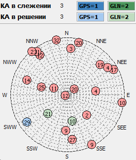
Why do you need Glonass, if GPS works fine? On the right is just such an example. With 23 satellites above the horizon, only 3, 1 GPS and 2 GLONASS are visible in the window. In such conditions, no matter how cool the GPS receiver is, it will not be able to determine the coordinates at all, but for the combined GPS + Glonass receiver there are no fatal problems.
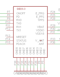 The module has dimensions of 15.9 * 22.1 * 2.5mm, and it turned out to be relatively easy to use: we connect all GND pins to ground, supply 3.3V and 1.8V power to the appropriate outputs (3.3V is the I / O voltage, it can also be 1.8V ), connect the antenna to the ANT input. If the antenna is active (with an amplifier, and requires power), then we also supply 3.3V to the V_ANT input. After that, through RX0 and TX0 (COM-port) you can connect to a microcontroller or computer (in a computer, though, the COM-port gives out +12 and -12V, you need a converter to 3.3V levels, for example, on a MAX3232 chip). All unused pins can simply not be connected anywhere.
')
Briefly, according to the remaining conclusions: V_BAT - for a lithium battery for storing almanac and ephemeris when the device is turned off, in order to speed up the re-acquisition of satellites. 1PPS is the second tag with an accuracy of 30ns (for example, for an NTP server of the exact time, I will still do this), E_PPS / E_FRQ is the input of the time signal, to increase the accuracy and speed of the capture of coordinates in the assisted mode (will work in the release firmware). PD - switching on the mode of reduced energy consumption, when the module sleeps 90% of the time, and 10% is working, will also work in the release firmware.
We connect
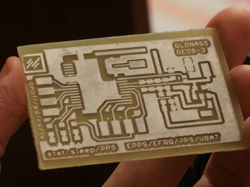 For this module, I made a library symbol in Eagle, and made a simple test board, which also allows me to measure current consumption. You can download my fee and library here . When I made a fee, I forgot that there was a debug connector on the bottom of the module, so I had to stick it with Kapton tape, the symbol in the library already contains a ban on tracing under the debug connector. The wiring should pay attention only to the antenna connection (on the top right of the module) - the earth surrounds the antenna contact on all sides, and is connected to the common ground at one point, so as not to catch unnecessary interference.
Active antenna and SMA connectors were purchased at Dealextreme. Since the frequencies practically coincide with GPS, the antenna works perfectly with both GPS and GLONASS satellites.
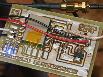 Soldering the module to the board is no more difficult than a microcircuit in a SOIC package: you need a regular soldering iron and a liquid flux (LTI-120 in my case), then we wet everything with a flux, and the surface tension will do all the work. I was reinsured and used low-melting solder ( Sn43 Bi14 ) to make it easier to blow off the module with a hair dryer in case of an error, but this was not necessary.
It worked all at once and did not require any dancing with a tambourine. And of course, you can buy a ready-made debug board (the issue price is ~ $ 400, but I cannot find a link right now).
We use
From a software point of view, working with a module in the simplest case is no different from GPS - the same NMEA protocol (there is also a binary protocol). There is a test program GeoSDemo under windows that allows you to touch everything that is available on the module and update the firmware.
The time of receiving coordinates during cold switching and visibility in the "sky floor" was about 90 seconds (sometimes less, sometimes a little more), usually 10-13 satellites are visible, approximately equally Glonass and GPS. At a voltage of 1.85V (slightly above the norm), the current consumed was 61mA without an energy-saving mode (both when searching for satellites and when there is a capture — the consumption I got is the same).
With the accuracy of determining the coordinates in the test firmware, there are problems - sometimes it is> 10m wrong, I wrote to the manufacturer about it, and I was told to wait for the release, the test firmware for that and test.
The price of the issue is $ 28 in single copies (now apparently there are engineering samples), in bulk - up to $ 15. Such prices, although higher than the Chinese modules on the ancient SiRF Star III, but not so much. There will also be a Geos-3M - the same, only in a more compact package.
So, now we can finally say that GLONASS has become quite affordable even for amateurs.
Ps. Who exactly knows how to calculate the patch antenna on FR4 1.5mm for GPS / Glonass frequencies (1575Mhz + 1602Mhz, only L1 range)? I want to try and integrate the antenna on the board.
Source: https://habr.com/ru/post/138856/
All Articles