Router-on-a-Stick Data Network Architecture
If you are experiencing a shortage of physical ports on the data network equipment, while you are faced with an urgent need to have a second Internet provider or bring some servers to the DMZ using Cisco Systems equipment, then this article should help many novice system administrators to solve this problem. also to those who have recently begun work with data networks and with Cisco equipment in particular. It will be about an architect named Router-on-a-Stick .
Similar to how a switch can divide a local network into multiple VLANs, a router can use a single physical interface to create a subset of logical virtual interfaces and provide routing for data, video, or voice between them.
As a visual example, in the diagrams, I want to demonstrate some possible scenarios that can be implemented using a single physical port and a subset of virtual interfaces on a router or a Cisco firewall.
')
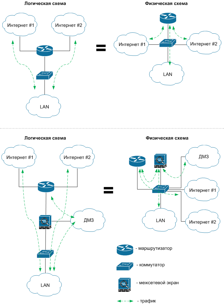
As we can see, a switch is required to solve the task, preferably a 3rd level. The switch must have sufficient bandwidth to reduce potential packet transmission delays in the event of large amounts of traffic. If it is a modular switch, then it is advisable to get a backup power supply and a backup control processor for it.
In addition to the obvious advantages of this architecture, there are also some drawbacks, one of which is the increased load on a single physical port of the device several times. But there are situations when it is impossible to do without virtual interfaces. So, for example, if you digress a little from the topic, it is impossible to build a fault-tolerant bundle of two firewalls in Active / Passive mode, if you don’t connect each of them with a single physical link to the switch, and the second unites them to exchange service data. In case of failure of one firewall, it will take its place second with an identical configuration.
In order not to remain unfounded, I will give an example of the implementation of the simplest model of the architecture Router-on-a-Stick .
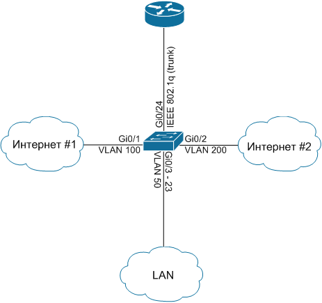
Take a simplified diagram that represents a router connected to a Layer 2 switch. In turn, links from two Internet providers and one company’s internal network with workstations and servers are connected to the switch.
To implement our plans, connect a link from Provider # 1 to Gi0 / 1 port and define it in VLAN 100, and a link from Provider # 2 to Gi0 / 2 port in VLAN 200. Workstations and servers will be located on Gi0 / 3 ports - 23 in VLAN 50. Uplink between the switch and the router will be on port Gi0 / 24, it will be placed in the trunk. The connection diagram is shown in the figure below:
Switch configuration comes down to the following commands:
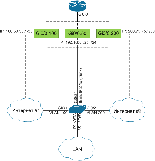
Now that the switch is configured, you need to specify the IP addresses provided by the ISPs and the gateway address for the hosts in VLAN 50. We will indicate them on the router for each VLAN using virtual interfaces. So, we divide one physical interface Gi0 / 0 into three virtual Gi0 / 0.50, Gi0 / 0.100, Gi0 / 0.200 for each VLAN and configure it as shown in the diagram without forgetting about NAT:
To configure the router, apply the following commands:
Finish the configuration by adding two default routes:
Since routes have the same metric, the router will balance the load between them.
I hope that this material will someday be useful to you. Thank!
Similar to how a switch can divide a local network into multiple VLANs, a router can use a single physical interface to create a subset of logical virtual interfaces and provide routing for data, video, or voice between them.
As a visual example, in the diagrams, I want to demonstrate some possible scenarios that can be implemented using a single physical port and a subset of virtual interfaces on a router or a Cisco firewall.
')
As we can see, a switch is required to solve the task, preferably a 3rd level. The switch must have sufficient bandwidth to reduce potential packet transmission delays in the event of large amounts of traffic. If it is a modular switch, then it is advisable to get a backup power supply and a backup control processor for it.
In addition to the obvious advantages of this architecture, there are also some drawbacks, one of which is the increased load on a single physical port of the device several times. But there are situations when it is impossible to do without virtual interfaces. So, for example, if you digress a little from the topic, it is impossible to build a fault-tolerant bundle of two firewalls in Active / Passive mode, if you don’t connect each of them with a single physical link to the switch, and the second unites them to exchange service data. In case of failure of one firewall, it will take its place second with an identical configuration.
In order not to remain unfounded, I will give an example of the implementation of the simplest model of the architecture Router-on-a-Stick .
Take a simplified diagram that represents a router connected to a Layer 2 switch. In turn, links from two Internet providers and one company’s internal network with workstations and servers are connected to the switch.
To implement our plans, connect a link from Provider # 1 to Gi0 / 1 port and define it in VLAN 100, and a link from Provider # 2 to Gi0 / 2 port in VLAN 200. Workstations and servers will be located on Gi0 / 3 ports - 23 in VLAN 50. Uplink between the switch and the router will be on port Gi0 / 24, it will be placed in the trunk. The connection diagram is shown in the figure below:
Switch configuration comes down to the following commands:
telecombook_ru#conf t

telecombook_ru(config)#vlan 50
telecombook_ru(config-vlan)#name DATA
telecombook_ru(config-vlan)#exit

telecombook_ru(config)#vlan 100
telecombook_ru(config-vlan)#name ISP1
telecombook_ru(config-vlan)#exit

telecombook_ru(config)#vlan 200
telecombook_ru(config-vlan)#name ISP2
telecombook_ru(config-vlan)#exit

telecombook_ru(config)#interface Gi0/1
telecombook_ru(config-if)#switchport mode access
telecombook_ru(config-if)#switchport access vlan 100

telecombook_ru(config)#interface Gi0/2
telecombook_ru(config-if)#switchport mode access
telecombook_ru(config-if)#switchport access vlan 200

telecombook_ru(config)#interface range Gi0/3 – 23
telecombook_ru(config-if)#switchport mode access
telecombook_ru(config-if)#switchport access vlan 50

telecombook_ru(config)#interface Gi0/24
telecombook_ru(config-if)#switchport mode trunk
telecombook_ru(config-if)#switchport trunk encapsulation dot1q
Now that the switch is configured, you need to specify the IP addresses provided by the ISPs and the gateway address for the hosts in VLAN 50. We will indicate them on the router for each VLAN using virtual interfaces. So, we divide one physical interface Gi0 / 0 into three virtual Gi0 / 0.50, Gi0 / 0.100, Gi0 / 0.200 for each VLAN and configure it as shown in the diagram without forgetting about NAT:
To configure the router, apply the following commands:
telecombook_ru#conf t
telecombook_ru(config)#interface Gi0/0.50
telecombook_ru(config-if)#encapsulation dot1Q 50
telecombook_ru(config-if)#ip address 192.168.1.254 255.255.255.0
telecombook_ru(config-if)#ip nat inside

telecombook_ru(config)#interface Gi0/0.100
telecombook_ru(config-if)#encapsulation dot1Q 100
telecombook_ru(config-if)#ip address 100.50.50.1 255.255.255.252
telecombook_ru(config-if)#ip nat outside

telecombook_ru(config)#interface Gi0/0.200
telecombook_ru(config-if)#encapsulation dot1Q 200
telecombook_ru(config-if)#ip address 200.75.75.1 255.255.255.252
telecombook_ru(config-if)#ip nat outside

telecombook_ru(config)#ip access-list extended nat-traffic
telecombook_ru(config-acl)#10 permit ip 192.168.1.0 0.0.0.255 any
telecombook_ru(config-acl)#exit

telecombook_ru(config)#route-map isp1 permit 10
telecombook_ru(config-route-map)#match ip address nat-traffic
telecombook_ru(config-route-map)#match interface GigabitEthernet0/0.100
telecombook_ru(config-route-map)#exit

telecombook_ru(config)#route-map isp2 permit 10
telecombook_ru(config-route-map)#match ip address nat-traffic
telecombook_ru(config-route-map)#match interface GigabitEthernet0/0.200
telecombook_ru(config-route-map)#exit

telecombook_ru(config)#ip nat inside source route-map isp1 interface GigabitEthernet0/0.100 overload
telecombook_ru(config)#ip nat inside source route-map isp2 interface GigabitEthernet0/0.200 overload
Finish the configuration by adding two default routes:
telecombook_ru(config)#ip route 0.0.0.0 0.0.0.0 interface Gi0/0.100
telecombook_ru(config)#ip route 0.0.0.0 0.0.0.0 interface Gi0/0.200
Since routes have the same metric, the router will balance the load between them.
I hope that this material will someday be useful to you. Thank!
Source: https://habr.com/ru/post/138573/
All Articles